JP4732954B2 - Mask and manufacturing method thereof - Google Patents
Mask and manufacturing method thereof Download PDFInfo
- Publication number
- JP4732954B2 JP4732954B2 JP2006146688A JP2006146688A JP4732954B2 JP 4732954 B2 JP4732954 B2 JP 4732954B2 JP 2006146688 A JP2006146688 A JP 2006146688A JP 2006146688 A JP2006146688 A JP 2006146688A JP 4732954 B2 JP4732954 B2 JP 4732954B2
- Authority
- JP
- Japan
- Prior art keywords
- cover
- mask
- shaped
- ear
- filter
- Prior art date
- Legal status (The legal status is an assumption and is not a legal conclusion. Google has not performed a legal analysis and makes no representation as to the accuracy of the status listed.)
- Expired - Fee Related
Links
Images


Landscapes
- Respiratory Apparatuses And Protective Means (AREA)
Description
本発明は口および鼻を覆うために用いるマスクおよびその製造方法に関する。 The present invention relates to a mask used for covering the mouth and nose and a method for manufacturing the mask.
従来より、一枚の不織布の端部に耳掛用の切込みを形成した簡易マスクが提案されている。(たとえば、特許文献1)。
前記従来のマスクでは、略長方形の不織布において、中央の本体部分となる箇所の左右の端部に耳掛用の切込みが形成されている。 In the conventional mask, in the non-woven fabric having a substantially rectangular shape, cuts for hooking are formed at the left and right end portions of the central body portion.
しかし、前記従来のマスクは、一枚の不織布により形成されているのでフィット性に乏しく、該従来のマスクを装着すると、顔とマスクとの隙間が大きく空き、マスクとしての機能を十分に発揮することができないおそれがある。 However, since the conventional mask is formed of a single nonwoven fabric, it has poor fit, and when the conventional mask is attached, the gap between the face and the mask is large and fully functions as a mask. There is a risk that it will not be possible.
したがって、本発明の目的は、簡単な構造で密着性の高いマスクおよびその製造方法を提供することである。 Accordingly, an object of the present invention is to provide a mask having a simple structure and high adhesion and a method for manufacturing the same.
前記目的を達成するために、本発明のあるマスクは、口および鼻の開口を覆うことが可能な覆部と、前記覆部の左右に設けられ、耳に係合する耳掛部とが一連の布で連なって形成されたマスクにおいて、前記布における覆部および/または耳掛部の上下の端縁に弾性部材が配置されていることを特徴とする。 In order to achieve the above object, a mask according to the present invention is a series of a cover that can cover the opening of the mouth and nose and ear hooks that are provided on the left and right of the cover and engage the ear. In the mask formed continuously with the cloth, elastic members are arranged on the upper and lower edges of the cover part and / or the ear hook part of the cloth.
本発明によれば、一枚の布を用いた簡単な構造でマスクを製造することができるので、大幅なコストダウンを図り得る。しかも、以下に説明するように、マスクの覆部を着用者の顔に十分に密着させることができる。
本マスクにおいて、覆部の上下の端縁に弾性部材を配置した場合には、該弾性部材の伸縮によって、前記覆部が顔に密着してドーム状の立体形状となるため、マスクの密着性が向上する。
一方、耳掛部の上下の端縁のみに弾性部材を配置した場合においても、覆部の上下の両端部が着用者の耳側に引っ張られることにより、該覆部の顔への密着性を向上させることができる。
さらに、覆部および耳掛部の端縁に渡って連続して弾性部材を配置した場合には、より一層、顔への覆部の密着性が向上する。
According to the present invention, since a mask can be manufactured with a simple structure using a single cloth, a significant cost reduction can be achieved. Moreover, as will be described below, the mask cover can be sufficiently adhered to the wearer's face.
In this mask, when elastic members are arranged at the upper and lower edges of the cover, the cover is brought into close contact with the face by expansion and contraction of the elastic member, so that the mask adheres to the face. Will improve.
On the other hand, even when the elastic members are arranged only at the upper and lower edges of the ear hook, the upper and lower ends of the cover are pulled toward the wearer's ears, thereby improving the adhesion of the cover to the face. Can be improved.
Furthermore, when the elastic member is continuously arranged over the edges of the cover and the ear hook, the adhesion of the cover to the face is further improved.
また、耳掛部の左右の両端には弾性部材が配置されないので、該耳掛部の耳に掛かる部分にギャザ(皺)が形成されないから、マスクの装着時に違和感が生じにくい。
なお、前記“布”としては、たとえば、不織布等を採用することができる。
In addition, since elastic members are not disposed at the left and right ends of the ear hook portion, no gathers are formed in a portion of the ear hook portion that hangs on the ear, so that a sense of incongruity does not easily occur when the mask is worn.
As the “cloth”, for example, a nonwoven fabric or the like can be adopted.
本発明のある製造方法は、通気性を有する連続ウエブを搬送する工程と、前記搬送中の連続ウエブの両側縁に沿って伸張状態の弾性部材を配置する工程と、前記左右の耳掛部を形成するために覆部の両側に切断部を所定の間隔で形成する工程と、隣り合う製品における前記切断部の間において前記連続ウエブを切断して製品ごとに切り分ける工程とを備えている。 A manufacturing method according to the present invention includes a step of conveying a continuous web having air permeability, a step of arranging elastic members in a stretched state along both side edges of the continuous web being conveyed, and the left and right ear hooking portions. In order to form, it has the process of forming a cutting part in the both sides of a cover part with a predetermined space | interval, and the process of cut | disconnecting the said continuous web between the said cutting parts in an adjacent product, and dividing for every product.
この方法によれば、簡易な工程で、密着性の高いマスクを連続的に製造することができる。 According to this method, a mask with high adhesion can be continuously manufactured in a simple process.
本発明の製造方法においては、前記切断部として略コ字状ないし略U字状の切込みが形成され、前記略コ字状ないし略U字状の切込みに囲まれた略方形ないし略U字状の部分が前記覆部に重なるように折り返すことで、耳掛用の孔を形成する折返し工程を更に備えているのが好ましい。
本態様によれば、前記切込みに囲まれた部分が覆部に重なり、二重に重なった布で口および鼻の開口を覆うので、ろ過能力が向上する。
In the manufacturing method of the present invention, a substantially U-shaped or substantially U-shaped cut is formed as the cutting portion, and the substantially rectangular or substantially U-shaped cut surrounded by the substantially U-shaped or substantially U-shaped cut. It is preferable to further include a folding step of forming a hole for the ear hook by folding back so that the portion overlaps the cover.
According to this aspect, the portion surrounded by the cuts overlaps the cover, and the mouth and nose opening are covered with the doubly overlapped cloth, so the filtering ability is improved.
本発明の製造方法においては、前記一対の切込みの間の覆部にフィルタを配置する工程と、前記折り返された折返片と前記覆部との間で前記フィルタを保持することができるように、かつ、耳掛用の孔が形成されるように前記略コ字状ないし略U字状の切込みに囲まれた略方形ないし略U字状の部分が前記覆部に重なるように折り返す工程とを備えているのが好ましい。 In the manufacturing method of the present invention, so as to be able to hold the filter between the step of arranging a filter in the cover between the pair of cuts, and the folded back piece and the cover. And a step of folding back so that a substantially square or substantially U-shaped portion surrounded by the substantially U-shaped or substantially U-shaped cut so as to form an ear hooking hole overlaps the cover. It is preferable to provide.
本態様によれば、折返片と覆部との間にフィルタを保持することにより、二重に重なった布およびフィルタで口および鼻の開口を覆うので、より一層、ろ過能力が向上する。
なお、折返片同士をメカニカルファスナ等を用いて係合自在に設定することにより、フィルタの交換が容易になるので、至便かつ、衛生的である。
前記フィルタは、接着剤や粘着剤、熱融着等を用いて覆部に固定されてもよい。
According to this aspect, by holding the filter between the folded piece and the cover portion, the mouth and the nose opening are covered with the doubly overlapped cloth and filter, so that the filtration performance is further improved.
In addition, since it is easy to replace the filter by setting the folded pieces to be engageable with each other using a mechanical fastener or the like, it is convenient and hygienic.
The filter may be fixed to the cover using an adhesive, a pressure-sensitive adhesive, heat fusion, or the like.
本発明は、添付の図面を参考にした以下の好適な実施例の説明からより明瞭に理解されるであろう。しかしながら、実施例および図面は単なる図示および説明のためのものであり、本発明の範囲を定めるために利用されるべきものではない。本発明の範囲は請求の範囲のみによって定まる。添付図面において、複数の図面における同一の部品番号は、同一または相当部分を示す。 The invention will be more clearly understood from the following description of preferred embodiments with reference to the accompanying drawings, in which: However, the examples and figures are for illustration and description only and should not be used to define the scope of the present invention. The scope of the present invention is defined only by the claims. In the accompanying drawings, the same part numbers in a plurality of drawings indicate the same or corresponding parts.
実施例1:
以下、本発明の実施例が図面にしたがって説明される。
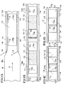
図1Aから図1Dは実施例1を示し、弾性部材を伸張させた状態でマスクを図示している。
Example 1:
Embodiments of the present invention will be described below with reference to the drawings.
FIG. 1A to FIG. 1D show Example 1, and illustrate the mask in a state where the elastic member is stretched.
マスク1:
図1Dはマスク1を、着用者の顔に密着させる面(内面)から見た平面図である。
図1Dに示すように、マスク1は、マスク本体1w、フィルタ13、弾性部材14およびファスナ17を備えている。
Mask 1:
FIG. 1D is a plan view of the
As shown in FIG. 1D, the
マスク本体1w;
前記マスク本体1wは、たとえば、通気性を有する1枚の不織布からなり、着用者の鼻および口の開口を覆う覆部10と、該覆部10の左右に設けられた耳掛部11,11を備えている。前記耳掛部11は、耳の付け根の近傍において耳に係合することが可能であり、たとえば略コ字状や略U字状に形成してもよく、着用者の耳を挿通する耳掛用の孔12が前記覆部10との間に形成されている。
The mask
前記覆部10および耳掛部11,11の上下の端縁1s,1sには、該覆部10および耳掛部11,11を含むマスク1の全長に渡って弾性部材14,14が配設されている。前記弾性部材14は、たとえば、1本ないし複数本の弾性糸や弾性フィルムなどで構成されている。前記弾性部材14,14は、それぞれ、マスク本体1wの端縁1sが折り返されていることによりマスク本体1wに固定されている。
一方、耳掛部11,11の左右の端部11s,11sには、弾性部材14,14が配置されていない。
On the other hand, the
耳掛部11;
図1Cに示すように、覆部10の左右の折返し片15a,15bが覆部10に向って折り返されることより、耳掛用の孔12が形成されて耳掛部11,11が形成される。
Ear
As shown in FIG. 1C, the left and right folded
ファスナ17:
前記左右の折返し片15a,15bのうち、一方の折返し片15bには、ファスナ17が固定されている。ファスナ17は、左右の折返し片15a,15bが折り返された際に、他方の折返し片15aに係合する位置に設けられている。
Fastener 17:
A
前記ファスナ17としては、たとえば、雄面ファスナからなる(多数のフックを有する)ファスナテープを用いることができる。該ファスナ17に形成された複数(多数)のフックが、不織布からなる他方の折返し片15aの表面に係合することにより、左右の折返し片15a,15bが互いに固定される。
As the
覆部10:
かかるファスナ17による係合により、フィルタ13が、覆部10において、マスク本体1wと左右の折返し片15a,15bとの間に保持される。
Cover 10:
By the engagement by the
フィルタ13:
前記フィルタ13としては、たとえば、ガーゼや不織布など、外気中の微細な粉塵や花粉など、ろ過する対象物に応じて種々の素材を採用することができる。
Filter 13:
As said
前記各部の固定は、接着剤や粘着剤を用いることで行われてもよいし、たとえばソニックなどの超音波を用いた熱融着によって行われてもよい。 The fixing of each part may be performed by using an adhesive or a pressure sensitive adhesive, or may be performed by heat fusion using ultrasonic waves such as sonic.
着用者が前記耳掛用の孔12に耳を通して本マスク1を装着すると、覆部10および耳掛部11,11の上下の端縁1s,1sに渡って連続して設けられた弾性部材14,14がそれぞれ伸張される。伸張された弾性部材14の収縮力により、左右の折返し片15a,15b(覆部10)が着用者の顔に沿って密着する。そのため、着用者の顔と覆部10との間に隙間が生じにくくなる。
また、耳掛部11,11の左右の端部11s,11sには、弾性部材14が配置されていないので、該左右の端部11s,11sにギャザが生じないから、着用者の耳に違和感が生じにくい。
When the wearer wears the
Further, since the
さらに、左右の折返し片15a,15bは、ファスナ17を用いて係合しているので、左右の折返し片15a,15bの係合を解いて、折返し片15a,15bを開くことができる。したがって、左右の折返し片15a,15bを開いて、フィルタ13の交換を簡単に行うことができるので、至便、かつ、衛生的である。
Further, since the left and right folded
なお、前記耳掛部11,11の形状は、図1Dに示すコ字状の他に、角が丸みを帯びた略U字状などの形状であってもよい。 In addition, the shape of the ear hooks 11 and 11 may be a substantially U shape with rounded corners in addition to the U shape shown in FIG. 1D.
また、図1Dの斜線で示すマスク本体1wの覆部10の左右の両端部と左右の折返し片15a,15bの基端部とを熱融着などにより互いに固定してもよい。かかる場合には、覆部10の左右の両端部の剛性が大きくなるので、覆部10の左右の両端部の保形性が高まるから、着用者の顔と覆部10との間に隙間が更に生じにくくなる。
Also, the left and right ends of the
さらに、左右の折返し片15a,15bを折り返さずに出荷し、着用者がフィルタ13を配置した後、該左右の折返し片15a,15bを折返し、ファスナ17で該フィルタ13を固定するようにしてもよい。
Further, the left and right folded
また、前記フィルタ13は、覆部10に予め固着されていてもよい。また、ファスナ17を用いず、左右の折返し片15a,15bの端部同士を互いに固着してもよい。
また、必ずしもフィルタ13を用いる必要はない。
さらには、マスク本体1wを2枚の不織布等で構成し、弾性部材14,14を当該2枚の不織布の間に挟み込んで固定するようにしてもよい。
The
Further, it is not always necessary to use the
Furthermore, the
製造方法:
図1Aに示すように、通気性を有する不織布からなる連続ウエブWは、搬送方向Xに沿って張力が付与され、伸張された状態で搬送される。
前記搬送中の連続ウエブWの両側縁Wsには、搬送方向Xに沿って張力が付与されて伸張された状態の弾性部材14が配置される。該配置後に前記両側縁Wsが連続ウエブWの中央部に向って折り返されて固定される。
Production method:
As shown in FIG. 1A, the continuous web W made of a non-woven fabric having air permeability is transported in a stretched state with tension applied along the transport direction X.
一方、前記耳掛部11,11に対応する部分には、該耳掛部11を形成するための略コ字状の一対の切込み(切断部の一例)15,15が所定の間隔で形成される。両切込み15,15の形成により、連続ウエブWに左右の折返し片15a,15bが形成される。切込み15,15は、覆部10となる部分を中心に互いに対象な形状に形成され、覆部10の左右の両側に前記左右の折返し片15a,15bが形成される。
なお、前記切込み15の形状は、略U字状であってもよい。
On the other hand, a pair of substantially U-shaped cuts (an example of a cutting part) 15 and 15 for forming the
The shape of the
その後、図1Bに示すように、一対の切込み15,15の間の覆部10にはフィルタ13が配置されると共に、一方の折返し片15bのたとえば端部にはファスナ17が固定される。これにより積層体100が形成される。
Thereafter, as shown in FIG. 1B, the
その後、図1Cに示すように、まず、ファスナ17が固定されていない側の折返し片15aが覆部10に重なるように折り返される。次にファスナ17の固定された折返し片15bが覆部10に重なるように折り返される。かかる折返しにより、耳掛用の孔12,12が形成されると共に、一方の折返し片15bに設けられたファスナ17が、他方の折返し片15aの表面に係合する。かかる折返しにより、フィルタ13が覆部10においてマスク本体1wと左右の折返し片15a,15bとの間に保持される。
Thereafter, as shown in FIG. 1C, first, the folded
その後、切断線CL(図1B)に沿って連続ウエブWが切断されて、積層体が図1Dに示すマスク1毎に切り分けられる。
Thereafter, the continuous web W is cut along the cutting line CL (FIG. 1B), and the stacked body is cut for each
実施例2:
図2A〜図2Dは実施例2を示す。
図2Dに示すように、本実施例2のマスク1は、覆部10部分に対応する部分の弾性部材14の収縮力が発揮されないように設定されている。
その他の構成は、実施例1と同様であり、同一部分または相当部分に同一符号を付して、その説明を省略する。
Example 2:
2A to 2D show Example 2. FIG.
As shown in FIG. 2D, the
Other configurations are the same as those of the first embodiment, and the same reference numerals are given to the same portions or corresponding portions, and the description thereof is omitted.
実施例2のマスク1を製造するには、図2Aに示すように、連続ウエブWの両側縁Wsに弾性部材14を配置し、該側縁Wsを折り返した後、覆部10に相当する部分の弾性部材14を熱溶断などによって短くカットすることにより、その収縮力を失わせる。この場合、弾性部材14を連続的に配置できるので、弾性部材14の配置工程を容易に実現することができる。
その後の工程は実施例1と同様であり、以後の工程の説明を省略する。
In order to manufacture the
Subsequent steps are the same as those in the first embodiment, and description of the subsequent steps is omitted.
実施例3:
図3A〜図3Dは実施例3を示す。
図3Dに示すように、本実施例3のマスク1では、耳掛部11,11に対応する部分の弾性部材14の収縮力が発揮されないように設定されている。
実施例3のマスク1を製造するには、図3Aに示すように、連続ウエブWの両側縁Wsに弾性部材14を配置し、該側縁Wsを折り返した後、耳掛部11,11に相当する部分の弾性部材14を熱溶断などによって短くカットすることによりその収縮力を失わせる。
なお、前記実施例2,3において弾性部材14の収縮力が発揮されないようにする代わりに、覆部10または耳掛部11,11に弾性部材14を断続的に配置しないようにしてもよい。
Example 3:
3A to 3D show Example 3. FIG.
As shown in FIG. 3D, the
In order to manufacture the
In the second and third embodiments, the
実施例4:
図4A〜図4Cは実施例4を示す。
図4Cに示すように、本実施例4のマスク1には、耳掛用の孔(切断部の一例)12がダイカットされている。すなわち、図4Aおよび図4Bに示すように、連続ウエブWの耳掛用の孔12に相当する部分、つまり、覆部10の左右の両側の部分が打ち抜かれることにより、耳掛用の孔12が形成されている。なお、覆部10にはフィルタ13が固着されている。
その他の構成は、実施例1と同様であり、同一部分または相当部分に同一符号を付して、その説明を省略する。
Example 4:
4A to 4C show Example 4. FIG.
As shown in FIG. 4C, a hook 1 (an example of a cutting part) 12 is die-cut in the
Other configurations are the same as those of the first embodiment, and the same reference numerals are given to the same portions or corresponding portions, and the description thereof is omitted.
なお、前述の実施例4では、図4Cに示すように、耳掛用の孔12を方形に打ち抜く事としたが、耳掛用の孔12の形状としては、たとえば、円形や楕円形であってもよい。
また、耳掛用の孔を打ち抜く代わりに、直線や曲線状に耳掛部内を切込んでもよい。かかる場合には、マスクを装着する際に着用者が、かかる切込みに耳を通してマスクを着用する。
In Example 4 described above, as shown in FIG. 4C, the
Further, instead of punching the hole for the ear hook, the inside of the ear hook portion may be cut in a straight line or a curved line. In such a case, when wearing the mask, the wearer wears the mask through his / her ear through such an incision.
本発明は、たとえば、衛生用や花粉症対策などに用いるマスクに適用することができる。 The present invention can be applied to, for example, a mask used for hygiene and hay fever countermeasures.
1:マスク
10:覆部
11:耳掛部
12:耳掛用の孔(切断部の一例)
13:フィルタ
14:弾性部材
15:切込み(切断部の一例)
W:連続ウエブ
1: Mask 10: Cover 11: Ear hook 12: Hole for ear hook (an example of a cutting part)
13: Filter 14: Elastic member 15: Cutting (an example of a cutting part)
W: Continuous web
Claims (4)
前記布における覆部および/または耳掛部の上下の端縁に、伸縮性を有する弾性部材が配置されていることを特徴とするマスク。 In a mask in which a cover that can cover the opening of the mouth and nose, and ear hooks that are provided on the left and right sides of the cover and that engage with the ears are connected by a series of cloths.
An elastic member having elasticity is disposed on the upper and lower edges of the cover and / or the ear hook on the cloth.
通気性を有する連続ウエブを搬送する工程と、
前記搬送中の連続ウエブの両側縁に沿って伸張状態の弾性部材を配置する工程と、
前記左右の耳掛部を形成するために覆部の両側に切断部を所定の間隔で形成する工程と、
隣り合う製品における前記切断部の間において前記連続ウエブを切断して製品ごとに切り分ける工程とを備えたマスクの製造方法。 A method of manufacturing the mask of claim 1, comprising:
Conveying a continuous web having air permeability;
Arranging an elastic member in an extended state along both side edges of the continuous web being conveyed;
Forming cut portions at predetermined intervals on both sides of the cover portion to form the left and right ear hook portions;
And a step of cutting the continuous web between the cut portions of adjacent products to separate the products into products.
前記略コ字状ないし略U字状の切込みに囲まれた略方形ないし略U字状の部分が前記覆部に重なるように折り返すことで、耳掛用の孔を形成する折返し工程を更に備えたマスクの製造方法。 In claim 2, a substantially U-shaped or substantially U-shaped cut is formed as the cutting portion,
The method further includes a folding step of forming a hole for an ear hook by folding the substantially square or substantially U-shaped portion surrounded by the substantially U-shaped or substantially U-shaped cut so as to overlap the cover portion. Mask manufacturing method.
前記折り返された折返片と前記覆部との間で前記フィルタを保持することができるように、かつ、耳掛用の孔が形成されるように前記略コ字状ないし略U字状の切込みに囲まれた略方形ないし略U字状の部分が前記覆部に重なるように折り返す工程とを備えたマスクの製造方法。 In claim 3, the step of arranging a filter in the cover between the pair of cuts;
The substantially U-shaped or substantially U-shaped notch so that the filter can be held between the folded-back folded piece and the cover and an ear hooking hole is formed. And a step of folding back so that a substantially square or substantially U-shaped portion surrounded by the upper surface overlaps the cover.
Priority Applications (1)
| Application Number | Priority Date | Filing Date | Title |
|---|---|---|---|
| JP2006146688A JP4732954B2 (en) | 2006-05-26 | 2006-05-26 | Mask and manufacturing method thereof |
Applications Claiming Priority (1)
| Application Number | Priority Date | Filing Date | Title |
|---|---|---|---|
| JP2006146688A JP4732954B2 (en) | 2006-05-26 | 2006-05-26 | Mask and manufacturing method thereof |
Publications (2)
| Publication Number | Publication Date |
|---|---|
| JP2007313085A JP2007313085A (en) | 2007-12-06 |
| JP4732954B2 true JP4732954B2 (en) | 2011-07-27 |
Family
ID=38847494
Family Applications (1)
| Application Number | Title | Priority Date | Filing Date |
|---|---|---|---|
| JP2006146688A Expired - Fee Related JP4732954B2 (en) | 2006-05-26 | 2006-05-26 | Mask and manufacturing method thereof |
Country Status (1)
| Country | Link |
|---|---|
| JP (1) | JP4732954B2 (en) |
Families Citing this family (4)
| Publication number | Priority date | Publication date | Assignee | Title |
|---|---|---|---|---|
| JP5076158B2 (en) * | 2008-12-25 | 2012-11-21 | 株式会社瑞光 | Disposable mask and manufacturing method thereof |
| JP5292583B2 (en) * | 2009-02-18 | 2013-09-18 | 株式会社瑞光 | Disposable mask and manufacturing method thereof |
| TWI406685B (en) * | 2009-09-07 | 2013-09-01 | Kang Na Hsiung Entpr Co Ltd | Printed mask manufacturing method |
| US20230354930A1 (en) * | 2020-04-03 | 2023-11-09 | Zuiko Corporation | Mask and method for producing same |
Family Cites Families (5)
| Publication number | Priority date | Publication date | Assignee | Title |
|---|---|---|---|---|
| US4361781A (en) * | 1980-05-12 | 1982-11-30 | International Business Machines Corporation | Multiple electron beam cathode ray tube |
| JPS5930429B2 (en) * | 1980-08-25 | 1984-07-26 | 三晶株式会社 | How to make a simple mask |
| DE3776363D1 (en) * | 1986-02-19 | 1992-03-12 | Eastman Kodak Co | ANIMAL FEED SUPPLEMENTATION FORMULATION. |
| JPH0394261A (en) * | 1989-09-06 | 1991-04-19 | Konica Corp | Electrophotographic sensitive body |
| JPH0783769B2 (en) * | 1990-03-02 | 1995-09-13 | 株式会社岸製作所 | Disposable mask manufacturing equipment |
-
2006
- 2006-05-26 JP JP2006146688A patent/JP4732954B2/en not_active Expired - Fee Related
Also Published As
| Publication number | Publication date |
|---|---|
| JP2007313085A (en) | 2007-12-06 |
Similar Documents
| Publication | Publication Date | Title |
|---|---|---|
| JP4794264B2 (en) | mask | |
| CN103561821B (en) | The manufacture method of mask, mask | |
| CN103635233B (en) | Mouth mask | |
| JP3824461B2 (en) | Disposable mask and manufacturing method thereof | |
| CN103533989B (en) | Mouth mask | |
| KR101918084B1 (en) | The multi-folding type dust mask to get secure air chamber | |
| JP5292583B2 (en) | Disposable mask and manufacturing method thereof | |
| KR102085233B1 (en) | Mask and method for manufacturing the same | |
| JP6097241B2 (en) | mask | |
| WO2012137942A1 (en) | Mask | |
| US20050059950A1 (en) | Absorbent garments with extendable side panels | |
| JP2007021029A (en) | mask | |
| JP2011239871A (en) | Four-face mask | |
| JP7433742B2 (en) | hygiene mask | |
| JP3162028U (en) | Side-fit mask | |
| JP7383129B2 (en) | Mask and mask manufacturing method | |
| JP4732954B2 (en) | Mask and manufacturing method thereof | |
| WO2022044597A1 (en) | Mask | |
| JP3229358U (en) | Mask seal and mask seal set | |
| JP5076158B2 (en) | Disposable mask and manufacturing method thereof | |
| JP2005328937A (en) | Three-dimensional mask | |
| TW202200236A (en) | Face mask | |
| JP2020111871A (en) | mask | |
| EP4316605B1 (en) | Mask and method for manufacturing mask | |
| WO2013002225A1 (en) | Mask |
Legal Events
| Date | Code | Title | Description |
|---|---|---|---|
| A621 | Written request for application examination |
Free format text: JAPANESE INTERMEDIATE CODE: A621 Effective date: 20090508 |
|
| A977 | Report on retrieval |
Free format text: JAPANESE INTERMEDIATE CODE: A971007 Effective date: 20110208 |
|
| A131 | Notification of reasons for refusal |
Free format text: JAPANESE INTERMEDIATE CODE: A131 Effective date: 20110215 |
|
| A521 | Request for written amendment filed |
Free format text: JAPANESE INTERMEDIATE CODE: A523 Effective date: 20110330 |
|
| TRDD | Decision of grant or rejection written | ||
| A01 | Written decision to grant a patent or to grant a registration (utility model) |
Free format text: JAPANESE INTERMEDIATE CODE: A01 Effective date: 20110419 |
|
| A01 | Written decision to grant a patent or to grant a registration (utility model) |
Free format text: JAPANESE INTERMEDIATE CODE: A01 |
|
| A61 | First payment of annual fees (during grant procedure) |
Free format text: JAPANESE INTERMEDIATE CODE: A61 Effective date: 20110421 |
|
| FPAY | Renewal fee payment (event date is renewal date of database) |
Free format text: PAYMENT UNTIL: 20140428 Year of fee payment: 3 |
|
| R150 | Certificate of patent or registration of utility model |
Ref document number: 4732954 Country of ref document: JP Free format text: JAPANESE INTERMEDIATE CODE: R150 Free format text: JAPANESE INTERMEDIATE CODE: R150 |
|
| R250 | Receipt of annual fees |
Free format text: JAPANESE INTERMEDIATE CODE: R250 |
|
| R250 | Receipt of annual fees |
Free format text: JAPANESE INTERMEDIATE CODE: R250 |
|
| R250 | Receipt of annual fees |
Free format text: JAPANESE INTERMEDIATE CODE: R250 |
|
| R250 | Receipt of annual fees |
Free format text: JAPANESE INTERMEDIATE CODE: R250 |
|
| R250 | Receipt of annual fees |
Free format text: JAPANESE INTERMEDIATE CODE: R250 |
|
| R250 | Receipt of annual fees |
Free format text: JAPANESE INTERMEDIATE CODE: R250 |
|
| R250 | Receipt of annual fees |
Free format text: JAPANESE INTERMEDIATE CODE: R250 |
|
| R250 | Receipt of annual fees |
Free format text: JAPANESE INTERMEDIATE CODE: R250 |
|
| LAPS | Cancellation because of no payment of annual fees |