JP4768112B2 - Dispenser maintenance equipment - Google Patents
Dispenser maintenance equipment Download PDFInfo
- Publication number
- JP4768112B2 JP4768112B2 JP2000312007A JP2000312007A JP4768112B2 JP 4768112 B2 JP4768112 B2 JP 4768112B2 JP 2000312007 A JP2000312007 A JP 2000312007A JP 2000312007 A JP2000312007 A JP 2000312007A JP 4768112 B2 JP4768112 B2 JP 4768112B2
- Authority
- JP
- Japan
- Prior art keywords
- boom
- contact
- wire rope
- pile
- dispenser
- Prior art date
- Legal status (The legal status is an assumption and is not a legal conclusion. Google has not performed a legal analysis and makes no representation as to the accuracy of the status listed.)
- Expired - Fee Related
Links
- 238000012423 maintenance Methods 0.000 title claims description 17
- 230000002265 prevention Effects 0.000 description 9
- 239000000463 material Substances 0.000 description 3
- 239000003245 coal Substances 0.000 description 2
- 230000000694 effects Effects 0.000 description 2
- 230000007257 malfunction Effects 0.000 description 2
- 238000000034 method Methods 0.000 description 2
- 238000009412 basement excavation Methods 0.000 description 1
- 239000013590 bulk material Substances 0.000 description 1
- 230000008602 contraction Effects 0.000 description 1
- 230000003111 delayed effect Effects 0.000 description 1
- 238000006073 displacement reaction Methods 0.000 description 1
- 230000000087 stabilizing effect Effects 0.000 description 1
- 230000032258 transport Effects 0.000 description 1
Images


Landscapes
- Control Of Conveyors (AREA)
Description
【0001】
【発明の属する技術分野】
本発明は、貯場に積み付けた石炭、鉱石などのばら物を搬出する際に用いられる払出機(リクレーマ)やスタッカ・リクレーマに付設される保全設備に関するものである。
【0002】
【従来の技術】
従来、例えば図5に示すように、船、貨車、コンベヤなどにより搬入された石炭や鉱石などのばら物50をスタッカ(図示省略)により貯場51に積山52にして積み付けて貯蔵し、これを払出機53やスタッカ・リクレーマにより連続的に搬出することが行われている。
【0003】
この周知の払出機53は、図示する前後方向に走行可能な基台54に旋回可能に突出させたブーム55の先端にバケットホィールからなる掻き取り機56が設けられ、ブーム55を走行、旋回、起伏させて掻き取り機56により積み付けられたばら物50を例えばベンチカット方式で積山52上段より順次掻き取り、ブーム55内に配設されたブームコンベヤ57により基台54に配置されたホッパ58へ搬送し、更にその下方に配設されたベルトコンベヤ59に搬出する。
【0004】
このような払出機53のブーム55には、積山52とベルトコンベヤフレーム55aとの接触を事前に検出して接触による機械の損傷を事前に防止する保全設備が付設されている。図6は、払出機53のブーム55に付設された従来の保全設備を示している。この設備は、ブーム55の下方に取り付けたワイヤーロープ60の取付けフレーム63、63によってブーム55の両外側下方に沿ってブーム55の前後方向平行に張設されたワイヤーロープ60、60と、ワイヤーロープ60、60の接触を検出して作動するリミットスイッチ61、61とからなるワイヤーロープ式接触防止装置Sとなっている。これにより、移動中のブーム55のベルトコンベヤフレーム55aが積山52に接触しそうになると、ワイヤーロープ60が事前に積山52に接触することによりリミットスイッチ61がはたらいてブーム55の作動を停止し、ブーム55の損傷を防止するようになっている。
【0005】
【発明が解決しようとする課題】
しかしながら、上記のワイヤーロープ式接触防止装置Sによる保全設備では、ブーム55の下降時の下方接触やブーム55が水平乃至俯角にある旋回時の側方接触にはワイヤーロープ60が事前に接触を確実に検出してリミットスイッチ61を有効に作動させるが、図7に模試的に示すように、ブーム55を仰角にして行う積山上段払出しの場合においては、積山上段52aを一定距離L払い出したとき、ワイヤーロープ60が接触を検出できずにリミットスイッチ61の作動が遅れて、ベルトコンベヤフレーム55aの下面が積山下段52bの上端縁62と接触してしまうことがある。
【0006】
当然、ブーム55の積山上段52aへの前進距離Lは予め設定してあるが、払出機53の誤作動、誤操作、や故障等でブーム55が前進距離Lをオーバーして前進するとき、ワイヤーロープ式接触防止装置Sでは、積山上段払出し時における最も接触し易いベルトコンベヤフレーム55aの位置にワイヤーロープの取付けフレーム63が位置する構成から積山上段払出し時の前進移動に接触ワイヤーロープ60による接触検出が不確実となるものである。
【0007】
本発明は、上記の問題に鑑みてなされたもので、ブームが所定の払出前進距離をオーバーしたとき、積山とブームのベルトコンベヤフレームとの接触検出を確実にして接触事故を防止することにある。
【0008】
【課題を解決するための手段】
本発明は、基台から突出させたブームの先端に掻き取り機が設けられ、前記掻き取り機により積山から掻き取ったばら物を前記ブーム内に配設されたブームベルトコンベヤにより前記基台に配置したホッパへ搬送する払出機に付設される保全設備において、前記ブームの両外側下方に前記積山とブームとの接触を事前に検出するために前記ブームに沿って張設されたワイヤーロープの接触を検出して前記ブームの移動を緊急停止するリミットスイッチを設けるとともに、前記ワイヤーロープよりも前方部の前記ブームの両外側下方に前記積山との接触を検出して前記ブームの移動を緊急停止する一対のチルトスイッチを吊設した。
【0009】
これにより、予め設定してあるブームの積山上段への前進距離をブームがオーバーして前進移動すると、チルトスイッチが下段積山の上端縁近傍と接触して作動し、ブームが積山に接触する前に確実にブームの移動を緊急停止させる。
【0010】
【発明の実施の形態】
以下、本発明の払出機の保全設備の好適な実施の形態を添付図面を参照しながら詳細に説明する。
【0011】
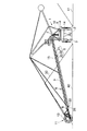
図1は、本発明の払出機の保全設備が装着される払出機の概容を示すもので、払出機1の全体構成は前記従来例とほぼ同様であり、互いに対向して形成された二つの貯場40、41の間に、中央に搬送用ベルトコンベヤ2を配置した軌条3が図示する前後方向に延設されており、この軌条3に基台4が走行可能に配置されている。
【0012】
前記基台4上には旋回装置5を介して長尺のブーム6がその基端7において上下方向回動可能に取り付けられている。このブーム6は内部に先端8から基端7に亘ってブームベルトコンベヤ9が収装されているとともに、基台4のシリンダー10の伸縮により基端7を中心にして起伏可能である。
【0013】
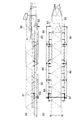
また、ブーム6の先端には、図2に示すように、補助コンベヤ12を備えたバケットホイール13を有する掻き取り機11が設けられており、積山30からバケットホイール13で掻き取ったばら物は補助コンベヤ12を介してブームベルトコンベヤ9によって基台4に設置したホッパ14へ搬送され、更にその下方に配置された搬送用ベルトコンベヤ2へ搬出される。
【0014】
また、ブーム6には、既述した従来例と同様に、積山30と移動するブーム6との接触を事前に検出するためにブーム6の両側下方においてブーム6に沿ってブーム6前方部から後方部に平行して張設されたワイヤーロープ20、20とワイヤーロープ20の積山への接触を検出して作動するリミットスイッチ21とからなるワイヤーロープ式接触防止装置Sが設けられている。
【0015】
このワイヤーロープ式接触防止装置Sにおけるワイヤーロープ20、20は、ベルトコンベヤフレーム15の下方に前後に距離をとってベルトコンベヤフレーム15の両側方から両端部を突出して固定されているワイヤーロープの取付けフレーム22、22の両先端に張設されていることから、水平又は俯角にあるブーム6の旋回時における旋回方向にある積山30との接触をブームの長さ方向へ広い範囲で検出できるとともに、ブーム6の下降時におけるブーム6の下方の積山30との接触を確実に検出する。従って、リミットスイッチ21が作動してブーム6の移動を停止させ、ブーム6の接触事故を事前に防止する。
【0016】
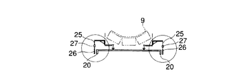
また、ブーム6には、ブームコンベヤフレーム15の両外側下方にあって前記ワイヤーロープ20よりも前方部に、図3、図4に示すように、積山30との接触を検出して作動する一対の棒状のチルトスイッチ26、26が吊設されている。このセンサーを内蔵したチルトスイッチ26は、安定用の重錘27が取り付けられたワイヤーロープ25の下端に吊されており、接触信号を送るケーブル28はコントロールボックス(図示省略)に接続されていおり、所定の角度傾斜することで接触を検出する。
【0017】
図3に示すように、この二つのチルトスイッチ26、26の間隔は平行するワイヤーロープ20、20の間隔よりも広く設定され、且つチルトスイッチ26、26の先端はワイヤーロープ25、25の位置と同位に設定されている。このチルトスイッチ26、26を結ぶ二点間に直交するブームコンベヤフレーム15の下面の位置は、積山上段31払出しのとき、積山下段32の上端縁33が最も接触し易い位置であり、積山上段31払出し時にはチルトスイッチ26、26がワイヤーロープ20、20よりも早く接触を検出する。
【0018】
本実施の形態の払出機の保全設備は以上説明したように構成されており、払出機1が積山30からばら物を払い出すときは、ブーム6を走行、旋回、起伏させて掻き取り機11により例えばベンチカット方式では積山上段31より順次掻き出し、バケットホイール13により掻き取ったばら物を補助コンベヤ12からブームベルトコンベヤ9を経て払い出して行く。
【0019】
積山上段31を払出すときは、ブーム6を仰角にして旋回前進させる。積山上段31を予め設定した前進距離L払い出して行くとき、二つのチルトスイッチを結ぶ二点間と直交するベルトコンベヤフレーム15の下面近傍が積山下段32の上端縁62と最も接近する。
【0020】
積山上段31の払出中に、払出機1の誤作動、誤操作や故障等、何らかの原因でブーム6が前進距離Lをオーバーして前進すると、チルトスイッチ26が積山下段32の上端縁62近傍に接触する。
【0021】
積山30との接触によるチルトスイッチ26の変位により直ちチルトスイッチ26が作動してブーム6が緊急停止し、ブーム6の接触事故が回避される。
【0022】
積山下段32の払出しでは、ブーム6は水平又は俯角で旋回するので、ホイル掘削面よりもチルトスイッチ26の位置が高く接触しないため、旋回方向にある積山30とブーム6の長さ方向広い範囲の側方接触は発生しない。尚、ブーム6の下降時の下方接触はワイヤーロープ式接触防止装置Sで検出する。
【0023】
上記のチルトスイッチ26とワイヤーロープ式接触防止装置Sとによる払出機の保全設備は、リクレーマだけではなくスタッカ・リクレーマにも用いられることは言うまでもない。
【0024】
【発明の効果】
本発明は、以上説明したような形態で実施され、以下に記載されるような効果を奏する。
【0025】
ワイヤーロープ式接触防止装置よりも前方部のブームの両外側下方に積山との接触を検出してブームの移動を緊急停止する一対のチルトスイッチを吊設したので、ブームが予め設定してあるブームの積山上段への前進距離をオーバーすると、事前にチルトスイッチが下段積山との接触を確実に検出する。従って、ブームが積山に接触する前に確実にブームの移動を緊急停止させて機械の安全を計ることができる。
【0026】
また、チルトスイッチとワイヤーロープ式接触防止装置とからなるブームに配設された保全設備は、接触を機械的に検出する手段であるので、ソフト的な制御手段の故障のバックアップとして使用することが可能であり、払出機のフェールセーフ機能としても有用である。
【図面の簡単な説明】
【図1】本発明の払出機の保全保全設備の実施の形態を示す払出機の側面概略図。
【図2】図1の実施の形態における主要部を拡大して示す側面図。
【図3】図2のA矢視方向を示す説明図。
【図4】図3の説明図におけるチルトスイッチの拡大正面図。
【図5】従来の払出機の保全設備を示す払出機の側面概略図。
【図6】図5の払出機に用いられた保全設備の(a)は側面図、(b)は平面図。
【図7】図5の払出機の保全設備の使用状態を説明する拡大側面概略図。
【符号の説明】
1 払出機,4 基台,6 ブーム,9 ブームベルトコンベヤ,11 掻き取り機,14 ホッパ,20 ワイヤーロープ,21 リミットスイッチ,26チルトスイッチ,30 積山,[0001]
BACKGROUND OF THE INVENTION
The present invention relates to a maintenance machine attached to a dispenser (reclaimer) or a stacker / reclaimer used when carrying out bulk materials such as coal and ore loaded in a storage.
[0002]
[Prior art]
Conventionally, as shown in FIG. 5, for example, bulks 50 such as coal and ore carried by a ship, a freight car, a conveyor, etc. are stacked and stored in a
[0003]
This known
[0004]
The
[0005]
[Problems to be solved by the invention]
However, in the maintenance facility using the wire rope contact prevention device S described above, the
[0006]
Naturally, the advance distance L of the
[0007]
The present invention has been made in view of the above problem, and is to prevent contact accidents by reliably detecting contact between a pile and a belt conveyor frame of a boom when a boom exceeds a predetermined payout advance distance. .
[0008]
[Means for Solving the Problems]
According to the present invention, a scraper is provided at the tip of a boom projecting from a base, and loose materials scraped from the pile by the scraper are attached to the base by a boom belt conveyor disposed in the boom. In a maintenance facility attached to a dispenser that transports to a disposed hopper, contact of a wire rope stretched along the boom in order to detect in advance contact between the pile and the boom on both lower sides of the boom A limit switch for emergency stop of the movement of the boom is detected, and contact with the mountain is detected below both the outer sides of the boom in front of the wire rope to stop the movement of the boom urgently. A pair of tilt switches was suspended.
[0009]
As a result, when the boom moves forward with the preset advance distance of the boom to the upper pile, the tilt switch operates in contact with the vicinity of the upper edge of the lower pile and before the boom contacts the pile. Make sure to stop the boom movement in an emergency.
[0010]
DETAILED DESCRIPTION OF THE INVENTION
DESCRIPTION OF EXEMPLARY EMBODIMENTS Hereinafter, preferred embodiments of a maintenance facility for a dispensing machine according to the invention will be described in detail with reference to the accompanying drawings.
[0011]
FIG. 1 shows an outline of a dispenser to which a maintenance facility for a dispenser according to the present invention is attached. The overall configuration of the dispenser 1 is substantially the same as that of the conventional example, and two of the dispensers formed to face each other. Between the
[0012]
A
[0013]
Moreover, as shown in FIG. 2, the
[0014]
Similarly to the conventional example described above, the
[0015]
The wire ropes 20 and 20 in the wire rope type contact prevention device S are attached to a wire rope that is fixed by projecting both ends from both sides of the
[0016]
Further, the
[0017]
As shown in FIG. 3, the distance between the two
[0018]
The maintenance equipment of the dispenser according to the present embodiment is configured as described above. When the dispenser 1 dispenses loose materials from the
[0019]
When paying out the
[0020]
When the
[0021]
The
[0022]
Since the
[0023]
It goes without saying that the maintenance equipment of the dispenser by the
[0024]
【The invention's effect】
The present invention is implemented in the form as described above, and has the following effects.
[0025]
The boom is set in advance because the pair of tilt switches that suspend the movement of the boom urgently by detecting contact with the piles below both the outer sides of the boom at the front part of the wire rope type contact prevention device. When the advance distance to the upper stage of the mountain is exceeded, the tilt switch reliably detects contact with the lower mountain in advance. Therefore, before the boom contacts the mountain, the movement of the boom can be stopped urgently and the safety of the machine can be measured.
[0026]
In addition, since the maintenance equipment arranged on the boom composed of the tilt switch and the wire rope type contact prevention device is a means for mechanically detecting contact, it can be used as a backup for failure of the software control means. It is possible and useful as a fail-safe function of the dispenser.
[Brief description of the drawings]
FIG. 1 is a schematic side view of a dispenser showing an embodiment of a maintenance facility for the dispenser of the present invention.
FIG. 2 is an enlarged side view showing a main part in the embodiment of FIG.
FIG. 3 is an explanatory view showing the direction of arrow A in FIG. 2;
4 is an enlarged front view of the tilt switch in the explanatory view of FIG. 3;
FIG. 5 is a schematic side view of a dispenser showing maintenance equipment for a conventional dispenser.
6A is a side view and FIG. 6B is a plan view of maintenance equipment used in the dispensing machine of FIG. 5;
FIG. 7 is an enlarged schematic side view illustrating the usage state of the maintenance equipment of the dispensing machine in FIG. 5;
[Explanation of symbols]
1 Dispenser, 4 base, 6 boom, 9 boom belt conveyor, 11 scraper, 14 hopper, 20 wire rope, 21 limit switch, 26 tilt switch, 30 mountain,
Claims (1)
Priority Applications (1)
| Application Number | Priority Date | Filing Date | Title |
|---|---|---|---|
| JP2000312007A JP4768112B2 (en) | 2000-10-12 | 2000-10-12 | Dispenser maintenance equipment |
Applications Claiming Priority (1)
| Application Number | Priority Date | Filing Date | Title |
|---|---|---|---|
| JP2000312007A JP4768112B2 (en) | 2000-10-12 | 2000-10-12 | Dispenser maintenance equipment |
Publications (2)
| Publication Number | Publication Date |
|---|---|
| JP2002114379A JP2002114379A (en) | 2002-04-16 |
| JP4768112B2 true JP4768112B2 (en) | 2011-09-07 |
Family
ID=18791675
Family Applications (1)
| Application Number | Title | Priority Date | Filing Date |
|---|---|---|---|
| JP2000312007A Expired - Fee Related JP4768112B2 (en) | 2000-10-12 | 2000-10-12 | Dispenser maintenance equipment |
Country Status (1)
| Country | Link |
|---|---|
| JP (1) | JP4768112B2 (en) |
Cited By (2)
| Publication number | Priority date | Publication date | Assignee | Title |
|---|---|---|---|---|
| CN102502206A (en) * | 2011-10-25 | 2012-06-20 | 三一重型装备有限公司 | Diagonal tensile cantilever type conveyor |
| CN102765606A (en) * | 2012-07-30 | 2012-11-07 | 大连华锐重工集团股份有限公司 | Two tripper cars of electric variable-amplitude type wheel-bucket stack-taking machine |
Families Citing this family (4)
| Publication number | Priority date | Publication date | Assignee | Title |
|---|---|---|---|---|
| CN101823631B (en) * | 2010-04-22 | 2012-03-07 | 青岛港(集团)有限公司 | Protective device of elevating mechanism of stacker-reclaimer |
| JP6810594B2 (en) * | 2016-12-15 | 2021-01-06 | Ihi運搬機械株式会社 | Collision prevention device |
| CN110104444B (en) * | 2019-05-27 | 2024-04-16 | 佛山市恒途机械有限公司 | Timber stacking device and timber stacker |
| CN116534559B (en) * | 2023-05-17 | 2024-02-23 | 中国铝业股份有限公司 | A belt conveyor for bauxite mining |
Family Cites Families (6)
| Publication number | Priority date | Publication date | Assignee | Title |
|---|---|---|---|---|
| JPS58170318U (en) * | 1982-05-10 | 1983-11-14 | 住友重機械工業株式会社 | Collision prevention device for movable boom |
| JPS5938617A (en) * | 1982-08-27 | 1984-03-02 | Hitachi Ltd | Supporting device for stack detector |
| JPS60110330U (en) * | 1983-12-27 | 1985-07-26 | 川崎製鉄株式会社 | Reclaimer beam contact prevention device |
| JPH0620763Y2 (en) * | 1987-04-13 | 1994-06-01 | 石川島播磨重工業株式会社 | Hatch collision prevention device for cargo handling machine |
| JP3420285B2 (en) * | 1993-06-16 | 2003-06-23 | 株式会社三井三池製作所 | Loading / unloading device |
| JPH11147616A (en) * | 1997-11-17 | 1999-06-02 | Mitsui Miike Mach Co Ltd | Storage tank bulk storage device |
-
2000
- 2000-10-12 JP JP2000312007A patent/JP4768112B2/en not_active Expired - Fee Related
Cited By (3)
| Publication number | Priority date | Publication date | Assignee | Title |
|---|---|---|---|---|
| CN102502206A (en) * | 2011-10-25 | 2012-06-20 | 三一重型装备有限公司 | Diagonal tensile cantilever type conveyor |
| CN102502206B (en) * | 2011-10-25 | 2014-07-02 | 三一重型装备有限公司 | Diagonal tensile cantilever type conveyor |
| CN102765606A (en) * | 2012-07-30 | 2012-11-07 | 大连华锐重工集团股份有限公司 | Two tripper cars of electric variable-amplitude type wheel-bucket stack-taking machine |
Also Published As
| Publication number | Publication date |
|---|---|
| JP2002114379A (en) | 2002-04-16 |
Similar Documents
| Publication | Publication Date | Title |
|---|---|---|
| US3836021A (en) | Apparatus for handling mail bags | |
| KR101498399B1 (en) | Tripper connecting/separating device of stacker/reclaimer and method thereof | |
| JP4768112B2 (en) | Dispenser maintenance equipment | |
| RU2125535C1 (en) | Loose load grading device | |
| KR101344315B1 (en) | Emergency breaking device for continuous ship unloader | |
| US5157801A (en) | Dock leveler having automatically actuated vehicle barrier | |
| KR20130000762A (en) | Apparatus for preventing collision of unloader | |
| JP3386720B2 (en) | Combine grain unloading device | |
| KR102846015B1 (en) | Protection apparatus for running wheel of continuous ship unloader | |
| KR101928172B1 (en) | Anti-collision type continuous ship unloader | |
| KR100368249B1 (en) | Prevention of Blanking of Raw Material Dispenser_ | |
| JP2001187641A (en) | Ship unloading device | |
| KR200284328Y1 (en) | Collision Avoidance Device for Stacker Bucket | |
| JP2008070123A (en) | Vehicle tilt angle measuring machine | |
| JPH075116B2 (en) | Ship tank unloading device | |
| KR102588140B1 (en) | Continuous ship unloader | |
| JPH09315588A (en) | Continuous unloader | |
| JPS642004B2 (en) | ||
| US11987473B2 (en) | Escalator device | |
| JP2000211577A (en) | Ship unloading device | |
| US4603778A (en) | Detection of defects in conveyor belts | |
| JP2502146Y2 (en) | Fall prevention device for cargo handling machine equipped with undulating boom | |
| JPH11171349A (en) | Evacuation method and evacuation control device when ship oscillates in continuous unloader automatic operation | |
| JP3758946B2 (en) | A self-propelled vehicle equipped with a transfer device | |
| KR100910475B1 (en) | Ore Treatment Unit of Discharge Equipment Auxiliary Chute |
Legal Events
| Date | Code | Title | Description |
|---|---|---|---|
| A621 | Written request for application examination |
Free format text: JAPANESE INTERMEDIATE CODE: A621 Effective date: 20071012 |
|
| A131 | Notification of reasons for refusal |
Free format text: JAPANESE INTERMEDIATE CODE: A131 Effective date: 20110118 |
|
| A521 | Written amendment |
Free format text: JAPANESE INTERMEDIATE CODE: A523 Effective date: 20110318 |
|
| A01 | Written decision to grant a patent or to grant a registration (utility model) |
Free format text: JAPANESE INTERMEDIATE CODE: A01 Effective date: 20110517 |
|
| A61 | First payment of annual fees (during grant procedure) |
Free format text: JAPANESE INTERMEDIATE CODE: A61 Effective date: 20110616 |
|
| R150 | Certificate of patent or registration of utility model |
Free format text: JAPANESE INTERMEDIATE CODE: R150 |
|
| FPAY | Renewal fee payment (event date is renewal date of database) |
Free format text: PAYMENT UNTIL: 20140624 Year of fee payment: 3 |
|
| R250 | Receipt of annual fees |
Free format text: JAPANESE INTERMEDIATE CODE: R250 |
|
| LAPS | Cancellation because of no payment of annual fees |