JP4787623B2 - High altitude saw - Google Patents
High altitude saw Download PDFInfo
- Publication number
- JP4787623B2 JP4787623B2 JP2006029070A JP2006029070A JP4787623B2 JP 4787623 B2 JP4787623 B2 JP 4787623B2 JP 2006029070 A JP2006029070 A JP 2006029070A JP 2006029070 A JP2006029070 A JP 2006029070A JP 4787623 B2 JP4787623 B2 JP 4787623B2
- Authority
- JP
- Japan
- Prior art keywords
- saw
- saw blade
- support
- piston
- support bar
- Prior art date
- Legal status (The legal status is an assumption and is not a legal conclusion. Google has not performed a legal analysis and makes no representation as to the accuracy of the status listed.)
- Expired - Fee Related
Links
Images


Landscapes
- Sawing (AREA)
Description
本発明は、高所にある樹木の枝や、高所にある建造物の一部分を切断するのに適した鋸に関する。 The present invention relates to a saw suitable for cutting a branch of a tree in a high place or a part of a building in a high place.
高所にある樹木の枝を切断する鋸としては、長い柄の先端に鋸刃を取り付けたもの(特許文献1〜3)、チェーンソー等を取り付けたもの(特許文献4、5)などが考案されている。しかし、前者は長い柄の部分を手で持って押したり引いたりするものであるため、例えば人の背丈の2倍を超えるような高所の枝を切る場合、切りたい位置に鋸刃を正確に当てること、および切断中その位置がずれないように鋸刃に力を加えることは必ずしも容易でない。また、柄が長くなると鋸の重量が増大し、肉体的な負担が過大となって作業効率は低下する。後者は刃部に付随するモーター等の動力源を一緒に持ち上げる必要があり、これは本来重いものであるから、柄を長くすることには限界がある。したがって、これら柄を直接手で持ち上げるタイプの鋸(以下「手持ち鋸」という)でかなり高所の枝を切るには、結局、切りたい枝のできるだけ近くまで梯子や脚立などで登って作業する必要が生じる。このような作業は危険を伴うだけでなく、作業効率も悪い。 As saws for cutting the branches of trees in high places, those with a saw blade attached to the end of a long handle (Patent Literatures 1 to 3), those with a chain saw etc. (Patent Literatures 4 and 5) have been devised. ing. However, because the former is a hand that pushes and pulls a long handle part by hand, for example, when cutting a branch at a high place that exceeds twice the height of a person, the saw blade must be accurately positioned where you want to cut. It is not always easy to apply the force to the saw blade and apply a force to the saw blade so that its position does not shift during cutting. Moreover, when the handle becomes longer, the weight of the saw increases, and the physical burden becomes excessive, so that the work efficiency is lowered. In the latter case, it is necessary to lift a power source such as a motor attached to the blade portion together, which is inherently heavy, so there is a limit to lengthening the handle. Therefore, in order to cut a branch at a considerably high place with a saw that directly lifts the handle by hand (hereinafter referred to as “hand-held saw”), it is necessary to climb a ladder or a stepladder as close as possible to the branch to be cut. Occurs. Such work is not only dangerous but also inefficient.
人が鋸の柄を直接持ち上げなくてもよい方法として、モーターと刃部を備えたユニットを長く伸ばせる支柱の上に取り付け、その支柱を台車等の移動可能な保持台の上に固定した枝切り装置(特許文献6)も考案されている。これだと、かなり高所の枝も比較的安全に切ることができる。しかし、切りたい場所に正確に刃の向きや位置を合わせることは難しく、切り進みながら刃の位置を微妙に動かしていくことも難しい。保持台を凹凸の多い地面に設置する場合は一層難しくなる。また、装置が大がかりになるため運搬にも手間がかかる。 As a method that does not require a person to lift the saw handle directly, a unit with a motor and blade is mounted on a strut that can be extended long, and the strut is fixed on a movable holding base such as a carriage. An apparatus (Patent Document 6) has also been devised. This makes it possible to cut fairly tall branches relatively safely. However, it is difficult to accurately align the direction and position of the blade with the place where it is desired to cut, and it is also difficult to move the position of the blade slightly while moving forward. It becomes even more difficult when the holding stand is installed on a ground with many irregularities. In addition, since the apparatus becomes large, it takes time to carry it.
近年、街中の樹木において高所の枝が放置され、害虫や鳥などの異常繁殖を引き起こす要因になっている。杉の木にあっては十分な枝打ちが行われず、社会問題化している杉花粉症の増大を招いている。建造物においては作業床の構築に費用がかかることもあって腐食して脱落しそうな高所の部材が至る所で放置され、その下を通行する人や車が危険に曝されている。 In recent years, high-altitude branches are left unattended in trees in the city, causing abnormal propagation of pests and birds. Cedar trees are not sufficiently pruned, leading to an increase in cedar pollinosis, which has become a social problem. In a building, the construction of a work floor is expensive, and high-level members that are likely to corrode and fall off are left everywhere, and people and vehicles passing under them are exposed to danger.
高所の切断すべき樹木の枝や建造物部材が放置されてしまう大きな原因として、安全や作業効率を考慮すると高所作業車を使用したり足場を組んだりする大がかりな作業が必要となり、コストが高くなることが挙げられる。
本発明はこのような現状に鑑み、高所の枝や部材を安全な地面上からの作業で効率よく簡便に切り落とすことのできる鋸を提供しようというものである。
Considering safety and work efficiency, a major cause of leaving a tree branch or building member to be cut at a high place is a major cause of costly work such as using an aerial work vehicle or building a scaffold. Is increased.
In view of such a current situation, the present invention is to provide a saw capable of efficiently and simply cutting off a branch or member at a high place by work from a safe ground.
本発明者は種々検討の結果、上記目的は、鋸刃を支持棒の上部に有する鋸において、前記支持棒の下部を、支持棒が傾動可能なように地面に対する位置が一定に保持できる支持体に取り付け、鋸刃および支持棒を含む傾動部材の重さ(質量)を、鋸刃を介して被切断物に加えることにより切断方向(切り進む方向)の力として利用できるようにした高所鋸によって実現される。前記支持体は、例えば後述の図2の支持台4や図5の調整台22などによって、地面または樹木の幹に固定されるものが好適な対象となる。 As a result of various studies by the inventors, the above object is to provide a saw having a saw blade on the upper part of the support bar, and the lower part of the support bar can be held at a fixed position relative to the ground so that the support bar can tilt. The height saw that can be used as a force in the cutting direction (cutting direction) by applying the weight (mass) of the tilting member including the saw blade and the support bar to the workpiece through the saw blade. It is realized by. As the support, for example, a support fixed to the ground or a tree trunk by a support 4 in FIG. 2 or an adjustment table 22 in FIG.
具体的には、切断が進行するに伴う切断方向(切り進む方向)が一定に拘束され、より安定した切断動作が可能な高所鋸として、鋸刃駆動ユニットまたは往復運動鋸が支持棒の上部に取り付けられた鋸において、前記支持棒が水平面に対して90±45°の範囲の角度をなす一平面内に拘束されて傾動するように、その支持棒の下部を、地面に対する相対的位置が一定に保持できる支持体に取り付ける機構を有するものが提供される。鋸刃は切り進む方向が前記一平面に平行な方向に概略固定されるように鋸刃駆動ユニットに取り付けられている。
「傾動する」とは、一端が地面より高所にある棒状体が、その棒状体の長手方向に概ね垂直な方向の軸(当該軸は棒状体下端付近にある)を中心として回転運動するような場合をいう。「支持棒の上部」とは少なくとも支持棒の中央より上の部分であり、「支持棒の下部」とは少なくとも支持棒の中央より下の部分である。
Specifically , the saw blade drive unit or the reciprocating saw is the upper part of the support bar as a high-order saw that is constrained to a constant cutting direction (cutting advance direction) as the cutting progresses and can perform a more stable cutting operation. The lower part of the support bar is positioned relative to the ground so that the support bar is tilted constrained in a plane that forms an angle in the range of 90 ± 45 ° with respect to the horizontal plane. What has a mechanism for attaching to a support that can be held constant is provided. The saw blade is attached to the saw blade drive unit so that the cutting direction is substantially fixed in a direction parallel to the one plane.
“Tilt” means that a rod-like body whose one end is higher than the ground rotates about an axis in a direction substantially perpendicular to the longitudinal direction of the rod-like body (the axis is near the lower end of the rod-like body). This is the case. The “upper part of the support bar” is at least a part above the center of the support bar, and the “lower part of the support bar” is at least a part below the center of the support bar.
往復運動鋸刃が直接支持棒に取り付けられたタイプのものは、支持棒ごと往復運動することによって切断動作を行う。そのため支持体への取り付け機構としては、支持棒が往復運動できる構造を備えている必要がある。この場合も鋸刃の切り進む方向が前記一平面に平行な方向に概略固定されるように支持棒が支持体に取り付けられている。 The type in which the reciprocating saw blade is directly attached to the support bar performs a cutting operation by reciprocating together with the support bar. Therefore, as a mechanism for attaching to the support, it is necessary to have a structure in which the support rod can reciprocate. In this case as well, the support bar is attached to the support so that the cutting direction of the saw blade is substantially fixed in a direction parallel to the one plane.
鋸刃駆動ユニットは、鋸刃とそれを駆動するための機構を備えた装置である。例えば、往復運動するタイプの鋸刃(以下「往復運動鋸刃」という)をもつ鋸刃駆動ユニットとしては、鋸刃と、その鋸刃に連結したピストンを有するものが挙げられる。この場合、ピストンに連動して鋸刃が往復運動する。そのピストンは、当該ユニット外の動力源から供給される圧力により流体がシリンダー内に流入することによって作動する機構とすることができる。 The saw blade drive unit is a device having a saw blade and a mechanism for driving the saw blade. For example, a saw blade drive unit having a reciprocating type saw blade (hereinafter referred to as “reciprocating saw blade”) includes a saw blade and a piston connected to the saw blade. In this case, the saw blade reciprocates in conjunction with the piston. The piston can be a mechanism that operates when a fluid flows into the cylinder by a pressure supplied from a power source outside the unit.
より具体的には、当該鋸刃駆動ユニット外の動力源から供給される圧力により流体がシリンダー内に流入することによって作動するピストンと、該ピストンに連動して往復運動する鋸刃と、該ピストンに連動して伸縮する弾性体を備えており、動力源から圧力が付与されたときに流体が動力源につながる流路からシリンダー内に流入してピストンが「往」運動するとともに弾性体に弾性エネルギーが蓄積され、動力源からの圧力を緩めたときに前記弾性体の持つ弾性エネルギーを利用してピストンが「復」運動するとともにシリンダー内に流入した流体が前記流路に戻る機構を有する鋸刃駆動ユニットを採用することができる。 More specifically, a piston that operates when fluid flows into the cylinder by pressure supplied from a power source outside the saw blade drive unit, a saw blade that reciprocates in conjunction with the piston, and the piston It is equipped with an elastic body that expands and contracts in conjunction with the fluid, and when pressure is applied from the power source, fluid flows into the cylinder from the flow path connected to the power source and the piston moves `` outward '' and elastically elastic A saw having a mechanism in which when the energy is accumulated and the pressure from the power source is released, the elastic body has the elastic energy that causes the piston to “return” and the fluid that has flowed into the cylinder returns to the flow path. A blade drive unit can be employed.
鋸刃がチェーンソーや回転刃である場合の鋸刃駆動ユニットとしては、その鋸刃と、それを駆動するためのモーターと、モーター/鋸刃間の動力伝達機構とを備えたものが挙げられる。 Examples of the saw blade drive unit in the case where the saw blade is a chain saw or a rotary blade include a saw blade, a motor for driving the saw blade, and a power transmission mechanism between the motor and the saw blade.
本発明の高所鋸によれば、鋸刃や支持棒等の傾動部材の重さを、鋸刃を介して被切断物に加えるようにしたので、当該傾動部材の重さを利用して被切断物を容易に切断することが可能になった。その際、鋸刃を備えた支持棒の動きが一定の平面内に拘束されるようにすれば、切断箇所に対する鋸刃の位置合わせを一層正確かつ容易に行うことができるとともに、鋸刃の進行方向が一定に拘束され、安定した切断動作が継続できる。特に鋸刃駆動ユニットを備えたタイプのものでは、作業者が支持棒を軽く支えることにより切断作業ができるので、従来の「手持ち鋸」に比べ作業者の肉体的負担が大幅に軽減される。 According to the height saw of the present invention, the weight of the tilting member such as the saw blade and the support bar is added to the workpiece through the saw blade. It became possible to cut the cut material easily. At that time, if the movement of the support bar provided with the saw blade is constrained within a certain plane, the position of the saw blade with respect to the cutting point can be more accurately and easily adjusted, and the progress of the saw blade The direction is constrained to be constant and stable cutting operation can be continued. Especially in the type equipped with the saw blade drive unit, the operator can perform the cutting operation by lightly supporting the support rod, so that the physical burden on the operator is greatly reduced compared to the conventional “hand-held saw”.
本発明の高所鋸では比較的容易に1人または少人数での切断作業が可能である。自動車の入れない狭いスペースや凹凸の多い地面上での作業も可能となる。したがって本発明は、これまで放置されがちであった高所にある枝や建造物部材の切断作業に寄与するものである。 The height saw of the present invention can be cut by one person or a small number of people relatively easily. It is also possible to work in a narrow space where cars cannot enter and on uneven ground. Therefore, this invention contributes to the cutting operation | work of the branch and building member in the high place which was apt to be left until now.
本発明の高所鋸は、鋸刃または鋸刃駆動ユニットを取り付けた支持棒を傾動させる機構を有する。
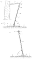
図1に、鋸刃駆動ユニットを持つタイプの高所鋸の構成を模式的に例示する。支持棒1の先に鋸刃駆動ユニット2が取り付けられている。鋸刃駆動ユニット2は、その先端に鋸刃3を備えており、鋸刃3は例えば鋸刃駆動ユニット2に内蔵されるシリンダおよびピストンよって駆動し往復運動するようになっている(後述の図6参照)。その鋸刃3の往復運動により樹木の枝37を切断する場合を例示してある。支持棒1は傾動可能なように、例えば支持台4を介して地面5に取り付けられる。支持台4は地面に対する相対位置が一定に保持できる「支持体」である。図1(b)のように鋸刃や支持棒等の傾動部材の自重が被切断物に掛かるように、支持棒1の長手方向と水平面7とのなす角度Φを90°未満として作業を行うことができ、そうすることによって作業者が鋸刃を被切断物に押し当てる力が軽減される。
The altitude saw of the present invention has a mechanism for tilting a support bar to which a saw blade or a saw blade drive unit is attached.
FIG. 1 schematically illustrates a configuration of an altitude saw having a saw blade drive unit. A saw
本発明の高所鋸には、支持棒1が一平面内に拘束されて傾動するような機構を持たせることができる。この傾動可能な平面を本明細書では「傾動平面」と呼び、図1中には符号6で示されている。図1(a)は傾動平面6および水平面7に平行な方向から見たもの、図1(b)は図1(a)に対し直角の方向(図1(a)中に示したA方向)から見たものである。
傾動平面6は水平面7に対してθの角度をなす平面であり、高所鋸の使用時には傾動平面6はθが90±45°の範囲にある一平面に固定される。すなわち、支持棒1は1つの傾動平面6内に拘束されて動くことができる状態で使用される。支持棒1は通常、傾動平面6に対して若干の「遊び」を設けて支持台4などに取り付けられる。したがって本発明で「傾動平面内に拘束されて」とは、支持棒1の取り付け機構における「遊び」による変動範囲を許容する。
The height saw of the present invention can be provided with a mechanism in which the support rod 1 is restrained in a single plane and tilted. This tiltable plane is referred to herein as a “tilt plane” and is indicated by the
The tilting
鋸刃3は切り進む方向(切断方向)が傾動平面6に平行な方向に概略固定されるように鋸刃駆動ユニット2に取り付けられている。すなわち鋸刃3は鋸刃駆動ユニット2に対して往復運動するが、その際、刃の向きが往復運動方向を軸として回転せず、概略一定方向の向きに固定されるようになっている。ここで「概略」とは刃の向きを固定する機構における「遊び」による変動範囲を許容する意味である。支持棒1が傾動平面6内に拘束されて動くことにより、切断方向が一定に拘束され、安定した切断作業が可能になる。つまり作業者は切断作業中に切断方向のコントロールから開放され、従来の手持ち鋸等と比べ極めて容易に正確な切断が可能になる。
The
なお、支持棒1は多少たわむことがある。その場合、前記傾動平面6は支持棒1の下端と上端を結ぶ直線が含まれる平面として捉え、前記の角度θを設定すればよい。また、上記角度Φについては、支持棒1の下端と上端を結ぶ直線の方向を支持棒1の長手方向として設定すればよい。
The support rod 1 may bend slightly. In this case, the
傾動平面6と水平面7とのなす角度θは、被切断物の状態に応じて最適な角度に設定する。ただし、その角度があまり小さくなると作業性が低下するので、90±45°の範囲で固定できるような構造とすることが望ましい。90±30°の範囲で固定できる構造としてもよく、特に安定した1人作業を重視する場合は90±20°の範囲で固定できる構造とすることが効果的である。
The angle θ formed by the
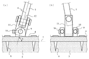
図2に、図1のタイプの高所鋸について、支持棒1を「支持体」である支持台4に取り付ける機構を模式的に例示する。図2(a)および図2(b)はそれぞれ図1(a)および図1(b)に対応する方向から見た図である。地面5には支持台4が例えばアンカー8により固定されている。なお、支持台4が高所鋸全体の質量に対して十分大きい質量およびサイズを有している場合には、支持台4を地面に置くだけでも地面に対する位置が一定に保持できる「支持体」として機能する。支持台4には固定軸受け9が取り付けられており、その固定ねじ10を締め付けることにより軸38を有する支持棒取り付け治具11を水平面7に対しθの角度で固定できるようになっている。角度θは90±45°の範囲で調整できる。支持棒取り付け治具11には支持棒1がピン12を介して取り付けられている。支持棒1はピン12を軸として傾動させることができる。このとき、支持棒1を水平面7に対しθの角度をなす傾動平面6の平面内に拘束して傾動させることができる。
FIG. 2 schematically illustrates a mechanism for attaching the support rod 1 to the support base 4 as a “support” for the high-end saw of the type shown in FIG. 2 (a) and 2 (b) are views seen from directions corresponding to FIGS. 1 (a) and 1 (b), respectively. The support 4 is fixed to the
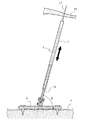
図3には、往復運動する支持棒1の上端に往復運動鋸刃13が固定されているタイプの高所鋸の構造を模式的に例示する。この支持棒1は少なくとも下端付近が中空パイプで構成されている。「支持体」である支持台4には、ガイド棒14が傾動平面6内に拘束されて傾動できるように取り付けられている。その取り付け機構としては例えば図2と類似の機構が採用できる。支持棒1はその中空部にガイド棒14を挿入することにより支持台4に取り付けられ、ガイド棒14とともに傾動平面6内に拘束されて傾動可能である。かつ支持棒1はガイド棒14に沿って図3中に矢印で示した長手方向に往復運動できるようになっている。また、支持棒1がガイド棒14を軸として回転しないように回転防止機構が設けられている。つまり、刃の切り進む向きは傾動平面6に平行な方向に概略固定される。このタイプの高所鋸では、作業者が支持棒1を往復運動させることにより被切断物34を切断する。その際、往復運動鋸刃13の動作は傾動平面6内に拘束されるので、一定方向に被切断物34を切り進めることができる。傾動平面6と水平面7のなす角度θは90±20°の範囲に設定すると作業がしやすく、90±15°の範囲に設定することが一層好ましい。図3はθ=90−15°=75°の例である。なお、支持棒1とガイド棒14の接触がベアリングを介して行われるようにすると、支持棒1の動作が一層スムーズになる。
FIG. 3 schematically illustrates the structure of an altitude saw of the type in which a
図4には、図3と同様に往復運動する支持棒1の上端に往復運動鋸刃13が固定されているが、支持棒1の下端付近を中空パイプ状のガイド鞘16の中に挿入するタイプの高所鋸の構造を模式的に例示する。支持台4にはガイド鞘16が、傾動平面6内に拘束されて傾動できるように取り付けられている。その取り付け機構としては例えば図2と類似の機構が採用できる。支持棒1は下端付近をガイド鞘16に挿入することにより支持台4に取り付けられ、ガイド鞘16とともに傾動平面6内に拘束されて傾動可能であり、かつガイド鞘16に沿って支持棒1の長手方向に往復運動できるようになっている。また、支持棒1がガイド鞘16を軸として回転しないように回転防止機構が設けられている。つまり、刃の切り進む向きは傾動平面6に平行な方向に概略固定される。この高所鋸は図3のタイプと同様に、作業者が支持棒1を往復運動させることにより、一定方向に被切断物34を切り進めることができる。この場合も傾動平面6と水平面7のなす角度θは90±20°の範囲に設定すると作業がしやすく、90±15°の範囲に設定することが一層好ましい。図4はθ=90−15°=75°の例である。なお、支持棒1とガイド鞘16の接触がベアリングを介して行われるようにすると、支持棒1の動作が一層スムーズになる。
In FIG. 4, the
図5に、高所鋸の支持棒を樹木の幹に取り付ける機構を模式的に例示する。図5(a)は水平面に対し鉛直方向から見た図、図5(b)は水平面に対し平行方向から見た図である。この例では、樹木の幹21の周囲に「支持体」として機能する調整台22を固定し、調整台22の上面に設けられた溝23を利用して支持棒1を調整台22に取り付けるようにしてある。調整台22はα部材とβ部材に2分割されており、中央に樹木の幹21を挟んだ状態で両部材を図示されていないボルト・ナット等で締結し、さらにスパイク27を樹木の幹21にねじ込んで樹木に固定する。
FIG. 5 schematically illustrates a mechanism for attaching an altitude saw support rod to a tree trunk. FIG. 5A is a diagram viewed from a direction perpendicular to the horizontal plane, and FIG. 5B is a diagram viewed from a direction parallel to the horizontal plane. In this example, an
溝23は樹木の幹21の周囲に円周状に形成してあるので、調整台22を一旦樹木の幹21に固定してしまえば、支持棒1を樹木の幹21の周囲の任意位置に取り付けることができる。その取り付け方法としては、例えばボールヘッド治具24を溝23にワッシャ26を介してナットによりねじ止めする。ボールヘッド治具24はカメラを三脚に固定する際に使用されている自由雲台と同様の機構を有するものが使用でき、その雲台に相当する部位にヘッド金具25を有している。ヘッド金具25に支持棒1の下端付近をピン12を介して取り付けることにより、支持棒1はピン12を軸として傾動可能になる。ボールヘッド治具24の固定ねじ10を締め付けることによりヘッド金具25を所定の傾き角度に固定することができ、支持棒1は水平面7に対しθ(θは90±45°)の角度を有する傾動平面6内で傾動できるようになる。
Since the
図6(a)に示す構造の高所鋸を作製した。この高所鋸は、支持棒1の上部に鋸刃駆動ユニット2が固定されており、ピストン29の動作により鋸刃3が図中に矢印で示した方向に往復運動する。鋸刃駆動ユニット2には鋸刃3がその往復運動方向を軸として回転しないような機構が設けられている。支持棒1は釣り竿に使用されているカーボンファイバー製のものを使用し、多段階のパイプ部材を伸長して長さ約12mとした。ピストン29は空気圧で駆動するようになっている。鋸刃駆動ユニット2のシリンダー30にはチューブ31が接続され、チューブ31は動力源であるポンプ32につながっている。これらの内部には流体として空気が充填されている。流体としてオイルも使用可能であるが、粘性を有することから気体を使用することが好ましい。作業者33が足踏み式でポンプ32に圧力を加えるとチューブ31からシリンダー30内に空気が流入してピストン29が「往」運動し、それに連動して動く鋸刃3によって被切断物の切断が進行する。同時に鋸刃駆動ユニット2内に設けられているバネ35がピストン29の「往」運動により縮み、バネ35に弾性エネルギーが蓄積される。次に、作業者33がポンプ32に加える圧力を緩めると、バネ35がその弾性エネルギーによって伸びることによりピストン29および鋸刃3を「復」運動させ、シリンダー30内の空気はチューブ31に戻り、ポンプ32も圧力を加える前の状態に復帰する。チューブ31は支持棒1のパイプ内に内蔵してある。
An altitude saw having the structure shown in FIG. In this high-end saw, the saw
この高所鋸は作業者33がポンプ32を押し下げる1動作によって鋸刃3が1回「往」運動し、鋸刃3に切断力が発生する。したがって、鋸刃3は押したときに切れるタイプのものが取り付けてある。もし、引いたときに切れるタイプの鋸刃を使用するのであれば、図6(b)のように逆向きに取り付ければよい。また、図6(a)のものは鋸刃3の運動方向が支持棒1の長さ方向とほぼ平行であるが、支持棒1と鋸刃駆動ユニット2の取り付け角度を変更する機構を用いれば使用態様に応じて鋸刃運動方向を調整できる。ポンプ32とシリンダー30との間の動力伝達媒体(流体)としては種々の気体が使用できるが、空気(圧縮空気を含む)が最も利用しやすい。
In this high-end saw, the
支持棒1は下端の治具36によって支持台4に取り付けられている。この治具36は支持棒1を水平面に対し任意の角度をなす傾動平面内に拘束して傾動できる機構を有している。支持台4はアンカー8により地面5に固定した。
The support rod 1 is attached to the support base 4 by a
この高所鋸を、約12mの高さにある樹木の枝37の切断に供した。傾動平面を地面に対する角度θが約90−15°=75°となるように固定し、鋸刃3が被切断物である樹木の枝37にほぼ垂直に当たるようにした。傾動平面内において地面5と支持棒1とのなす角度Φは切断を開始する時点で約80°とした。支持棒1と鋸刃駆動ユニット2の重量を利用して鋸刃3が被切断物である樹木の枝37にもたれ掛かるようにしながら切断を行った。作業者33は支持棒1を手で軽く支えながらポンプ32を足で踏み込む動作を繰り返すことにより、樹木の枝37をその長さ方向に対しほぼ垂直方向に切断した。鋸刃3は往復運動方向の軸まわりに回転せず、かつ傾動平面内に拘束されて傾動するので、1人作業で容易に正確な切断が可能であった。
This height saw was used for cutting a
1 支持棒
2 鋸刃駆動ユニット
3 鋸刃
4 支持台
5 地面
6 傾動平面
7 水平面
8 アンカー
9 固定軸受け
10 固定ねじ
11 支持棒取り付け治具
12 ピン
13 往復運動鋸刃
14 ガイド棒
16 ガイド鞘
21 樹木の幹
22 調整台
23 溝
24 ボールヘッド治具
25 ヘッド金具
26 ワッシャ
27 スパイク
29 ピストン
30 シリンダー
31 チューブ
32 ポンプ
33 作業者
34 被切断物
35 バネ
36 治具
37 樹木の枝
38 軸
DESCRIPTION OF SYMBOLS 1
Claims (4)
Priority Applications (1)
| Application Number | Priority Date | Filing Date | Title |
|---|---|---|---|
| JP2006029070A JP4787623B2 (en) | 2006-02-06 | 2006-02-06 | High altitude saw |
Applications Claiming Priority (1)
| Application Number | Priority Date | Filing Date | Title |
|---|---|---|---|
| JP2006029070A JP4787623B2 (en) | 2006-02-06 | 2006-02-06 | High altitude saw |
Publications (3)
| Publication Number | Publication Date |
|---|---|
| JP2007209201A JP2007209201A (en) | 2007-08-23 |
| JP2007209201A5 JP2007209201A5 (en) | 2009-03-26 |
| JP4787623B2 true JP4787623B2 (en) | 2011-10-05 |
Family
ID=38488147
Family Applications (1)
| Application Number | Title | Priority Date | Filing Date |
|---|---|---|---|
| JP2006029070A Expired - Fee Related JP4787623B2 (en) | 2006-02-06 | 2006-02-06 | High altitude saw |
Country Status (1)
| Country | Link |
|---|---|
| JP (1) | JP4787623B2 (en) |
Family Cites Families (9)
| Publication number | Priority date | Publication date | Assignee | Title |
|---|---|---|---|---|
| JPS49130052U (en) * | 1973-03-19 | 1974-11-08 | ||
| JPS5034360U (en) * | 1973-05-17 | 1975-04-12 | ||
| JPS51123952U (en) * | 1975-04-03 | 1976-10-07 | ||
| JPS5435049A (en) * | 1977-08-20 | 1979-03-14 | Tadahiro Yuuki | Preventing method and device for vibrating of upper portion of branch cutter |
| JPS5767564U (en) * | 1980-10-11 | 1982-04-22 | ||
| JPS6017659U (en) * | 1983-07-15 | 1985-02-06 | 豊興工業株式会社 | portable pruning machine |
| JPS61191759U (en) * | 1985-05-23 | 1986-11-28 | ||
| JPS6297552U (en) * | 1985-12-09 | 1987-06-22 | ||
| JP2869035B2 (en) * | 1996-04-17 | 1999-03-10 | 柾巳 岸本 | Auxiliary legs for saws for high branches |
-
2006
- 2006-02-06 JP JP2006029070A patent/JP4787623B2/en not_active Expired - Fee Related
Also Published As
| Publication number | Publication date |
|---|---|
| JP2007209201A (en) | 2007-08-23 |
Similar Documents
| Publication | Publication Date | Title |
|---|---|---|
| US7913403B1 (en) | Reciprocating pruning saw | |
| US4188935A (en) | Roller handle for saw | |
| US8898913B1 (en) | Masonry circular saw stabilizing and supporting shoe | |
| EP1971752B1 (en) | Assist for raise lower mechanism for a concrete saw | |
| US20110247224A1 (en) | Cable saw system | |
| AU688020B2 (en) | Portable sawmill | |
| US10532485B2 (en) | Positioning system | |
| JP2007209201A (en) | High-place saw | |
| US7181850B2 (en) | Saber saw having blade tiltable toward workpiece relative to saw body when cutting | |
| JP5795608B2 (en) | Altitude pruning machine | |
| KR20170128695A (en) | Apparatus for cutting a rubber hose | |
| US20170334092A1 (en) | Cutting arm assembly for tile cutter | |
| US9919413B2 (en) | Chainsaw mount device | |
| JP3559686B2 (en) | Balance support device for operation rod for power distribution work | |
| CN202026622U (en) | Branch pruning device | |
| JP4172313B2 (en) | Steel cutting machine and steel cutting method | |
| US20080289472A1 (en) | Skidloader mounted timbersaw attachment | |
| DE805327C (en) | Pruning saw | |
| CN213941953U (en) | Fire monitor with pitching load light-load design | |
| JP2011120564A (en) | Elongated handle for high branch cutting saw | |
| JP7563869B1 (en) | Remote controlled felling device for core stopping | |
| JP6313368B2 (en) | High branch saw | |
| CN222263712U (en) | A telescopic structure capable of adjusting tube length | |
| RU2802067C1 (en) | Mobile device for trimming branches of tall trees | |
| KR200343115Y1 (en) | Apparatus for harvesting a fruit |
Legal Events
| Date | Code | Title | Description |
|---|---|---|---|
| A521 | Written amendment |
Free format text: JAPANESE INTERMEDIATE CODE: A523 Effective date: 20090205 |
|
| A621 | Written request for application examination |
Free format text: JAPANESE INTERMEDIATE CODE: A621 Effective date: 20090205 |
|
| A977 | Report on retrieval |
Free format text: JAPANESE INTERMEDIATE CODE: A971007 Effective date: 20101111 |
|
| A131 | Notification of reasons for refusal |
Free format text: JAPANESE INTERMEDIATE CODE: A131 Effective date: 20101116 |
|
| A521 | Written amendment |
Free format text: JAPANESE INTERMEDIATE CODE: A523 Effective date: 20110114 |
|
| TRDD | Decision of grant or rejection written | ||
| A01 | Written decision to grant a patent or to grant a registration (utility model) |
Free format text: JAPANESE INTERMEDIATE CODE: A01 Effective date: 20110712 |
|
| A01 | Written decision to grant a patent or to grant a registration (utility model) |
Free format text: JAPANESE INTERMEDIATE CODE: A01 |
|
| A61 | First payment of annual fees (during grant procedure) |
Free format text: JAPANESE INTERMEDIATE CODE: A61 Effective date: 20110715 |
|
| R150 | Certificate of patent or registration of utility model |
Free format text: JAPANESE INTERMEDIATE CODE: R150 |
|
| FPAY | Renewal fee payment (event date is renewal date of database) |
Free format text: PAYMENT UNTIL: 20140722 Year of fee payment: 3 |
|
| R250 | Receipt of annual fees |
Free format text: JAPANESE INTERMEDIATE CODE: R250 |
|
| LAPS | Cancellation because of no payment of annual fees |