JP4798024B2 - Television receiver, television receiver - Google Patents
Television receiver, television receiver Download PDFInfo
- Publication number
- JP4798024B2 JP4798024B2 JP2007057113A JP2007057113A JP4798024B2 JP 4798024 B2 JP4798024 B2 JP 4798024B2 JP 2007057113 A JP2007057113 A JP 2007057113A JP 2007057113 A JP2007057113 A JP 2007057113A JP 4798024 B2 JP4798024 B2 JP 4798024B2
- Authority
- JP
- Japan
- Prior art keywords
- card
- fan
- temperature
- television receiver
- signal
- Prior art date
- Legal status (The legal status is an assumption and is not a legal conclusion. Google has not performed a legal analysis and makes no representation as to the accuracy of the status listed.)
- Expired - Fee Related
Links
Images



Classifications
-
- H—ELECTRICITY
- H04—ELECTRIC COMMUNICATION TECHNIQUE
- H04N—PICTORIAL COMMUNICATION, e.g. TELEVISION
- H04N21/00—Selective content distribution, e.g. interactive television or video on demand [VOD]
- H04N21/40—Client devices specifically adapted for the reception of or interaction with content, e.g. set-top-box [STB]; Operations thereof
- H04N21/47—End-user applications
- H04N21/482—End-user interface for programme selection
-
- H—ELECTRICITY
- H04—ELECTRIC COMMUNICATION TECHNIQUE
- H04N—PICTORIAL COMMUNICATION, e.g. TELEVISION
- H04N21/00—Selective content distribution, e.g. interactive television or video on demand [VOD]
- H04N21/40—Client devices specifically adapted for the reception of or interaction with content, e.g. set-top-box [STB]; Operations thereof
- H04N21/41—Structure of client; Structure of client peripherals
- H04N21/418—External card to be used in combination with the client device, e.g. for conditional access
- H04N21/4181—External card to be used in combination with the client device, e.g. for conditional access for conditional access
-
- H—ELECTRICITY
- H04—ELECTRIC COMMUNICATION TECHNIQUE
- H04N—PICTORIAL COMMUNICATION, e.g. TELEVISION
- H04N21/00—Selective content distribution, e.g. interactive television or video on demand [VOD]
- H04N21/40—Client devices specifically adapted for the reception of or interaction with content, e.g. set-top-box [STB]; Operations thereof
- H04N21/41—Structure of client; Structure of client peripherals
- H04N21/426—Internal components of the client ; Characteristics thereof
-
- H—ELECTRICITY
- H04—ELECTRIC COMMUNICATION TECHNIQUE
- H04N—PICTORIAL COMMUNICATION, e.g. TELEVISION
- H04N21/00—Selective content distribution, e.g. interactive television or video on demand [VOD]
- H04N21/40—Client devices specifically adapted for the reception of or interaction with content, e.g. set-top-box [STB]; Operations thereof
- H04N21/43—Processing of content or additional data, e.g. demultiplexing additional data from a digital video stream; Elementary client operations, e.g. monitoring of home network or synchronising decoder's clock; Client middleware
- H04N21/438—Interfacing the downstream path of the transmission network originating from a server, e.g. retrieving encoded video stream packets from an IP network
- H04N21/4383—Accessing a communication channel
-
- H—ELECTRICITY
- H04—ELECTRIC COMMUNICATION TECHNIQUE
- H04N—PICTORIAL COMMUNICATION, e.g. TELEVISION
- H04N21/00—Selective content distribution, e.g. interactive television or video on demand [VOD]
- H04N21/40—Client devices specifically adapted for the reception of or interaction with content, e.g. set-top-box [STB]; Operations thereof
- H04N21/43—Processing of content or additional data, e.g. demultiplexing additional data from a digital video stream; Elementary client operations, e.g. monitoring of home network or synchronising decoder's clock; Client middleware
- H04N21/442—Monitoring of processes or resources, e.g. detecting the failure of a recording device, monitoring the downstream bandwidth, the number of times a movie has been viewed, the storage space available from the internal hard disk
- H04N21/44231—Monitoring of peripheral device or external card, e.g. to detect processing problems in a handheld device or the failure of an external recording device
-
- H—ELECTRICITY
- H04—ELECTRIC COMMUNICATION TECHNIQUE
- H04N—PICTORIAL COMMUNICATION, e.g. TELEVISION
- H04N21/00—Selective content distribution, e.g. interactive television or video on demand [VOD]
- H04N21/40—Client devices specifically adapted for the reception of or interaction with content, e.g. set-top-box [STB]; Operations thereof
- H04N21/43—Processing of content or additional data, e.g. demultiplexing additional data from a digital video stream; Elementary client operations, e.g. monitoring of home network or synchronising decoder's clock; Client middleware
- H04N21/442—Monitoring of processes or resources, e.g. detecting the failure of a recording device, monitoring the downstream bandwidth, the number of times a movie has been viewed, the storage space available from the internal hard disk
- H04N21/4424—Monitoring of the internal components or processes of the client device, e.g. CPU or memory load, processing speed, timer, counter or percentage of the hard disk space used
-
- H—ELECTRICITY
- H04—ELECTRIC COMMUNICATION TECHNIQUE
- H04N—PICTORIAL COMMUNICATION, e.g. TELEVISION
- H04N21/00—Selective content distribution, e.g. interactive television or video on demand [VOD]
- H04N21/40—Client devices specifically adapted for the reception of or interaction with content, e.g. set-top-box [STB]; Operations thereof
- H04N21/47—End-user applications
- H04N21/488—Data services, e.g. news ticker
- H04N21/4882—Data services, e.g. news ticker for displaying messages, e.g. warnings, reminders
-
- H—ELECTRICITY
- H04—ELECTRIC COMMUNICATION TECHNIQUE
- H04N—PICTORIAL COMMUNICATION, e.g. TELEVISION
- H04N5/00—Details of television systems
- H04N5/76—Television signal recording
- H04N5/907—Television signal recording using static stores, e.g. storage tubes or semiconductor memories
Landscapes
- Engineering & Computer Science (AREA)
- Multimedia (AREA)
- Signal Processing (AREA)
- Computer Networks & Wireless Communication (AREA)
- Databases & Information Systems (AREA)
- Automation & Control Theory (AREA)
- Human Computer Interaction (AREA)
- Two-Way Televisions, Distribution Of Moving Picture Or The Like (AREA)
Description
本発明は、デスクランブラが内蔵されたICカードを着脱可能なテレビジョン受像機およびテレビジョン受信機に関するものである。 The present invention relates to a television receiver and a television receiver in which an IC card with a built-in descrambler can be attached and detached.
例えば北米地域で送信されるデジタルケーブルテレビ放送の有料チャンネルの放送信号は、スクランブル(暗号化処理)されている。この種の放送チャンネルの映像を対応する音声とともに視聴するには、スクランブルされた放送信号をデスクランブル(暗号の復号処理)しなければならない。デスクランブルするためのデスクランブラ(信号処理回路)は、一般にPCMCIA(Personal Computer Memory Card International Association)等の規格に準拠したICカードに内蔵されている。このため、北米向けのテレビジョン受像機、光ディスクレコーダやハードディスクレコーダといった映像機器、またはSTB(Set Top Box)等のようなテレビジョン受信機には、上記ICカードを着脱するカードスロットが搭載されている(例えば特許文献3参照)。このテレビジョン受信機において、カードスロットに装着されたICカードに電圧を供給して、デスクランブラ等の回路を動作させると、ICカードが発熱する。北米のデジタルケーブル規格では、ICカードが熱により故障するのを防ぐために、テレビジョン受信機のメイン電源のオンまたはオフにかかわらず、常にICカードの温度を65℃以下に保つことが規定されている。 For example, broadcast signals of pay channels for digital cable television broadcast transmitted in North America are scrambled (encrypted). In order to view the video of this type of broadcast channel together with the corresponding audio, the scrambled broadcast signal must be descrambled (encryption decryption process). A descrambler (signal processing circuit) for descrambling is generally built in an IC card conforming to a standard such as PCMCIA (Personal Computer Memory Card International Association). For this reason, television receivers for North America, video equipment such as optical disk recorders and hard disk recorders, or television receivers such as STB (Set Top Box) are equipped with a card slot for attaching and detaching the IC card. (For example, refer to Patent Document 3). In this television receiver, when a voltage is supplied to an IC card installed in a card slot and a circuit such as a descrambler is operated, the IC card generates heat. The North American digital cable standard stipulates that the temperature of the IC card is always kept below 65 ° C regardless of whether the main power of the television receiver is turned on or off in order to prevent the IC card from being damaged by heat. Yes.
一方、テレビジョン受信機に、内部の温度を計測する温度センサと、内部を冷却するファンとを内蔵することが一般的に行われている(例えば特許文献1および特許文献2参照)。特許文献1では、温度センサの計測温度に基づいてファンの回転数を制御し、ファンが回転していないことまたは温度センサの計測温度が上限値を越えたことを検出すると、CATVセンタに異常を通報して、警報を出力し、CATVセンタからの応答を受けると、各部への電源の供給を遮断する。特許文献2では、各放送チャンネルの信号レベルをレベルメータで計測し、温度センサの計測温度に基づいてファンへの電圧供給元を切り替え、温度センサの計測温度がレベルメータの動作可能温度範囲から外れると、レベルメータへの電源の供給を停止し、システム管理者に無線電話で通報する。また、特許文献3では、ICカードの着脱をカード検出回路で検出し、受信した放送信号に試験信号を多重化してICカードへ入力し、ICカードからの出力信号から試験信号を検出できなければ、ICカードが故障したと判定して、該判定結果をテレビ画面に表示し、ICカードを本体から電気的に切り離し、該故障の影響が受信機全体に及ぶのを防止する。
On the other hand, a television receiver is generally built with a temperature sensor that measures the internal temperature and a fan that cools the interior (see, for example,
上述したICカードを冷却するために、ファンをテレビジョン受信機に内蔵した場合、ファンが故障して正常に動作しなくなると、ICカードが熱により故障するおそれがある。また、上述した特許文献1〜3では、ICカードの正確な温度を検出できないため、ICカードの温度が高くなったときに適切に対処できず、ICカードの熱による故障を防げないおそれがある。
When a fan is built in a television receiver to cool the above-described IC card, the IC card may be damaged by heat if the fan fails and does not operate normally. Further, in
本発明は、上述した問題点を解決するものであって、その課題とするところは、ICカードが熱により故障するのを防止することが可能なテレビジョン受信機およびテレビジョン受像機を提供することにある。 The present invention solves the above-described problems, and an object thereof is to provide a television receiver and a television receiver capable of preventing the IC card from being damaged by heat. There is.
本発明では、スクランブルされた信号をデスクランブルするデスクランブラを内蔵したICカードが着脱可能なカードスロットと、ファンと、温度センサと、記憶手段と、各部の動作を制御する制御手段とを備えたテレビジョン受信機において、記憶手段には、カードスロットに装着されたICカードの温度と温度センサの計測温度との相関を示す情報が予め記憶されていて、制御手段は、ファンを回転させてICカードを冷却し、記憶手段の相関情報と温度センサの計測温度とに基づいてICカードの温度を検出し、ICカードの温度が許容温度を上回ったときに、ファンが故障したと判断し、ICカードのデスクランブラでデスクランブルする可能性がある受信信号に基づく映像音声信号を出力する一方のモード中であれば、ICカードのデスクランブラでデスクランブルする可能性がない受信信号に基づく映像音声信号を出力する他方のモードへ切り替え、ICカードへの供給電圧をオフし、一方のモードへの切り替えを禁止する。 The present invention includes a card slot in which an IC card incorporating a descrambler that descrambles a scrambled signal is detachable, a fan, a temperature sensor, a storage unit, and a control unit that controls the operation of each unit. In the television receiver, the storage means stores in advance information indicating the correlation between the temperature of the IC card mounted in the card slot and the temperature measured by the temperature sensor, and the control means rotates the fan to make the IC The card is cooled, the temperature of the IC card is detected based on the correlation information of the storage means and the temperature measured by the temperature sensor. When the temperature of the IC card exceeds the allowable temperature, it is determined that the fan has failed. If you are in one mode that outputs video and audio signals based on received signals that may be descrambled by the card's descrambler, the IC card Switching to the other mode for outputting video and audio signals based on the received signal is not likely to descramble descrambler, turns off the supply voltage to the IC card, to prohibit switching to one mode.
このようにすると、テレビジョン受信機において、ICカードの温度と温度センサの計測温度との相関情報と、温度センサの計測温度とに基づいて、カードスロットに装着されたICカードの正確な温度を検出することができる。このため、ICカードの温度が許容温度を上回ったときに、一方のモードから他方のモードへ切り替えたり、ICカードへの供給電圧をオフしたり、一方のモードへの切り替えを禁止したりして、ICカードの動作を停止して発熱を抑制するように適切に対処することができる。よって、ファンが故障して正常に動作しなくなっても、ICカードが熱により故障するのを防止することが可能となる。また、前述の特許文献1、2では、ファンが故障したり内部温度がある温度を越えたりすると、各部への電源の供給を停止するので、テレビジョン受信機が使用できなくなるが、上記によると、ファンが故障したりICカードの温度が許容温度を上回ったりしても、ICカードを保護しつつ、テレビジョン受信機を他方のモードで使用することが可能となる。
In this way, in the television receiver, based on the correlation information between the temperature of the IC card and the measured temperature of the temperature sensor, and the measured temperature of the temperature sensor, the accurate temperature of the IC card installed in the card slot is obtained. Can be detected. For this reason, when the temperature of the IC card exceeds the allowable temperature, switching from one mode to the other mode, turning off the supply voltage to the IC card, or prohibiting switching to one mode is performed. Therefore, it is possible to appropriately cope with the operation of the IC card by stopping the operation and suppressing the heat generation. Therefore, even if the fan fails and does not operate normally, it is possible to prevent the IC card from being damaged by heat. Moreover, in the above-mentioned
また、本発明では、上記テレビジョン受信機において、制御手段は、ICカードの温度が許容温度を上回って、モードの切り替えとICカードへの供給電圧のオフを行った後、ICカードの抜き取りとファンの交換を促すような通知を行う。 In the present invention, in the above television receiver, the control means may be configured to remove the IC card after switching the mode and turning off the supply voltage to the IC card when the temperature of the IC card exceeds the allowable temperature. Provide notification to encourage fan replacement.
このようにすると、ユーザにファンの故障を気付かせて、ICカードをカードスロットから抜き取ることや、サポートセンタにてファンを正常なものに交換することを、即座に行わせることができ、ICカードが熱により故障するのを一層防止することが可能となる。 This makes it possible for the user to notice the failure of the fan and to immediately remove the IC card from the card slot or replace the fan with a normal one at the support center. Can be further prevented from being damaged by heat.
また、本発明では、上記テレビジョン受信機において、制御手段は、ICカードの温度が許容温度を上回った後のメイン電源のオフ時に、各部の状態を記憶手段に記録し、メイン電源のオン時に、記憶手段から前回のメイン電源のオフ時の各部の状態の記録を読み込んで、該状態を継続する。 According to the present invention, in the television receiver, the control means records the state of each part in the storage means when the main power is turned off after the temperature of the IC card exceeds the allowable temperature, and when the main power is turned on. Then, a record of the state of each unit when the main power is turned off the last time is read from the storage means, and the state is continued.
このようにすると、ファンが故障している間は、何度メイン電源をオンしてテレビジョン受信機を起動させても、ICカードへの供給電圧がオンされず、一方のモードへの切り替えが禁止されるので、ICカードの動作が開始されず発熱が抑制され、ICカードが熱により故障するのを一層防止することが可能となる。また、メイン電源のオフ時にICカードの抜き取りとファンの交換を促す通知を行ったことを記憶手段に記憶し、その後のメイン電源のオン時に該通知を再び行うことで、ユーザが忘れていたり、ユーザが入れ代わったりしても、ファンの故障を気付かせて、ICカードの抜き取りやファンの交換を即座に行わせることができる。 In this way, while the fan is out of order, no matter how many times the main power is turned on and the television receiver is turned on, the supply voltage to the IC card is not turned on, and switching to one mode is possible. Since it is prohibited, the operation of the IC card is not started, heat generation is suppressed, and it is possible to further prevent the IC card from being damaged by heat. In addition, when the main power is turned off, the storage means stores a notification that prompts the user to remove the IC card and replace the fan, and when the main power is turned on again, the user forgets it. Even if the user is replaced, the failure of the fan can be noticed, and the removal of the IC card and the replacement of the fan can be performed immediately.
また、本発明では、上記テレビジョン受信機において、カードスロットへのICカードの装着を検出する装着検出手段と、ファンの回転数を検出する回転数検出手段とを備え、制御手段は、メイン電源のオン時に、カードスロットにICカードが装着されていれば、ファンへの供給電圧をオンし、ファンの回転数が一定の回転数以上になれば、ファンが交換されて正常動作中であると判断して、ICカードへの供給電圧をオンし、一方のモードへの切り替えを許可する。 According to the present invention, the television receiver includes a mounting detection unit that detects mounting of the IC card in the card slot, and a rotation speed detection unit that detects the rotation speed of the fan. When an IC card is inserted in the card slot, the supply voltage to the fan is turned on. If the fan rotation speed exceeds a certain rotation speed, the fan is replaced and operating normally. Judgment is made, the supply voltage to the IC card is turned on, and switching to one mode is permitted.
このようにすると、故障したファンが正常なファンに交換されたことを検出して、即座にICカードを動作させて、テレビジョン受信機を一方のモードでも使用できるように復帰させることが可能となる。 In this way, it is possible to detect that the failed fan has been replaced with a normal fan, immediately operate the IC card, and return the television receiver so that it can be used in one mode. Become.
さらに、本発明の典型的な実施形態では、上記テレビジョン受信機は、上記構成に加えて、表示手段と音声出力手段とを備え、ケーブルテレビ放送信号、地上波放送信号、または外部の映像機器からの入力信号を受信し、該信号から映像信号と音声信号を取得して、該映像信号を表示手段へ出力して映像を表示し、該音声信号を音声出力手段へ出力して音声を出力するテレビジョン受像機から成る。このテレビジョン受像機において、制御手段は、ICカードの温度が許容温度を上回ったときに、ファンが故障したと判断し、ICカードのデスクランブラでデスクランブルする可能性があるケーブルテレビ放送信号に基づく映像を表示手段に表示しかつ音声を音声出力手段から出力する一方のモード中であれば、ICカードのデスクランブラでデスクランブルする可能性がない地上波放送信号または外部入力信号に基づく映像を表示手段に表示しかつ音声を音声出力手段から出力する他方のモードへ切り替え、ICカードへの供給電圧をオフし、ファンの故障を通知してICカードの抜き取りとファンの交換を促す表示を表示手段に表示し、一方のモードへの切り替えを禁止し、この後のメイン電源のオフ時に、各部の状態を記憶手段に記録する。また、制御手段は、メイン電源のオン時に、記憶手段から前回のメイン電源のオフ時の各部の状態の記録を読み込んで、該状態を継続し、装着検出手段によりICカードの装着を検出すると、ファンへの供給電圧をオンし、回転数検出手段によりファンの回転数が一定の回転数以上になったことを検出すると、ファンが交換されて正常動作中であると判断して、ICカードへの供給電圧をオンし、一方のモードへの切り替えを許可し、記憶手段から各部の状態の記録を消去する。 Further, in a typical embodiment of the present invention, the television receiver includes a display unit and an audio output unit in addition to the above configuration, and includes a cable TV broadcast signal, a terrestrial broadcast signal, or an external video device. The video signal and the audio signal are acquired from the signal, the video signal is output to the display means to display the video, and the audio signal is output to the audio output means to output the audio. It consists of a television receiver. In this television receiver, the control means determines that the fan has failed when the temperature of the IC card exceeds the allowable temperature, and generates a cable TV broadcast signal that may be descrambled by the descrambler of the IC card. Video based on a terrestrial broadcast signal or an external input signal that is not likely to be descrambled by the descrambler of the IC card, while in one mode of displaying video based on the display means and outputting audio from the audio output means Switch to the other mode that displays on the display means and outputs the sound from the sound output means, turns off the supply voltage to the IC card, displays a display notifying the fan failure and prompting the removal of the IC card and the fan replacement Display on the display, prohibit switching to one mode, and store the status of each part in the storage when the main power is turned off. To. Further, when the main power source is turned on, the control unit reads a record of the state of each unit at the time of the previous main power source off from the storage unit, continues the state, and detects the mounting of the IC card by the mounting detection unit. When the supply voltage to the fan is turned on and the rotation speed detection means detects that the fan rotation speed has reached a certain rotation speed or more, it is determined that the fan has been replaced and is operating normally, and is transferred to the IC card. The supply voltage is turned on, switching to one mode is permitted, and the record of the state of each part is erased from the storage means.
このようにすると、テレビジョン受像機において、カードスロットに装着されたICカードの正確な温度を検出できるので、ICカードの温度が許容温度を上回ったときに、ICカードの動作を停止して発熱を抑制するように適切に対処することができる。このため、ファンが故障して正常に動作しなくなっても、ICカードが熱により故障するのを防止することが可能となる。また、ICカードの動作を停止して、ケーブルテレビ放送の映像を表示し音声を出力する一方のモードでの使用のみを禁止するので、テレビジョン受像機を地上波放送または外部入力の映像を表示し音声を出力する他方のモードで使用して、該映像と音声を視聴して楽しむことが可能となる。また、ファンの故障を通知してICカードの抜き取りとファンの交換を促す表示を表示手段に表示させるので、ユーザに即座にファンの故障を気付かせて、ICカードの抜き取りとファンの交換を行わせることができる。また、ICカードの温度が許容温度を上回ったときの各部の状態を、次回起動したときに継続するので、ファンが故障している間は何度起動しても、ICカードの動作が開始されず発熱が抑制され、ICカードが熱により故障するのを防止することが可能となる。さらに、メイン電源のオン時にファンが正常なものに交換されたことを検出し、即座にICカードを動作させて、前回メイン電源オフ時の各部の状態の記録を消去するので、テレビジョン受像機を一方のモードでも使用可能に復帰させることができる。このため、以降はケーブルテレビ放送と地上波放送と外部入力のそれぞれの映像と音声を視聴して楽しむことが可能となる。 In this way, the television receiver can detect the exact temperature of the IC card installed in the card slot, so when the temperature of the IC card exceeds the allowable temperature, the operation of the IC card is stopped to generate heat. It is possible to appropriately deal with such a situation. For this reason, even if the fan fails and does not operate normally, it is possible to prevent the IC card from being damaged by heat. In addition, the operation of the IC card is stopped and the use of one mode that displays cable TV broadcast video and outputs sound is prohibited, so the television receiver displays terrestrial broadcast or external input video. However, it is possible to view and enjoy the video and audio when used in the other mode of outputting audio. In addition, the display unit displays a notification of fan failure and prompts the user to remove the IC card and replace the fan, so that the user can immediately notice the fan failure and remove the IC card and replace the fan. Can be made. In addition, since the state of each part when the IC card temperature exceeds the allowable temperature is continued at the next startup, the operation of the IC card is started no matter how many times it is started while the fan has failed. Heat generation is suppressed, and it is possible to prevent the IC card from being damaged by heat. Further, when the main power is turned on, it is detected that the fan has been replaced with a normal one, and the IC card is immediately operated to erase the record of the state of each part when the main power was last turned off. Can be returned to be usable in either mode. For this reason, it is possible to view and enjoy the video and audio of cable TV broadcast, terrestrial broadcast, and external input thereafter.
本発明によれば、ファンが故障しても、ICカードの正確な温度を検出して、ICカードの温度が許容温度を上回ったときに、ICカードの動作を停止して発熱を抑制するように適切に対処することができ、ICカードが熱により故障するのを防止することが可能となる。 According to the present invention, even if a fan breaks down, the accurate temperature of the IC card is detected, and when the temperature of the IC card exceeds the allowable temperature, the operation of the IC card is stopped to suppress heat generation. Therefore, it is possible to prevent the IC card from being damaged by heat.
図1は、テレビジョン受像機100のブロック図である。テレビジョン受像機100は、本発明におけるテレビジョン受像機とテレビジョン受信機の一実施形態を構成する。制御部1は、CPUとROMやRAM等のメモリとOSD(On Screen Display)回路2等から成る。制御部1は、テレビジョン受像機100の各部を制御する。制御部1は、本発明における制御手段の一実施形態を構成する。テレビジョン受像機100には、DVD(Digital Versatile Disc)やブルーレイディスク(Blu-ray Disc;登録商標)等の光ディスクを取り扱う光ディスクプレーヤ、光ディスクレコーダ、ハードディスクレコーダ等のような映像機器がケーブル等により接続される。それらの外部の映像機器から出力された信号(映像音声信号等)は、入力端子3からテレビジョン受像機100に入力される。入力端子3から入力される信号のことを、以下では外部入力信号という。テレビジョン受像機100には、デジタルケーブルテレビ放送信号または地上波放送信号を伝送するケーブル等が接続される。これらの放送信号(搬送波)は、入力端子4からテレビジョン受像機100に入力される。ケーブルテレビ放送の有料チャンネルの放送信号は、スクランブルされている。ケーブルテレビ放送の無料チャンネルの放送信号と地上波放送信号は、スクランブルされていない。
FIG. 1 is a block diagram of the
チューナ部5は、入力端子4を介して受信した放送信号より、選局されたチャンネルの周波数の信号を抽出して、MPEG(Moving Picture Experts Group)処理部6へ入力する。MPEG処理部6は、デモジュレータ7やデコーダ8等のような、MPEG処理を行うための各種信号処理回路から成る。カードスロット9は、ICカード10を着脱可能である。ICカード10は、PCMCIAの規格に準拠している。ICカード10には、スクランブルされたデジタルケーブルテレビ放送信号をデスクランブルするデスクランブラ(信号処理回路)11が内蔵されている。制御部1のカード検出用に割り当てられたGPIO(汎用I/Oポート)1bは、ICカード10の内蔵回路と接続されている。GPIO1bにかかる電圧レベルは、ICカード10がカードスロット9に装着されているときは高レベルになり、ICカード10がカードスロット9に装着されていないときは低レベルになる。制御部1は、GPIO1bの電圧レベルから、カードスロット9へのICカード10の装着の有無を検出する。制御部1のGPIO1bは、本発明における装着検出手段の一実施形態を構成する。これ以外に、装着検出手段としてマイクロスイッチやフォトセンサ等を用いてもよい。
The
MPEG処理部6へ入力された地上波放送信号は、デモジュレータ7で復調された後、デコーダ8で映像音声信号にデコードされて、A/V_SW12へ入力される。MPEG処理部6へ入力されたデジタルケーブルテレビ放送信号は、デモジュレータ7で復調された後、ICカード10を経由して、デコーダ8で映像音声信号にデコードされて、A/V_SW12へ入力される。ICカード10へ入力されたデジタルケーブルテレビ放送信号のうち、スクランブルされた信号だけがデスクランブラ11でデスクランブルされる。A/V_SW12は、信号スイッチ回路から成る。制御部1は、A/V処理部13へ入力する映像音声信号を、A/V_SW12によりMPEG処理部6からの入力信号または入力端子3からの外部入力信号のいずれかに切り替える。A/V処理部13は、入力されたデジタルの映像音声信号に対してアナログ変換等の処理を施して映像信号と音声信号を取得し、該映像信号を表示部14へ出力し、該音声信号を音声出力部15へ出力する。表示部14は、液晶ディスプレイ等から成り、本発明における表示手段の一実施形態を構成する。表示部14は、入力された映像信号に基づく映像を表示する。音声出力部15は、スピーカ等から成り、本発明における音声出力手段の一実施形態を構成する。音声出力部15は、入力された音声信号に基づく音声を出力する。A/V処理部13には、OSD回路2から映像信号が入力される。制御部1は、OSD回路2とA/V処理部13により、各種情報を表示部14にオンスクリーン表示する。
The terrestrial broadcast signal input to the
記憶部16は、揮発性または不揮発性のメモリ等から構成されている。記憶部16は、本発明における記憶手段の一実施形態を構成する。操作部17は、テレビジョン受像機100の本体前面に設けられた操作パネルと、リモコン(リモートコントローラ)と、リモコン受信回路等から成る。操作パネルとリモコンには、テレビジョン受像機100のメイン電源をON・OFFするスイッチやチャンネルキー等の各種キーが設けられている。温度センサ18は、カードスロット9の近傍に設けられている。温度センサ18が計測した温度は、制御部1のA/DまたはICCのポート1gに出力される。記憶部16には、カードスロット9に装着されたICカード10の温度と温度センサ18の計測温度との相関を示す情報D1が予め記憶されている。相関情報D1は、例えばテレビジョン受像機100の製造段階等で、カードスロット9に装着されたICカード10の温度を別の温度検出手段で計測し、かつ温度センサ18で温度を計測しながら、ファン20を回転させずに、ICカード10への供給電圧をONして、ICカード10にデジタルケーブル放送信号を入力して、デスクランブラ11を動作させ続けたときの、ICカード10の温度と温度センサ18の計測温度の対応関係を示すデータである。制御部1は、記憶部16の相関情報D1と温度センサ18の計測温度に基づいて、ICカード10の温度を検出する。また、制御部1は、後述するようにテレビジョン受像機100のメイン電源のOFF時に、各部の状態を示す情報(状態記録D2)を記憶部16に記録する。
The
SW19は、電圧スイッチ回路から成る。ICカード10を動作させるには、ICカード10の仕様に応じて3.3Vまたは5Vの電圧をICカード10に供給する必要がある。制御部1の3.3V供給用に割り当てられたGPIO1cと、5V供給用に割り当てられたGPIO1dは、それぞれSW19と接続されている。制御部1は、ICカード10の仕様に応じてGPIO1c、1dからSW19に対して、ICカード10への供給電圧3.3Vまたは5VをそれぞれON(通電)またはOFF(遮断)する制御信号を出力する。
The
ファン20は、カードスロット9の近傍に設けられている。ファン20は、内蔵するモータ21の駆動力により回転する。SW22は、電圧スイッチ回路から成る。制御部1の電圧供給用に割り当てられたGPIO1fは、SW22と接続されている。制御部1は、GPIO1fからSW22に対して、ファン20への供給電圧をONまたはOFFしたり供給電圧のレベルを変えたりする制御信号を出力する。制御部は、ファン20を回転させて、ICカード10を冷却する。また、制御部1は、ICカード10の温度に基づいてファン20の回転数を制御する。制御部1の回転数検出用に割り当てられたGPIO1eはモータ21と接続されている。制御部1は、モータ21の駆動電流レベルをGPIO1eより検出し、該レベルに基づいてファン20の回転数を検出する。制御部1のGPIO1eは、本発明における回転数検出手段の一実施形態を構成する。これ以外に、回転数検出手段としてエンコーダ等を用いてもよい。
The
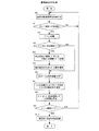
図2は、テレビジョン受像機100で行う異常検出対応処理の手順を示すフローチャートである。各処理は制御部1が実行する。テレビジョン受像機100が起動した後、デジタルケーブルテレビ放送信号、地上波放送信号、または外部入力信号のいずれかを受信して、該信号に基づく映像を表示部14に表示しかつ音声を音声出力部15から出力する通常の映像音声出力動作中に(ステップS0)、制御部1は、記憶部16の相関情報D1と温度センサ18の生(ライブ)の計測温度とに基づいて、ICカード10の温度を周期的に検出する。通常の映像音声出力動作中は、カードスロット9にICカード10が装着され、該ICカード10への供給電圧がONされ、ファン20が回転してICカード10を冷却している。
FIG. 2 is a flowchart showing a procedure of abnormality detection handling processing performed by the
ファン20が正常に動作していないため、ICカード10の温度が予め設定した許容温度(例えば、65℃)を上回ると(ステップS1:YES)、制御部1はファン20が故障したと判断する(ステップS2)。そして、制御部1は、このときICカード10のデスクランブラ11でデスクランブルする可能性があるケーブルテレビ放送信号に基づく映像を表示部14に表示しかつ音声を音声出力部15から出力するケーブルテレビ放送視聴モード中であれば(ステップS3:YES)、デスクランブラ11でデスクランブルする可能性がない地上波放送信号または外部入力信号に基づく映像を表示部14に表示しかつ音声を音声出力部15から出力する地上波放送視聴モードまたは外部入力視聴モードへ切り替える(ステップS4)。上記において、デスクランブラ11でデスクランブルする可能性があるケーブルテレビ放送信号とは、実際にスクランブルされているか否かにかかわらず、ICカード10へ入力させることが定められているケーブルテレビ放送の全ての放送信号のことである。切り替え先のモードは、予め設定されて記憶部16に記憶されている。また、各種設定画面において、ユーザが切り替え先のモードを設定できるようにしてもよい。
Since the
また、制御部1は、異常が発生したため視聴モードを切り替えることを、表示部14へのメッセージの表示により通知する(ステップS5)。図3は、このときの表示部14の表示画面の一例を示す図である。表示部14の画面G1中には、異常が発生したことを示すメッセージM1、ケーブルテレビ放送視聴モードを終了することを示すメッセージM2、および地上波放送視聴モードへ切り替えることを示すメッセージM3がそれぞれ表示されている。画面G1中のメッセージM1〜M3以外の部分には、ブルーバックやブラックバック等の固定映像または切り替え先のモードで取得した映像等が表示される。メッセージM1〜M3は一定時間表示される。一方、図2のステップS3でケーブルテレビ放送視聴モード中でなければ(ステップS3:NO)、制御部1は、現在の地上波放送視聴モードまたは外部入力視聴モードを継続する。
Further, the
そして、制御部1は、ICカード10への供給電圧をOFFし(ステップS6)、ファン20が故障したためカードスロット9からのICカード10の抜き取りとファン20の交換を促すことを、表示部14へのメッセージの表示により通知する(ステップS7)。図4は、このときの表示部14の表示画面の一例を示す図である。表示部14の画面G2中には、ファン20の故障を示すメッセージM4、ICカード10の抜き取りを促すメッセージM5、およびサポートセンタでのファン20の交換を促すメッセージM6がそれぞれ表示されている。画面G2中のメッセージM4〜M6以外の部分には、切り替え先のモードで取得した映像等が表示される。メッセージM4〜M6は一定時間表示される。そして、制御部1は、以降のケーブルテレビ放送視聴モードへの切り替えを禁止する(図2のステップS8)。具体的には、内蔵のメモリ等に設けたケーブルテレビ放送視聴モードの禁止フラグをONし、操作部17が操作されてケーブルテレビ放送のチャンネルが選局されても、該チャンネルの映像と音声を出力するための動作を各部に行わせないようにし、該映像と音声を視聴できないようにする。
Then, the
この後、制御部1は、テレビジョン受像機100のメイン電源をOFFする時に(ステップS9:YES)、各部の状態を記憶部16に記録し(ステップS10、図1の状態記録D2)、処理を終了する。ステップS10で作成される状態記録D2の内容としては、例えばICカード10の温度異常が発生したこと、ファン20が故障したこと、ICカード10への供給電圧をOFFしたこと、ファン20の故障および交換とICカード10の抜き取りとを通知したこと、並びにケーブルテレビ放送視聴モードへの切り替えを禁止したことがある。メイン電源をOFFすることで、各部への電源供給がOFF(停止)されて、テレビジョン受像機100が作動終了状態になる。ステップS9のメイン電源のOFFは、ステップS8の後に制御部1が強制的に行ってもよいし、またはユーザによりメイン電源スイッチがOFF操作されたとき若しくはタイマがメイン電源OFF時間になったときに制御部1が行ってもよい。
Thereafter, when the main power of the
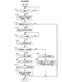
図5は、テレビジョン受像機100で行う異常復帰処理の手順を示すフローチャートである。各処理は制御部1が実行する。先ず制御部1は、テレビジョン受像機100のメイン電源をONする時に(ステップS11:YES)、記憶部16にて前回終了時(メイン電源のOFF時)の各部の状態記録D2を検索する(ステップS12)。メイン電源をONすることで、各部への電源供給がON(開始)されて、テレビジョン受像機100が起動状態になる。ステップS11のメイン電源のONは、ユーザによりメイン電源スイッチがON操作されたときまたはタイマがメイン電源ON時間になったときに制御部1が行う。制御部1は、前回終了時に記憶部16に状態記録D2を記録しなかったため、該状態記録D2を記憶部16から見つけられず読み込むことができなければ(ステップS13:NO)、処理を終了する。一方、制御部1は、前回終了時に記憶部16に状態記録D2を記録したため、該状態記録D2を記憶部16から見つけて読み込むことができれば(ステップS13:YES)、該状態記録D2が示す前回の各部の状態を継続する(ステップS14)。具体的には、制御部1は、前回の作動中にICカード10の温度異常とファン20の故障を検出して、ICカード10への供給電圧をOFFし、ファン20の故障および交換とICカード10の抜き取りとを通知し、ケーブルテレビ放送視聴モードへの切り替えを禁止したことを状態記録D2から認識し、例えばICカード10への供給電圧をOFF状態のままにし、ケーブルテレビ放送視聴モードへの切り替えを禁止状態のままにする。
FIG. 5 is a flowchart showing the procedure of the abnormal recovery process performed by the
そして、制御部1は、カードスロット9にICカード10が装着されていることを検出すると(ステップS15:YES)、ファン20への供給電圧をONして(ステップS16)、ファン20の回転数を周期的に検出する。しばらくしてファン20の回転数が供給電圧のレベルに対応する一定の回転数以上にならなければ(ステップS17:NO)、制御部1は、ファン20が交換されておらず異常動作中であると判断する(ステップS18)。そして、制御部1は、ファン20が故障したためICカード10の抜き取りとファン20の交換とを促すことと、ケーブルテレビ放送視聴モードで使用できないこととを、表示部14へのメッセージの表示により通知して(ステップS19)、処理を終了する。図6は、このときの表示部14の表示画面の一例を示す図である。表示部14の画面G3中には、ファン20の故障を示すメッセージM4、ICカード10の抜き取りを促すメッセージM5、ファン20の交換を促すメッセージM6、および現在ケーブルテレビ放送視聴モードでの使用が不可能なことを示すメッセージM7がそれぞれ表示されている。画面G3中のメッセージM4〜M7以外の部分には、地上波放送視聴モードまたは外部入力視聴モードで取得した映像等が表示される。メッセージM4〜M7は一定時間表示される。
When the
一方、ファン20への供給電圧をONした後、しばらくしてファン20の回転数が一定の回転数以上になれば(図5のステップS17:YES)、制御部1は、ファン20が交換されて正常動作中であると判断する(ステップS20)。そして、制御部1は、ICカード10への供給電圧をONして(ステップS21)、ケーブルテレビ放送視聴モードへの切り替えを許可する(ステップS22)。具体的には、ケーブルテレビ放送視聴モードの禁止フラグをOFFし、操作部17が操作されて、ケーブルテレビ放送のチャンネルが選局されたときに、該チャンネルの映像と音声を出力するための動作を各部に行わせて、該映像と音声を視聴できるようにする。そして、制御部1は、記憶部16から前回終了時の状態記録D2を消去して(ステップS23)、処理を終了する。
On the other hand, after the supply voltage to the
以上の実施形態によると、テレビジョン受像機100において、ICカード10の温度と温度センサ18の計測温度との相関情報D1と、温度センサ18の計測温度とに基づいて、カードスロット9に装着されたICカード10の正確な温度を検出することができる。このため、ICカード10の温度が許容温度を上回ったときに、ケーブルテレビ放送視聴モードから地上波放送視聴モードまたは外部入力視聴モードへ切り替えたり、ICカード10への供給電圧をOFFしたり、ケーブルテレビ放送視聴モードへの切り替えを禁止したりして、ICカード10の動作を停止して発熱を抑制するように適切に対処することができる。よって、ファン20が故障して正常に動作しなくなっても、ICカード10が熱により故障するのを防止することが可能となる。
According to the above embodiment, in the
また、前述した特許文献1、2では、ファン20が故障したり、内部温度がある温度を越えたりすると、各部への電源の供給を停止するので、テレビジョン受信機が使用できなくなる。然るに、以上の実施形態によると、ICカード10の動作を停止して、ケーブルテレビ放送視聴モードでの使用のみを禁止するので、ファン20が故障したり、ICカード10の温度が許容温度を上回ったりしても、ICカード10を保護しつつ、テレビジョン受像機100を地上波放送視聴モードまたは外部入力視聴モードで使用して、該映像と音声を視聴して楽しむことが可能となる。
Further, in
また、ファン20の故障を通知してICカード10の抜き取りとファン20の交換を促すメッセージM4〜M6を表示部14に表示させるので、ユーザに即座にファン20の故障を気付かせて、ICカード10の抜き取りとファン20の交換を行わせることができる。また、メイン電源をONした後、故障中のファン20が交換されていない場合に、メッセージM4〜M6と、ケーブルテレビ放送視聴モードで使用できないことを示すメッセージM7とを表示部14に表示させるので、ユーザが忘れていたり、ユーザが入れ代わったりしても、ユーザにファン20が故障していることとケーブルテレビ放送視聴モードで使用できないこととを再度通知して、ICカード10の抜き取りとファン20の交換を即座に行わせることができる。よって、ICカード10が熱により故障するのを一層防止することが可能となる。また、異常が発生したため視聴モードを強制的に切り替えることを示すメッセージM1〜M3を表示部14に表示させるので、ユーザが突然の視聴モードの変更で不安になるのを緩和することができる。
Further, since messages M4 to M6 that notify the failure of the
また、ICカード10の温度が許容温度を上回ったときの各部の状態を、次回メイン電源をONして起動したときに継続するので、ファン20が故障している間は何度起動しても、ICカード10への供給電圧をONせず、ケーブルテレビ放送視聴モードへの切り替えを禁止することができる。よって、ICカード10の動作が開始されず発熱が抑制され、ICカード10が熱により故障するのを一層防止することが可能となる。
In addition, since the state of each part when the temperature of the
さらに、メイン電源のON時にファン20が正常なものに交換されたことを検出し、即座にICカード10を動作させて、前回終了時の状態記録D2を消去するので、テレビジョン受像機100をケーブルテレビ放送視聴モードでも使用可能に復帰させることができる。このため、以降はケーブルテレビ放送と地上波放送と外部入力のそれぞれの映像と音声を視聴して楽しむことが可能となる。
Further, when the main power supply is turned on, it is detected that the
本発明は、以上の実施形態以外にも種々の形態を採用することができる。例えば、以上の実施形態では、デジタルケーブルテレビ放送信号、地上波放送信号、および外部入力信号を受信するテレビジョン受像機100に本発明を適用した例を挙げたが、本発明は、例えばデジタルまたはアナログのケーブルテレビ放送信号、地上波放送信号、衛星放送信号、および外部入力信号の少なくとも2つ以上を受信し、そのうちスクランブルされた受信信号を装着されたICカードによりデスクランブルするテレビジョン受像機、光ディスクレコーダやハードディスクレコーダといった映像機器、またはSTB等のテレビジョン受信機にも適用することが可能である。
The present invention can adopt various forms other than the above embodiment. For example, in the above embodiment, the example in which the present invention is applied to the
図7および図8は、他の実施形態を示す図である。図中、図1と同一部分には同一符号を付してある。図8に示すテレビジョン受信機102は、映像を表示する表示手段と、音声を出力する音声出力手段とを備えていない、光ディスクレコーダやハードディスクレコーダ等の映像機器またはSTB等から成る。光ディスクドライブやハードディスクドライブ等の記録装置は図示を省略している。図7に示すテレビジョン受像機101と図8のテレビジョン受信機102では、デジタルまたはアナログのケーブルテレビ放送信号、地上波放送信号、または衛星放送信号が入力端子4から入力される。これらの放送信号のうち、有料チャンネルの放送信号はスクランブルされていて、無料チャンネルの放送信号はスクランブルされていない。また、入力端子3から入力される外部入力信号もスクランブルされていない。チューナ部5aは、上記放送信号を受信可能なアナログ/デジタル対応チューナから成る。チューナ部5aは、入力端子4を介して受信した放送信号より、選局されたチャンネルの周波数の信号を抽出する。そして、チューナ部5aは、そのうちデジタルの放送信号をMPEG処理部6aへ入力し、アナログの放送信号を映像音声信号に変換して、A/V_SW12aへ入力する。
7 and 8 are diagrams showing another embodiment. In the figure, the same parts as those in FIG. The
MPEG処理部6aは、デジタルの放送信号のうち、スクランブルされた放送信号をデモジュレータ7からICカード10を経由してデコーダ8へ入力し、スクランブルされていない放送信号をデモジュレータ7からデコーダ8へ入力する。ケーブルテレビ放送信号、地上波放送信号、または衛星放送信号のうち、スクランブルされた信号はICカード10のデスクランブラ11aでデスクランブルされる。制御部1aは、A/V処理部13(図7)またはA/V処理部13a(図8)へ入力する映像音声信号を、A/V_SW12aでMPEG処理部6からの入力信号、チューナ部5aからの入力信号、または入力端子3からの外部入力信号のいずれかに切り替える。図7のA/V処理部13は、入力されたデジタルまたはアナログの映像音声信号のうち、映像信号を表示部14に出力し、音声信号を音声出力部15へ出力する。図8のA/V処理部13aは、入力されたデジタルまたはアナログの映像音声信号に対して、アナログ変換またはデジタル変換等の処理を施して、図示しない外部のテレビジョン受像機等へ出力端子23から出力したり、内蔵する記録装置へ出力したりする。
The
図9は、テレビジョン受像機101またはテレビジョン受信機102で行う異常検出対応処理の手順を示すフローチャートである。図2と同一処理には同一符号を付してある。各処理は制御部1aが実行する。ケーブルテレビ放送信号、地上波放送信号、衛星放送信号、または外部入力信号のいずれかを受信して、該受信信号に基づく映像音声信号を、A/V処理部13、13aから出力する通常の映像音声出力動作中に(ステップS0a)、ICカード10の温度が許容温度を上回ると(ステップS1:YES)、制御部1aはファン20が故障したと判断する(ステップS2)。そして、制御部1aは、このときICカード10のデスクランブラ11aでデスクランブルする可能性がある受信信号に基づく映像音声信号を出力する有料出力モード中であれば(ステップS3a:YES)、デスクランブラ11aでデスクランブルする可能性がない受信信号に基づく映像音声信号を出力する無料出力モードへ切り替える(ステップS4a)。上記において、デスクランブラ11aでデスクランブルする可能性がある受信信号とは、実際にスクランブルされていて、ICカード10へ入力させることが定められている有料の放送チャンネルの放送信号のことである。受信信号が有料の放送チャンネルの放送信号であるか否かは、選局されている放送チャンネルが有料チャンネルか無料チャンネルかを確認することで判断できる。放送チャンネルの有料・無料の情報は、記憶部16に予め記憶されている。デスクランブラ11aでデスクランブルする可能性がない受信信号とは、実際にスクランブルされておらず、ICカード10へ入力させることが定められていない無料の放送チャンネルの放送信号と外部入力信号のことである。
FIG. 9 is a flowchart showing a procedure of abnormality detection handling processing performed by the
また、制御部1aは、異常が発生したため出力モードを切り替えることを通知する(ステップS5a)。テレビジョン受信機102の場合、例えば通知したい内容を示すメッセージ等を、接続されたテレビジョン受像機の表示部にオンスクリーン表示させる。一方、ステップS3aで有料出力モード中でなければ(ステップS3a:NO)、制御部1aは、現在の無料出力モードを継続する。そして、制御部1aは、ICカード10への供給電圧をOFFし(ステップS6)、ファン20が故障したためカードスロット9からのICカード10の抜き取りとファン20の交換とを促す通知を行う(ステップS7a)。このとき、ファン20の交換等を促すことで、ユーザにファン20の故障を察知させることができるので、ファン20の故障の通知は省略してもよい。そして、制御部1aは、以降の有料出力モードへの切り替えを禁止し(ステップS8a)、メイン電源をOFFする時に(ステップS9:YES)、各部の状態を記憶部16に記録して(ステップS10a、図7および図8の状態記録D3)、処理を終了する。ステップS10aで作成される状態記録D3の内容としては、例えばICカード10の温度異常が発生したこと、ファン20が故障したこと、ICカード10への供給電圧をOFFしたこと、ファン20の故障および交換とICカード10の抜き取りとを通知したこと、並びに有料出力モードへの切り替えを禁止したことがある。
In addition, the control unit 1a notifies that the output mode is switched because an abnormality has occurred (step S5a). In the case of the
図10は、テレビジョン受像機101またはテレビジョン受信機102で行う異常復帰処理の手順を示すフローチャートである。図5と同一処理には同一符号を付してある。各処理は制御部1aが実行する。先ず制御部1aは、メイン電源をONする時に(ステップS11:YES)、記憶部16にて前回の各部の状態記録D3を検索し(ステップS12a)、該状態記録D3を読み込むことができれば(ステップS13a:YES)、該状態記録D3が示す前回終了時の各部の状態を継続する(ステップS14a)。具体的には、制御部1aは、前回の作動中にICカード10の温度異常とファン20の故障を検出して、ICカード10への供給電圧をOFFし、ファン20の故障および交換とICカード10の抜き取りとを通知し、有料出力モードへの切り替えを禁止したことを状態記録D3から認識し、例えばICカード10への供給電圧をOFF状態のままにし、有料出力モードへの切り替えを禁止状態のままにする。そして、制御部1aは、ICカード10の装着を検出すると(ステップS15:YES)、ファン20への供給電圧をONする(ステップS16)。
FIG. 10 is a flowchart showing the procedure of the error recovery process performed by the
しばらくしてファン20の回転数が一定の回転数以上にならなければ(ステップS17:NO)、制御部1aは、ファン20が交換されておらず異常動作中であると判断し(ステップS18)、ファン20が故障したためICカード10の抜き取りとファン20の交換とを促し、かつ有料出力モードで使用できないことを通知して(ステップS19a)、処理を終了する。一方、しばらくしてファン20の回転数が一定の回転数以上になれば(ステップS17:YES)、制御部1aは、ファン20が交換されて正常動作中であると判断し(ステップS20)、ICカード10への供給電圧をONして(ステップS21)、有料出力モードへの切り替えを許可する(ステップS22a)。そして、制御部1aは、記憶部16から前回終了時の状態記録D3を消去して(ステップS23a)、処理を終了する。
If the rotational speed of the
以上の他の実施形態によると、テレビジョン受像機101およびテレビジョン受信機102において、相関情報D1と温度センサ18の計測温度とに基づいて、カードスロット9に装着されたICカード10の正確な温度を検出することができる。このため、ICカード10の温度が許容温度を上回ったときに、有料出力モードから無料出力モードへ切り替えたり、ICカード10への供給電圧をOFFしたり、有料出力モードへの切り替えを禁止したりして、ICカード10の動作を停止して発熱を抑制するように、適切に対処することができる。よって、ファン20が故障して正常に動作しなくなっても、ICカード10が熱により故障するのを防止することが可能となる。また、ファン20が故障したり、ICカード10の温度が許容温度を上回ったりしても、ICカード10を保護しつつ、テレビジョン受像機101およびテレビジョン受信機102を無料出力モードで使用することが可能となる。
According to the other embodiment described above, in the
また、ファン20の故障を通知したり、ICカード10の抜き取りとファン20の交換を促すように通知したり、有料出力モードで使用できないことを通知したりするので、ユーザに即座にファン20の故障と有料出力モードでの使用不可を気付かせて、ICカード10の抜き取りとファン20の交換を行わせることができ、ICカード10が熱により故障するのを一層防止することが可能となる。また、異常が発生したため出力モードを強制的に切り替えることを通知するので、ユーザが突然の視聴モードの変更で不安になるのを緩和することができる。また、ICカード10の温度が許容温度を上回ったときの各部の状態を、次回の起動時に継続するので、ファン20が故障している間は何度起動しても、ICカード10への供給電圧がONされず、有料出力モードへの切り替えが禁止され、ICカード10の動作が開始されず発熱が抑制され、ICカード10が熱により故障するのを一層防止することが可能となる。さらに、メイン電源のON時にファン20が正常なものに交換されたことを検出し、即座にICカード10を動作させて、前回終了時の状態記録D3を消去するので、テレビジョン受像機101およびテレビジョン受信機102を有料出力モードでも使用可能に復帰させることが可能となる。
In addition, the failure of the
1、1a 制御部
1b、1e GPIO
9 カードスロット
10 ICカード
11、11a デスクランブラ
14 表示部
15 音声出力部
16 記憶部
18 温度センサ
20 ファン
100、101 テレビジョン受像機
102 テレビジョン受信機
D1 相関情報
D2、D3 状態記録
1,
9
Claims (5)
前記記憶手段には、前記カードスロットに装着された前記ICカードの温度と前記温度センサの計測温度との相関を示す情報が予め記憶されていて、
前記制御手段は、前記ファンを回転させて前記ICカードを冷却し、
前記記憶手段の前記相関情報と前記温度センサの計測温度とに基づいて前記ICカードの温度を検出し、
前記ICカードの温度が許容温度を上回ったときに、前記ファンが故障したと判断し、前記ICカードの前記デスクランブラでデスクランブルする可能性がある前記ケーブルテレビ放送信号に基づく映像を前記表示手段に表示しかつ音声を前記音声出力手段から出力する一方のモード中であれば、前記ICカードの前記デスクランブラでデスクランブルする可能性がない前記地上波放送信号または前記外部入力信号に基づく映像を前記表示手段に表示しかつ音声を前記音声出力手段から出力する他方のモードへ切り替え、前記ICカードへの供給電圧をオフし、前記ファンの故障を通知して前記ICカードの抜き取りと前記ファンの交換を促す表示を前記表示手段に表示し、前記一方のモードへの切り替えを禁止し、この後のメイン電源のオフ時に、各部の状態を前記記憶手段に記録し、
メイン電源のオン時に、前記記憶手段から前回のメイン電源のオフ時の前記各部の状態の記録を読み込んで、該状態を継続し、前記装着検出手段により前記ICカードの装着を検出すると、前記ファンへの供給電圧をオンし、前記回転数検出手段により前記ファンの回転数が一定の回転数以上になったことを検出すると、前記ファンが交換されて正常動作中であると判断して、前記ICカードへの供給電圧をオンし、前記一方のモードへの切り替えを許可し、前記記憶手段から前記各部の状態の記録を消去することを特徴とするテレビジョン受像機。 A card slot in which an IC card having a descrambler that descrambles a scrambled signal is detachable, a mounting detection means for detecting the mounting of the IC card in the card slot, a fan, and a rotation speed of the fan A rotation speed detection means for detecting, a temperature sensor, a display means, an audio output means, a storage means, and a control means for controlling the operation of each part, and includes a cable TV broadcast signal, a terrestrial broadcast signal, or an external Receives an input signal from a video device, acquires a video signal and an audio signal from the signal, outputs the video signal to a display unit to display a video, outputs the audio signal to an audio output unit, and outputs an audio signal In a television receiver that outputs
The storage means stores in advance information indicating the correlation between the temperature of the IC card mounted in the card slot and the measured temperature of the temperature sensor,
The control means rotates the fan to cool the IC card,
Detecting the temperature of the IC card based on the correlation information of the storage means and the measured temperature of the temperature sensor;
When the temperature of the IC card exceeds an allowable temperature, it is determined that the fan has failed, and an image based on the cable television broadcast signal that may be descrambled by the descrambler of the IC card is displayed on the display unit. And the video based on the terrestrial broadcast signal or the external input signal that is not likely to be descrambled by the descrambler of the IC card. Switching to the other mode of displaying on the display means and outputting sound from the sound output means, turning off the supply voltage to the IC card, notifying the fan failure and removing the IC card and the fan A display prompting replacement is displayed on the display means, switching to the one mode is prohibited, and the main power supply is switched on after this. Sometimes, to record each part of the state in the storage means,
When the main power is turned on, a record of the state of each part when the main power was last turned off is read from the storage means, the state is continued, and when the mounting detection means detects the mounting of the IC card, the fan When the supply voltage to is turned on and the rotation speed detection means detects that the rotation speed of the fan has reached a certain rotation speed or more, it is determined that the fan has been replaced and is operating normally, A television receiver characterized in that the supply voltage to the IC card is turned on, the switching to the one mode is permitted, and the record of the state of each part is erased from the storage means.
前記記憶手段には、前記カードスロットに装着された前記ICカードの温度と前記温度センサの計測温度との相関を示す情報が予め記憶されていて、
前記制御手段は、前記ファンを回転させて前記ICカードを冷却し、
前記記憶手段の前記相関情報と前記温度センサの計測温度とに基づいて前記ICカードの温度を検出し、
前記ICカードの温度が許容温度を上回ったときに、前記ファンが故障したと判断し、前記ICカードの前記デスクランブラでデスクランブルする可能性がある受信信号に基づく映像音声信号を出力する一方のモード中であれば、前記ICカードの前記デスクランブラでデスクランブルする可能性がない受信信号に基づく映像音声信号を出力する他方のモードへ切り替え、前記ICカードへの供給電圧をオフし、前記一方のモードへの切り替えを禁止することを特徴とするテレビジョン受信機。 A television receiver comprising a card slot in which an IC card having a descrambler for descrambling a scrambled signal is detachable, a fan, a temperature sensor, storage means, and control means for controlling the operation of each part. In
The storage means stores in advance information indicating the correlation between the temperature of the IC card mounted in the card slot and the measured temperature of the temperature sensor,
The control means rotates the fan to cool the IC card,
Detecting the temperature of the IC card based on the correlation information of the storage means and the measured temperature of the temperature sensor;
When the temperature of the IC card exceeds an allowable temperature, it is determined that the fan has failed, and one of the video and audio signals based on a received signal that may be descrambled by the descrambler of the IC card is output. If in mode, switch to the other mode that outputs video and audio signals based on received signals that are not likely to be descrambled by the descrambler of the IC card, turn off the supply voltage to the IC card A television receiver characterized by prohibiting switching to a mode.
前記制御手段は、前記ICカードの温度が許容温度を上回って、前記モードの切り替えと前記ICカードへの供給電圧のオフを行った後、前記ICカードの抜き取りと前記ファンの交換を促すような通知を行うことを特徴とするテレビジョン受信機。 The television receiver according to claim 2,
The control means prompts removal of the IC card and replacement of the fan after switching the mode and turning off the supply voltage to the IC card when the temperature of the IC card exceeds the allowable temperature. A television receiver for performing notification.
前記制御手段は、前記ICカードの温度が許容温度を上回った後のメイン電源のオフ時に、各部の状態を前記記憶手段に記録し、
メイン電源のオン時に、前記記憶手段から前回のメイン電源のオフ時の前記各部の状態の記録を読み込んで、該状態を継続することを特徴とするテレビジョン受信機。 The television receiver according to claim 2 or 3,
The control means records the state of each part in the storage means when the main power is turned off after the temperature of the IC card exceeds the allowable temperature.
A television receiver characterized in that when the main power is turned on, a record of the state of each unit when the main power was last turned off is read from the storage means and the state is continued.
前記カードスロットへの前記ICカードの装着を検出する装着検出手段と、
前記ファンの回転数を検出する回転数検出手段と、を備え、
前記制御手段は、メイン電源のオン時に、前記カードスロットに前記ICカードが装着されていれば、前記ファンへの供給電圧をオンし、前記ファンの回転数が一定の回転数以上になれば、前記ファンが交換されて正常動作中であると判断して、前記ICカードへの供給電圧をオンし、前記一方のモードへの切り替えを許可することを特徴とするテレビジョン受信機。 The television receiver according to any one of claims 2 to 4,
Mounting detection means for detecting mounting of the IC card in the card slot;
A rotational speed detection means for detecting the rotational speed of the fan,
The control means turns on the supply voltage to the fan if the IC card is inserted in the card slot when the main power is turned on, and if the rotational speed of the fan becomes a certain rotational speed or more, A television receiver characterized by judging that the fan is replaced and operating normally, turning on the supply voltage to the IC card and permitting switching to the one mode.
Priority Applications (2)
| Application Number | Priority Date | Filing Date | Title |
|---|---|---|---|
| JP2007057113A JP4798024B2 (en) | 2007-03-07 | 2007-03-07 | Television receiver, television receiver |
| US12/043,333 US7788545B2 (en) | 2007-03-07 | 2008-03-06 | Broadcast receiving device |
Applications Claiming Priority (1)
| Application Number | Priority Date | Filing Date | Title |
|---|---|---|---|
| JP2007057113A JP4798024B2 (en) | 2007-03-07 | 2007-03-07 | Television receiver, television receiver |
Publications (2)
| Publication Number | Publication Date |
|---|---|
| JP2008219731A JP2008219731A (en) | 2008-09-18 |
| JP4798024B2 true JP4798024B2 (en) | 2011-10-19 |
Family
ID=39839190
Family Applications (1)
| Application Number | Title | Priority Date | Filing Date |
|---|---|---|---|
| JP2007057113A Expired - Fee Related JP4798024B2 (en) | 2007-03-07 | 2007-03-07 | Television receiver, television receiver |
Country Status (2)
| Country | Link |
|---|---|
| US (1) | US7788545B2 (en) |
| JP (1) | JP4798024B2 (en) |
Families Citing this family (11)
| Publication number | Priority date | Publication date | Assignee | Title |
|---|---|---|---|---|
| US8001418B2 (en) * | 2008-03-07 | 2011-08-16 | Ek3 Technologies, Inc. | Fault detection and correction for single and multiple media players connected to electronic displays, and related devices, methods and systems |
| US9423846B2 (en) * | 2008-04-10 | 2016-08-23 | Nvidia Corporation | Powered ring to maintain IO state independent of the core of an integrated circuit device |
| US8762759B2 (en) | 2008-04-10 | 2014-06-24 | Nvidia Corporation | Responding to interrupts while in a reduced power state |
| WO2009128839A1 (en) * | 2008-04-19 | 2009-10-22 | Hewlett-Packard Development Company, L.P. | Device and method for cooling fan control using measured amperage load |
| US8464300B2 (en) * | 2008-09-16 | 2013-06-11 | Dish Network L.L.C. | Systems and methods for receiving device health management |
| CN101924955A (en) * | 2009-06-16 | 2010-12-22 | 中兴通讯股份有限公司 | A method and system for improving the broadcasting quality of mobile phone TV |
| FR2968870A1 (en) * | 2010-12-10 | 2012-06-15 | France Telecom | METHOD FOR COLLECTING AND PROCESSING INFORMATION REPRESENTATIVE OF CONDITIONS FOR OPERATING AN EQUIPMENT |
| KR20140053531A (en) * | 2012-10-26 | 2014-05-08 | 삼성전자주식회사 | Broadcasting signal receiving apparatus and control method thereof |
| CN103094793B (en) | 2013-01-07 | 2015-11-25 | 华为终端有限公司 | The smart card connecting circuit of electronic equipment and electronic equipment |
| CN103997682A (en) * | 2014-05-13 | 2014-08-20 | 深圳市九洲电器有限公司 | Temperature control method and system of set top box |
| CN116050276A (en) * | 2023-02-14 | 2023-05-02 | 广东电网有限责任公司 | Cable Core Temperature Prediction Method and System Based on VMD-LSSVM |
Family Cites Families (11)
| Publication number | Priority date | Publication date | Assignee | Title |
|---|---|---|---|---|
| US5675390A (en) * | 1995-07-17 | 1997-10-07 | Gateway 2000, Inc. | Home entertainment system combining complex processor capability with a high quality display |
| KR19990037403A (en) * | 1997-10-27 | 1999-05-25 | 이데이 노부유끼 | Digital broadcasting receiver |
| JPH11355751A (en) * | 1998-06-03 | 1999-12-24 | Toshiba Corp | Digital broadcast receiving apparatus and control method thereof |
| US6325636B1 (en) * | 2000-07-20 | 2001-12-04 | Rlx Technologies, Inc. | Passive midplane for coupling web server processing cards with a network interface(s) |
| JP4598980B2 (en) * | 2001-03-29 | 2010-12-15 | マスプロ電工株式会社 | CATV amplifier |
| JP3548166B2 (en) * | 2002-05-10 | 2004-07-28 | 株式会社シーテック | Head amplifier monitoring device of CATV system and CATV system |
| US7353321B2 (en) * | 2003-01-13 | 2008-04-01 | Sierra Logic | Integrated-circuit implementation of a storage-shelf router and a path controller card for combined use in high-availability mass-storage-device shelves that may be incorporated within disk arrays |
| US7502369B2 (en) * | 2004-06-02 | 2009-03-10 | Intel Corporation | High speed interface systems and methods |
| JP2006080600A (en) * | 2004-09-07 | 2006-03-23 | Pioneer Electronic Corp | Catv terminal device and maintenance control method thereof |
| JP4166221B2 (en) * | 2005-01-07 | 2008-10-15 | 三洋電機株式会社 | In-vehicle digital broadcast receiver |
| US20070143801A1 (en) * | 2005-12-20 | 2007-06-21 | Madonna Robert P | System and method for a programmable multimedia controller |
-
2007
- 2007-03-07 JP JP2007057113A patent/JP4798024B2/en not_active Expired - Fee Related
-
2008
- 2008-03-06 US US12/043,333 patent/US7788545B2/en not_active Expired - Fee Related
Also Published As
| Publication number | Publication date |
|---|---|
| US7788545B2 (en) | 2010-08-31 |
| JP2008219731A (en) | 2008-09-18 |
| US20090070621A1 (en) | 2009-03-12 |
Similar Documents
| Publication | Publication Date | Title |
|---|---|---|
| JP4798024B2 (en) | Television receiver, television receiver | |
| JP2007060223A (en) | Television receiver having multiple standby power modes | |
| US20100269129A1 (en) | Broadcasting processing apparatus and control method of the same | |
| JP3769236B2 (en) | Digital information recording / playback system | |
| EP1631085A1 (en) | Broadcasting receiving apparatus, broadcasting receiving method, and broadcasting receiving system | |
| US20060095935A1 (en) | Method for receiving digital broadcast signal | |
| CN100505857C (en) | Information processing apparatus | |
| JP5040502B2 (en) | Broadcast receiving apparatus, method and program | |
| EP1734751A2 (en) | Apparatuses, methods, and data structures for hard reset | |
| US20060280440A1 (en) | Receiver, program recording controller, program recording control method and program recording system | |
| JP2006211604A (en) | Television receiver | |
| US20100079679A1 (en) | System and method of power management in conditional access based receivers | |
| EP1650970A1 (en) | Apparatus and method for controlling recording operation | |
| JP2002252817A (en) | Digital broadcast receiver | |
| JP2011003962A (en) | Video voice decoder and video voice decoding method | |
| JP2007288476A (en) | DIGITAL BROADCAST RECEIVING SYSTEM, DIGITAL BROADCAST RECEIVING DEVICE, LIMITED RECEPTION PROCESSING DEVICE, DIGITAL BROADCAST RECEIVING METHOD, AND DIGITAL BROADCAST RECEIVING PROGRAM | |
| JP2004187038A (en) | Video display device | |
| JP2008311751A (en) | Broadcast receiver | |
| JP3726514B2 (en) | Magnetic recording / reproducing device | |
| JP2008311710A (en) | Broadcast receiver | |
| KR100655550B1 (en) | Power saving device and method in standby mode of digital TV with digital cable ready function | |
| JP5173661B2 (en) | Recording apparatus and control method thereof | |
| JP2008109388A (en) | Broadcasting receiving and recording apparatus | |
| KR20060114192A (en) | Broadcast signal reproduction method of digital broadcast receiving system | |
| US8472780B2 (en) | Television and method for controlling the same |
Legal Events
| Date | Code | Title | Description |
|---|---|---|---|
| A621 | Written request for application examination |
Free format text: JAPANESE INTERMEDIATE CODE: A621 Effective date: 20090924 |
|
| TRDD | Decision of grant or rejection written | ||
| A01 | Written decision to grant a patent or to grant a registration (utility model) |
Free format text: JAPANESE INTERMEDIATE CODE: A01 Effective date: 20110705 |
|
| A01 | Written decision to grant a patent or to grant a registration (utility model) |
Free format text: JAPANESE INTERMEDIATE CODE: A01 |
|
| A61 | First payment of annual fees (during grant procedure) |
Free format text: JAPANESE INTERMEDIATE CODE: A61 Effective date: 20110718 |
|
| FPAY | Renewal fee payment (event date is renewal date of database) |
Free format text: PAYMENT UNTIL: 20140812 Year of fee payment: 3 |
|
| R150 | Certificate of patent or registration of utility model |
Free format text: JAPANESE INTERMEDIATE CODE: R150 |
|
| LAPS | Cancellation because of no payment of annual fees |