JP4822832B2 - 測定装置及び測定方法 - Google Patents
測定装置及び測定方法 Download PDFInfo
- Publication number
- JP4822832B2 JP4822832B2 JP2005364180A JP2005364180A JP4822832B2 JP 4822832 B2 JP4822832 B2 JP 4822832B2 JP 2005364180 A JP2005364180 A JP 2005364180A JP 2005364180 A JP2005364180 A JP 2005364180A JP 4822832 B2 JP4822832 B2 JP 4822832B2
- Authority
- JP
- Japan
- Prior art keywords
- plate
- movement
- moving object
- indicator plate
- reading
- Prior art date
- Legal status (The legal status is an assumption and is not a legal conclusion. Google has not performed a legal analysis and makes no representation as to the accuracy of the status listed.)
- Expired - Fee Related
Links
- 238000000034 method Methods 0.000 title description 4
- 238000000691 measurement method Methods 0.000 claims description 5
- 239000003086 colorant Substances 0.000 claims description 3
- 238000005259 measurement Methods 0.000 description 15
- 230000000007 visual effect Effects 0.000 description 3
- 238000005530 etching Methods 0.000 description 1
- 238000009434 installation Methods 0.000 description 1
- 238000004519 manufacturing process Methods 0.000 description 1
- 239000002184 metal Substances 0.000 description 1
- 238000010422 painting Methods 0.000 description 1
- 238000007639 printing Methods 0.000 description 1
Images


Landscapes
- A Measuring Device Byusing Mechanical Method (AREA)
Description
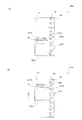
図1は、本発明の実施形態1に係る測定装置の斜視図であり、図2は、測定装置の側面図であり、図3は、測定装置の正面図である。
図4は、本発明の実施形態2に係る測定装置の正面図である。なお、上述した実施形態1と同様の部材には同一の符号を付して重複する説明は省略する。
以上、本発明の各実施形態を説明したが、本発明の基本的構成は上述したものに限定されるものではない。例えば、上述した実施形態1及び2の指示板20の表面と裏面とを異なる色で形成するようにしてもよい。これにより、読取板30の鏡面31中には、指示板20、20Aの裏面が鏡像120、120Aとして写るため、測定者2が直接目視する指示板20、20Aの表面と、読取板30の鏡面31中の指示板20、20Aの鏡像120、120Aとが異なる色となり、直線部21と鏡像120、120AのV字部122、122Aの点123、123Aとの位置決めをさらに容易に行うことができる。なお、指示板20、20Aの表面と裏面とを異なる色で形成する場合、表面と裏面とのコントラスト比が高くなるように着色するのが好ましい。
Claims (5)
- 縁部の少なくとも一部に直線部が形成されていると共に、前記縁部に前記直線部に接し且つ当該直線部の直線方向に交差する2辺で構成されたV字部が形成された指示板と、一方面に鏡及び目盛りが設けられた読取板とを具備し、
前記指示板及び前記読取板の何れか一方を固定位置に取り付けると共に、他方を移動量を測定する移動対象に取り付けて、目視位置に近い方から前記指示板、前記読取板と直線状に並べ、前記指示板の前記直線部と前記鏡中の指示板の鏡像の前記V字部の前記2辺が交差する点とを一致させた状態で前記直線部が指示する目盛りを読み取ることを特徴とする測定装置。 - 前記指示板の表面と裏面とが異なる色で形成されていることを特徴とする請求項1記載の測定装置。
- 前記指示板及び前記読取板の何れか一方の前記移動対象への固定が、磁石により行われることを特徴とする請求項1又は2に記載の測定装置。
- 前記指示板の前記直線部が、面方向の一方向の少なくとも一端部側に設けられていると共に、前記V字部が前記一方向に交差する方向の一端部側に設けられていることを特徴とする請求項1〜3の何れかに記載の測定装置。
- 移動対象の移動量を測定する測定方法において、
縁部の少なくとも一部に直線部が形成されていると共に、前記縁部に前記直線部に接し且つ当該直線部の直線方向に交差する2辺で構成されたV字部が形成された指示板と、一方面に鏡及び目盛りが設けられた読取板との何れか一方を固定位置に取り付けると共に、他方を移動量を測定する移動対象に取り付けて、目視位置に近い方から前記指示板、前記読取板と直線状に並べ、前記指示板の前記直線部と前記鏡中の指示板の鏡像の前記V字部の前記2辺が交差する点とを一致させた状態で前記直線部が指し示す前記目盛りを読み取った後、前記移動対象が移動後に前記指示板の前記直線部と前記鏡中の指示板の鏡像の前記V字部の前記2辺が交差する点とを一致させた状態で前記直線部が指し示す前記目盛りを読み取り、前記移動対象の移動前と移動後の読み取った前記目盛りから移動量を算出することを特徴とする測定方法。
Priority Applications (1)
| Application Number | Priority Date | Filing Date | Title |
|---|---|---|---|
| JP2005364180A JP4822832B2 (ja) | 2005-12-19 | 2005-12-19 | 測定装置及び測定方法 |
Applications Claiming Priority (1)
| Application Number | Priority Date | Filing Date | Title |
|---|---|---|---|
| JP2005364180A JP4822832B2 (ja) | 2005-12-19 | 2005-12-19 | 測定装置及び測定方法 |
Publications (2)
| Publication Number | Publication Date |
|---|---|
| JP2007170817A JP2007170817A (ja) | 2007-07-05 |
| JP4822832B2 true JP4822832B2 (ja) | 2011-11-24 |
Family
ID=38297589
Family Applications (1)
| Application Number | Title | Priority Date | Filing Date |
|---|---|---|---|
| JP2005364180A Expired - Fee Related JP4822832B2 (ja) | 2005-12-19 | 2005-12-19 | 測定装置及び測定方法 |
Country Status (1)
| Country | Link |
|---|---|
| JP (1) | JP4822832B2 (ja) |
Family Cites Families (5)
| Publication number | Priority date | Publication date | Assignee | Title |
|---|---|---|---|---|
| JPS58170502A (ja) * | 1982-03-31 | 1983-10-07 | Nitto Electric Ind Co Ltd | 膜汚染物除去方法 |
| JPS6474507A (en) * | 1987-09-16 | 1989-03-20 | Fujikura Ltd | Automatic supply device for coated optical fiber |
| IT1245008B (it) * | 1991-01-25 | 1994-09-13 | Lamsweerde Edoardo Van | Elemento graduato per lettura ottica a riflessione e procedimento per la sua fabbricazione |
| JPH11287604A (ja) * | 1998-04-05 | 1999-10-19 | Sachihiro Toshima | 構造物の出来形測定治具 |
| JP2005241248A (ja) * | 2004-01-30 | 2005-09-08 | Aronshiya:Kk | 光学式エンコーダに用いられる反射板及びその製造方法 |
-
2005
- 2005-12-19 JP JP2005364180A patent/JP4822832B2/ja not_active Expired - Fee Related
Also Published As
| Publication number | Publication date |
|---|---|
| JP2007170817A (ja) | 2007-07-05 |
Similar Documents
| Publication | Publication Date | Title |
|---|---|---|
| US4074131A (en) | Apparatus for measuring or setting two-dimensional position coordinates | |
| JPH0399213A (ja) | 長さ又は角度の測定装置 | |
| DE60204495D1 (de) | Linsenmesser zur Messung der Eigenschaft eines Brillenglases oder einer Kontaktlinse | |
| US8854616B2 (en) | Visual inspection apparatus for glass substrate of liquid crystal display and inspection method thereof | |
| CN104956176A (zh) | 用于测量角度的折尺和方法 | |
| US8898921B1 (en) | Multi-functional measuring tape | |
| JP2018179729A (ja) | 鉄筋ゲージ | |
| US20030126752A1 (en) | Right angle measuring design | |
| JP2007170817A (ja) | 測定装置及び測定方法 | |
| JP5595091B2 (ja) | クラックゲージ | |
| CN203011354U (zh) | 游标狭缝式光电自准直仪 | |
| JP3125109U (ja) | リングゲージ | |
| CN201322618Y (zh) | 一种定位尺标装置 | |
| US633263A (en) | Surveyor's instrument. | |
| US20080120852A1 (en) | Roof pitch gauge | |
| US20100141246A1 (en) | Magnetic Type Digital-analogic Position-sensing Device | |
| CN223636748U (zh) | 一种自动制孔设备制孔孔位精度检测装置 | |
| CN204788904U (zh) | 一种光轴偏移误差测定装置 | |
| KR20080000077U (ko) | 회전형 자를 구비한 각도기 | |
| KR20250146337A (ko) | 각도자 및 각도자 조립체 | |
| JP4054048B2 (ja) | 比率分割用目盛り | |
| KR101295693B1 (ko) | 갭 게이지 | |
| KR100547226B1 (ko) | 위치 보정이 가능한 변위측정 센서 | |
| FI60612B (fi) | Apparat foer uttagning av kurser i sjoekort e d | |
| JP2018072257A (ja) | 検査システム、及び画像処理装置、並びに検査システムの画像処理方法 |
Legal Events
| Date | Code | Title | Description |
|---|---|---|---|
| A621 | Written request for application examination |
Free format text: JAPANESE INTERMEDIATE CODE: A621 Effective date: 20081209 |
|
| A977 | Report on retrieval |
Free format text: JAPANESE INTERMEDIATE CODE: A971007 Effective date: 20110422 |
|
| A131 | Notification of reasons for refusal |
Free format text: JAPANESE INTERMEDIATE CODE: A131 Effective date: 20110601 |
|
| TRDD | Decision of grant or rejection written | ||
| A01 | Written decision to grant a patent or to grant a registration (utility model) |
Free format text: JAPANESE INTERMEDIATE CODE: A01 Effective date: 20110831 |
|
| A01 | Written decision to grant a patent or to grant a registration (utility model) |
Free format text: JAPANESE INTERMEDIATE CODE: A01 |
|
| A61 | First payment of annual fees (during grant procedure) |
Free format text: JAPANESE INTERMEDIATE CODE: A61 Effective date: 20110906 |
|
| R150 | Certificate of patent or registration of utility model |
Ref document number: 4822832 Country of ref document: JP Free format text: JAPANESE INTERMEDIATE CODE: R150 Free format text: JAPANESE INTERMEDIATE CODE: R150 |
|
| FPAY | Renewal fee payment (event date is renewal date of database) |
Free format text: PAYMENT UNTIL: 20140916 Year of fee payment: 3 |
|
| FPAY | Renewal fee payment (event date is renewal date of database) |
Free format text: PAYMENT UNTIL: 20140916 Year of fee payment: 3 |
|
| R250 | Receipt of annual fees |
Free format text: JAPANESE INTERMEDIATE CODE: R250 |
|
| R250 | Receipt of annual fees |
Free format text: JAPANESE INTERMEDIATE CODE: R250 |
|
| R250 | Receipt of annual fees |
Free format text: JAPANESE INTERMEDIATE CODE: R250 |
|
| R250 | Receipt of annual fees |
Free format text: JAPANESE INTERMEDIATE CODE: R250 |
|
| LAPS | Cancellation because of no payment of annual fees |