JP4831460B2 - Electric snow melting device structure for slab turnout - Google Patents
Electric snow melting device structure for slab turnout Download PDFInfo
- Publication number
- JP4831460B2 JP4831460B2 JP2005052754A JP2005052754A JP4831460B2 JP 4831460 B2 JP4831460 B2 JP 4831460B2 JP 2005052754 A JP2005052754 A JP 2005052754A JP 2005052754 A JP2005052754 A JP 2005052754A JP 4831460 B2 JP4831460 B2 JP 4831460B2
- Authority
- JP
- Japan
- Prior art keywords
- heater
- floor plate
- slab
- plate
- snow melting
- Prior art date
- Legal status (The legal status is an assumption and is not a legal conclusion. Google has not performed a legal analysis and makes no representation as to the accuracy of the status listed.)
- Expired - Lifetime
Links
Images






Landscapes
- Railway Tracks (AREA)
Description
本発明は、軌道スラブ上に設置されるレール分岐器を電気ヒータにより加熱して降雪時の積雪や凍結による作動不良を防止するための融雪装置構成体に関する。 The present invention relates to a snow melting apparatus structure for preventing malfunction due to snow accumulation or freezing during snowfall by heating a rail branching device installed on a track slab with an electric heater.
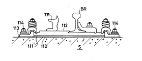
スラブ上に設置される分岐器は、図12に示されるように、スラブS上に硬質樹脂により成形された調整板110とゴムなどの弾性材により成形された軌道パッド111を重ねて配し、その上にレールを支持する床板112を載せ、この床板112の廻りに横圧受け金具113をアンカーボルト114で止めて固定し、床板112の上面に基本レールBRとトングレールTRを載せた構造となっている。
従来、このようなスラブ分岐器を加熱するための融雪装置として、分岐器の両側方に設置されて分岐器に温風を吹き付ける、電気温風式融雪装置が利用されていた(例えば特許文献1参照)。
As shown in FIG. 12, the branching device installed on the slab is arranged with the
Conventionally, as a snow melting device for heating such a slab branching device, an electric hot air type snow melting device that is installed on both sides of the branching device and blows warm air to the branching device has been used (for example, Patent Document 1). reference).
電気温風式融雪装置は、加熱対象である分岐器と熱源とが離れているため加熱効率が悪く、融雪に十分な温度まで分岐器を加熱するのに供給電力が過多となり、省電力化が図れないという問題があった。
分岐器を加熱する効率の点では、電気温風式融雪装置よりも、ヒータを分岐器に直に接続して熱を伝導させる構造の装置の方が優れ、省電力化も可能となる。しかし、スラブ分岐器では、第1に床板の下側に重ねられた調整板と軌道パッドの耐熱性が低く、分岐器をヒータで直に加熱した場合にヒータの熱によって調整板と軌道パッドがともに劣化し、軌道の不陸を生じさせて車両の乗り心地を悪化させるとともに他の軌道部品を劣化させる誘因となること、第2に床板を固定する横圧受け金具が床板の周囲に突出しているため、ヒータを取り付けるスペースがないことから、ヒータでスラブ分岐器を直に加熱する構造の融雪装置は使用されていないのが実状である。
The electric hot air type snow melting device has poor heating efficiency because the branching device to be heated and the heat source are separated from each other, and the supply power is excessive to heat the branching device to a temperature sufficient for melting snow, saving power. There was a problem that could not be planned.
In terms of the efficiency of heating the branching device, an apparatus having a structure in which a heater is directly connected to the branching device to conduct heat is superior to electric hot air type snow melting device, and power saving is also possible. However, in the slab branching device, first, the heat resistance of the adjustment plate and the track pad stacked on the lower side of the floor board is low, and when the branching device is directly heated by the heater, the adjustment plate and the track pad are heated by the heater. Both of them deteriorate and cause unevenness of the track, which deteriorates the ride comfort of the vehicle and deteriorates other track components. Secondly, the lateral pressure receiving metal fittings that fix the floor plate protrude around the floor plate. Therefore, since there is no space for attaching a heater, the actual situation is that a snow melting device having a structure in which the slab branching device is directly heated by the heater is not used.
本発明は従来技術の有するこのような問題点に鑑み、スラブ上に設置される分岐器に直に取り付けて加熱する融雪装置を構成し、スラブ上の分岐器を効率的に加熱して確実なレール切り替え動作を確保することを課題とする。 In view of such problems of the prior art, the present invention configures a snow melting device that is directly attached to a branching device installed on a slab and heats it, and heats the branching device on the slab efficiently. The task is to ensure the rail switching operation.
前記課題を解決するため本発明は、横圧受け金具でスラブ上に固定される床板で支持されてスラブ上に設置されるレール分岐器を加熱するためのスラブ分岐器用電気融雪装置構成体において、前記スラブと床板の間に重ねて設置される、耐熱性を与えて形成された調節板及び軌道パッドと、断面L字形の長尺鋼材からなり、その直角に折れた立面部と上面部の縁部が前記床板に一体に固着されて前記床板のトングレールを支持する支持部の側面に接合してなるヒータ保持枠と、外周面が前記床板の側面に密着して接触する形状に形成された高熱伝導率の金属材からなる外装材の内部に、線状又は棒状に形成されたヒータ本体を挿入して一体化してなるヒータとを備え、前記ヒータ保持枠内に装填されたヒータがその外装材周面を前記床板のトングレール支持部側面に接触させた状態に保持して取り付けられた構成を有することを特徴とする。 In order to solve the above-mentioned problem, the present invention provides an electric snow melting apparatus for a slab branching device for heating a rail branching unit supported on a floor plate fixed on the slab with a lateral pressure fitting, An adjustment plate and a track pad, which are installed to be overlapped between the slab and the floor plate, and are formed with heat resistance, and a long steel material having an L-shaped cross section. A heater holding frame formed by joining a part to a side surface of a support part that is integrally fixed to the floor board and supports a tongrel of the floor board, and an outer peripheral surface formed in a shape that comes into close contact with the side surface of the floor board inside of the outer package made of a metal material of high thermal conductivity, linear or a heater formed by integrally insert the heater body formed into a rod, loaded heater its exterior to the heater holding frame door the wood circumferential surface of the floor And having a structure which is mounted and held in a state in contact with the Gleyre supporting portion side.
本発明では、調節板がガラス布基材にエポキシ樹脂を積層して、軌道パッドがシリコンゴムを主材料として、ともに耐熱性と耐寒性に優れた材質のものを用いて形成してある。
従来調節板として利用されていた熱可塑性樹脂製の成形板(HMP、PA板)や不飽和ポリエステル樹脂或いはビニルエステル樹脂製の可変パッドは高温使用限界が100〜150℃であり、軌道パッドとして利用されていたスチレン・ブタジエンゴムは高温使用限界が110℃であったため、加熱温度が120℃程度にまで達するヒータの熱により劣化する虞れがあり、加熱温度は低温(温風式融雪装置では70〜80℃)に設定せざるを得なかった。これに対し、本発明では、ガラス布基材エポキシ樹脂積層板は180℃、シリコンゴムは180℃の耐熱性を有しているので、これらにより形成される調節板と軌道パッドはヒータの熱で劣化することはなく、ヒータで床板を高温に加熱することが可能となる。調節板と軌道パッドの劣化を要因としていた、軌道の不陸の発生や車両の乗り心地の悪化、他の軌道部品を劣化させるなどの支障も生じることはない。調節板と軌道パッドは耐熱性に優れているので、軌道パッドと床板の間に断熱板を挟み入れることも不要である。
前記調節板は、エポキシ樹脂を主成分とする混合物をガラスクロスに含浸させて基材を作り、これを積層しプレス成形して形成することができる。また、軌道パッドは、高強度タイプのシリコンゴムにより形成することができる。
In the present invention, the adjusting plate is formed by laminating an epoxy resin on a glass cloth base material, and the track pad is formed by using silicon rubber as a main material, both of which are excellent in heat resistance and cold resistance.
Molded plates made of thermoplastic resin (HMP, PA plates) and variable pads made of unsaturated polyester resin or vinyl ester resin that have been used as adjustment plates in the past have a high temperature usage limit of 100 to 150 ° C and can be used as track pads. Since the styrene-butadiene rubber that has been used has a high temperature use limit of 110 ° C., there is a risk of deterioration due to the heat of the heater reaching a heating temperature of about 120 ° C., and the heating temperature is low (70 for a hot air snow melting device). ˜80 ° C.). On the other hand, in the present invention, the glass cloth base epoxy resin laminated plate has a heat resistance of 180 ° C., and the silicon rubber has a heat resistance of 180 ° C., so that the adjusting plate and the track pad formed by these are heated by the heat of the heater. There is no deterioration, and the floor board can be heated to a high temperature with a heater. There will be no problems such as the occurrence of unevenness of the track, the deterioration of the riding comfort of the vehicle, and the deterioration of other track parts, which are caused by the deterioration of the adjusting plate and the track pad. Since the adjusting plate and the track pad are excellent in heat resistance, it is not necessary to insert a heat insulating plate between the track pad and the floor plate.
The adjusting plate can be formed by impregnating a glass cloth with a mixture mainly composed of an epoxy resin to form a base material, and laminating and pressing the mixture. The track pad can be formed of high-strength type silicon rubber.
また、本発明では、トングレールを支持する床板のレール支持部の側面にヒータを取り付けて床板を加熱するようにしている。これは、床板はその廻りを包囲する横圧受け金具をボルト留めして固定されるが、床板と横圧受け金具の間の幅が狭いため床板周側面にヒータを取り付けることが難しく、また、特にトングレールを支持する床板上部中央にヒータの熱を集中させることにより、床板を効率的に加熱して充分な融雪効果を得ることができるからである。
床板にヒータを取り付けたときにヒータの端部が横圧受け金具に突き当たらないように、横圧受け金具にはヒータ端部が入り込む凹状の空隙を設けておくことが好ましい。
Moreover, in this invention, a heater is attached to the side surface of the rail support part of the floor board which supports a tongrel, and a floor board is heated. This is because the floor plate is fixed by bolting a lateral pressure receiving bracket that surrounds the floor plate, but it is difficult to attach a heater to the circumferential surface of the floor plate because the width between the floor plate and the lateral pressure receiving bracket is narrow, This is because, in particular, by concentrating the heat of the heater at the upper center of the floor plate that supports the Tongrel, the floor plate can be efficiently heated to obtain a sufficient snow melting effect.
In order to prevent the end of the heater from striking against the lateral pressure receiving bracket when the heater is attached to the floor plate, it is preferable that the lateral pressure receiving bracket is provided with a concave gap into which the heater end enters.
床板に取り付けるヒータとしては、高さのない床板の狭い側面に密着して接触可能な線状又は棒状に形成された種々のヒータ、例えば発熱線をマグネシウムで絶縁してなるシーズヒータや細管ヒータなどの管状ヒータ、発熱体を耐熱材で外装した帯形や薄い角形のシート状ヒータなどを用いることができる。
床板側面にヒータを確実且つ安定的に固定するとともに、ヒータを保護してその動作を確保するため、ヒータは、発熱体である線状又は棒状のヒータ本体を、熱伝導率の高い金属材で外装し一体化するのが好ましい。外装材としては、アルミニウムや銅などの高熱伝導率の金属材が用いられ、その外周面を床板側面に密着して接触するように平面形として、床板側面に対応した長さに形成することができる。
発熱体であるヒータ本体と外装材との一体化は、例えば外装材を中空筒形に設け、その中にヒータ本体を板バネなどの押圧部材とともに挿入し且つその表面を外装材の内周面に密着させる手段により行うことができる。外装材の周面にその長手方向に沿って凹溝を設け、この凹溝の中にヒータ本体を挿入して凹溝内面にヒータ本体を接合させた状態で凹溝をステンレス板などの熱伝導率の低い断熱材で閉鎖し、溝部縁部を断熱材外面上にかしめ留めして、ヒータ本体を溝部内に固定し一体化してもよい。
As a heater to be attached to the floor plate, various heaters formed in a linear shape or a bar shape that can be brought into close contact with a narrow side surface of a floor plate having no height, for example, a sheathed heater or a thin tube heater in which a heating wire is insulated with magnesium A tubular heater, a strip-shaped heater in which a heating element is sheathed with a heat-resistant material, a thin square sheet heater, or the like can be used.
In order to securely and stably fix the heater to the side of the floor plate, and to protect the heater and ensure its operation, the heater is composed of a linear or rod-shaped heater body that is a heating element made of a metal material with high thermal conductivity. It is preferable to package and integrate. As the exterior material, a metal material having high thermal conductivity such as aluminum or copper is used, and the outer peripheral surface thereof is formed into a flat shape so as to be in close contact with the side surface of the floor plate, and can be formed to have a length corresponding to the side surface of the floor plate. it can.
For example, the heater body, which is a heating element, and the exterior material are integrated, for example, the exterior material is provided in a hollow cylindrical shape, the heater body is inserted together with a pressing member such as a leaf spring, and the surface thereof is the inner peripheral surface of the exterior material. It can carry out by the means to stick to. A groove is formed along the longitudinal direction of the outer peripheral surface of the exterior material, and the heater body is inserted into the groove and the heater body is joined to the groove inner surface. The heater main body may be fixed and integrated in the groove portion by closing with a heat insulating material having a low rate and caulking the groove edge on the outer surface of the heat insulating material.
分岐器が作動したときの振動や車両通過時の衝撃を受けても床板側面からヒータが外れないようにするため、床板側面にヒータ保持枠を固着しておき、このヒータ保持枠内にヒータを装填し、ボルトなどの定着手段を用いてヒータを床板側面に押圧した状態に固定して保持するのが好ましい。ヒータ保持枠内に定着手段として板バネを装填し、板バネでヒータを床板側面に押圧して固定してもよい。
In order to prevent the heater from coming off from the side of the floor plate even when subjected to vibrations when the branching device is activated or an impact when passing through the vehicle, a heater holding frame is fixed to the side of the floor plate, and the heater is placed in the heater holding frame. It is preferable that the heater is loaded and fixed in a state where the heater is pressed against the side surface of the floor plate using fixing means such as a bolt. A plate spring may be loaded as fixing means in the heater holding frame, and the heater may be pressed and fixed to the side surface of the floor plate with the plate spring.
本発明によれば、調節板と軌道パッドが高い耐熱性を有しているので、ヒータの加熱温度を高く設定し、分岐器を高温に加熱しても両部材が熱によって劣化するようなことはなく、分岐器に直に取り付けて高い融雪能力を発揮する融雪装置を構成することができる。また、ヒータは床板のトングレールを支持する支持部に取り付けてあるので、当該取り付けた部分にヒータの熱を集中させて床板を効率的に加熱することができ、また、ヒータはヒータ保持枠で床板側面に離脱不能に保持してあるので、床板にしっかりと接触して床板を加熱し、これにより分岐器の確実なレール切り替え動作が確保される。 According to the present invention, since the adjusting plate and the track pad have high heat resistance, even if the heating temperature of the heater is set high and the branching device is heated to a high temperature, both members deteriorate due to heat. Rather, it is possible to configure a snow melting device that is directly attached to a branching device and exhibits high snow melting ability. In addition, since the heater is attached to the support portion that supports the Tongler of the floor board, the heat of the heater can be concentrated on the attached part to efficiently heat the floor board, and the heater is a heater holding frame. Since it is held on the side surface of the floor plate so as not to be detached, the floor plate is heated by making firm contact with the floor plate, thereby ensuring a reliable rail switching operation of the branching device.
本発明の好適な一実施形態を図面を参照して説明する。
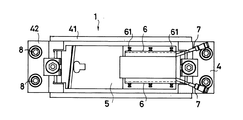
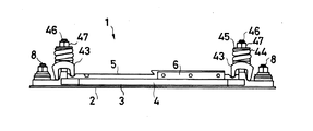
図1は本発明の電気融雪装置構成体を適用したスラブ分岐器を、床板上に支持されるレールの作図を省略して示した平面図、図2は図1の状態からヒータを取り外した場合の正面図である。
A preferred embodiment of the present invention will be described with reference to the drawings.
FIG. 1 is a plan view showing a slab branching device to which the electric snow melting apparatus structure of the present invention is applied without drawing a rail supported on a floor board, and FIG. 2 is a case where a heater is removed from the state of FIG. FIG.
図示されるように、この実施形態の融雪装置構成体1は、スラブ上に調整板2と軌道パッド3を重ねて配し、その上にレールを支持する床板5を載せ、この床板5の廻りには横圧受け金具4を配するとともにこれをボルト留めしてスラブ上に固定され、また、床板5のトングレールを支持する支持部両側面にそれぞれヒータ保持枠6、6が一体に設けられ、このヒータ保持枠6内に装填され保持されたヒータ7で床板5を加熱することができるように構成してある。
As shown in the figure, in the snow
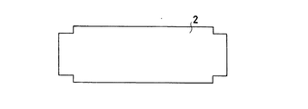
詳しくは、調節板2は、エポキシ樹脂を主成分とする混合物をガラスクロスに含浸させて形成された基材を複数積層し、分岐器が設置される現場のスラブ板の状態に合わせて適宜な厚みにプレス成形してなっている。調節板2は、床板5の下面が略一杯に重なって載る大きさであって、図3に示されるように、後述する絶縁板と干渉しないように矩形板の四隅を切り欠いた形状に形成してある。
Specifically, the
軌道パッド3は、高強度タイプのシリコンゴムを用いて適宜な厚みで且つ調節板2よりも若干大きな寸法形状に成形され、調節板2の上に重ね合わさる構造に設けてある。
The
横圧受け金具4は、図4に示されるように、ボルト挿通孔41a、41aを有する横圧受板41、41の両側に鋼材42、42を溶着して枠状に形成されている。横圧受板41、41には鉤状凹部41cを上縁に開口させた突段部41bが設けてあり、横圧受け金具4はこの鉤状凹部41cに、床板押さえ金具43、コイルばね44及び座金45を挿通させたT字ボルト46の端部を係合させ、床板押さえ金具43の縁部を床板5の凹溝5aに係合させた状態でT字ボルト46の他端部にナット47を締着して、横圧受板41、41の間に床板5を固定できるようになっている(図2参照)。また、図4中の側面図に表れているように、対向する横圧受板41、41の一方の突段部41bが他方の突段部41bよりも幅狭に設けてあり、つまり突段部41bの両側を切り欠き、床板5に固定されるヒータ7の端部が突段部41bに衝突しないようにしてある。
As shown in FIG. 4, the lateral pressure receiving
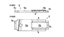
床板5は、図5に示されるように、矩形鋼材の上面に基本レールを支持する支持部5aとそれよりも高く突出したトングレールを支持する支持部5bを設け、両端に前記床板押さえ金具43の縁部が係入する凹溝5c、5cを設けて形成してある。また、支持部5bの両側面にはヒータ保持枠6、6が一体に固着してある。
As shown in FIG. 5, the
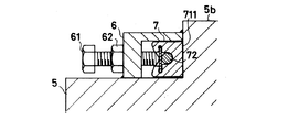
ヒータ保持枠6、6は、図6に示されるように、断面L字形の長尺鋼材からなり、その立面部6aと上面部6bの縁部を床板5に接合させて床板5の側面に一体に固着されている。ヒータ保持枠6の立面部6aにはヒータ7を固定するためのボルト61が挿通する複数の通孔6cを設けてある。
As shown in FIG. 6, the
ヒータ7は、図7及び図8に示されるように、外装材であるアルミニウム製の外装体71内に、発熱体としての管状のヒータ本体72と、断熱材としてのステンレス板73を挿入して構成してある。
詳しくは、外装体71は、押出し成形によりヒータ保持枠6内に挿入可能な厚みで長尺に形成され、図7に示されるように、その一側を前記床板5の支持部5bの側面に密着して接触可能な平面部711とし、その他側には、外装体の長手方向に連続して伸びた凹状の溝部712を設けてある。
溝部712は、外装体の略中央部でヒータ本体72の外径と略同じ内径で中空状に空けられた空間部712aに、ステンレス板73が嵌入し得る幅及び厚みのスリット712bを連ねて形成されており、スリット712bの外側には、溝部712を挟んで向かい合わせに係止片712c、712cを突出させてある。また、外装体71は、その先端からヒータ保持枠6と略同じ長さ分の位置で緩やかに屈曲させてある。
また、管状のヒータ本体72とステンレス板73は、ともに外装体71と略同じ長さに設けてあり、それぞれヒータ本体72は前記空間部712a内に略一杯に挿入し、ステンレス板73は前記スリット712c内に嵌入するようになっている。
ヒータ7は、外装体71の溝部712の空間部712a内にヒータ本体72を挿入し、挿入されたヒータ本体72の端部には給電コネクタ72aを接続しておき、さらにスリット712b内にステンレス板73を嵌入し、この状態で係止片712c、712cをステンレス板73側に折り曲げて溝部712の内方にかしめ、ヒータ本体72とステンレス板73を外装体内部に固定することにより構成される。
床板5へのヒータ7、7の取り付けは、図9に示されるように、ヒータ7の平面部711が床板5の側面に接触するようにヒータ7を横向きにしてヒータ保持枠6内にそれぞれ装填し、ヒータ保持枠6の各通孔6cにナット62を挟んでボルト61を螺子入れ、ボルト61の先端で前記係止片712c、712cでかしめたヒータ7の端部を押圧し、平面部711を床板支持部5bの側面に密着させることにより行われる。
As shown in FIGS. 7 and 8, the
Specifically, the
The
The tubular heater
The
As shown in FIG. 9, the
これらの部材からなる本形態の融雪装置構成体1は、スラブ上に調節板2と軌道パッド3を重ね、その上に床板5を設置し、さらに床板5の両側のスラブ上に絶縁板を設置し、絶縁板上に横圧受け金具4を載せ、横圧受け金具4と絶縁板にアンカーボルト8を通してスラブに固定し、横圧受け金具4に取り付けた床板押さえ金具43、43で床板5を固定して設置される。スラブ上に固定された床板5の上面には、その支持部5a上に基本レールが敷設され、支持部5b上にはトングレールが敷設され、支持部5bの側面に一体に固着されたヒータ保持枠6、6内にヒータ7、7をそれぞれ装填しボルト止めにより固定して融雪装置構成体1及びレール分岐器の取り付けが完了する。
The snow
このように設置された融雪装置構成体1は、床板5のトングレールを支持する支持部5bの両側面にヒータ7、7が取り付けられており、支持部5bに両ヒータ7の熱を集中させて床板5を効率的に加熱し、降雪時の積雪や凍結によってトングレールが作動不能となることを防止する。また、調節板2と軌道パッド3は高い耐熱性を有しているのでヒータ7の加熱によっても劣化が生じる虞れはなく、ヒータ7で床板5を高温に加熱することが可能である。ヒータ7は、ヒータ保持枠6で床板5の側面にしっかりと固定され、レールの可動や車両通過時の振動などによっても外れる虞れはない。
ヒータ7はその曲げ半径が限定されて大きく屈曲させることはできないが、横圧受け金具4の一方の横圧受板41の突段部41bを幅狭に設けてヒータ7の端部の配置空間を確保しているので、ヒータ7の端部が横圧受け板41に当たることはなく、ヒータ7の着脱を簡便に行うことが可能である。
In the snow
The
図10は他の実施形態を示し、これはヒータ7の端部をアダプタ74を介してU字形に屈曲し、アダプタ74と接続した給電ケーブル75を横圧受け金具4の側面に配した防護管76を通して配線したものである。アダプタ74で給電ケーブル75を任意の方向に屈曲させることにより、分岐器が設置される現場の状況に応じて配線することが可能である。図11は、ヒータ7の端部をアダプタ74を介して適宜な角度及び方向に屈曲させた他の形態を示している。
FIG. 10 shows another embodiment, in which the end portion of the
なお、図示した形態は一例であり、本発明の電気融雪装置構成体及びその構成部材は、分岐器の設置状況に応じて、各々他の適宜な構成や形状、形態に設けることが可能である。 The illustrated form is an example, and the electric snow melting apparatus structure and its constituent members of the present invention can be provided in other appropriate configurations, shapes, and forms, depending on the installation status of the branching device. .
1 融雪装置構成体、2 調節板、3 軌道パッド、4 横圧受け金具、5 床板、6 ヒータ保持枠、7 ヒータ、8 アンカーボルト
DESCRIPTION OF
Claims (1)
前記スラブと床板の間に重ねて設置される、耐熱性を与えて形成された調節板及び軌道パッドと、
断面L字形の長尺鋼材からなり、その直角に折れた立面部と上面部の縁部が前記床板に一体に固着されて前記床板のトングレールを支持する支持部の側面に接合してなるヒータ保持枠と、
外周面が前記床板の側面に密着して接触する形状に形成された高熱伝導率の金属材からなる外装材の内部に、線状又は棒状に形成されたヒータ本体を挿入して一体化してなるヒータとを備え、
前記ヒータ保持枠内に装填されたヒータがその外装材周面を前記床板のトングレール支持部側面に接触させた状態に保持して取り付けられた構成を有することを特徴とするスラブ分岐器用電気融雪装置構成体。 In the electric snow melting apparatus structure for a slab branching device for heating a rail branching device supported on a floor plate fixed on the slab with a lateral pressure receiving metal fitting,
An adjustment plate and a track pad that are installed to be heat-resistant and are installed between the slab and the floor plate;
It is made of a long steel material having an L-shaped cross section, and is formed by joining the side surface of the support portion that supports the tongrel of the floor plate, with the rising edge portion and the edge portion of the upper surface portion thereof fixed integrally to the floor plate. A heater holding frame;
A heater body formed in a linear shape or a rod shape is integrated into an exterior material made of a metal material having a high thermal conductivity formed so that its outer peripheral surface is in close contact with the side surface of the floor plate. With a heater,
An electric snow melting device for a slab branching device having a structure in which a heater loaded in the heater holding frame is attached while holding a peripheral surface of an exterior material in contact with a side surface of a tongrel support portion of the floor board. Device structure.
Priority Applications (1)
| Application Number | Priority Date | Filing Date | Title |
|---|---|---|---|
| JP2005052754A JP4831460B2 (en) | 2005-02-28 | 2005-02-28 | Electric snow melting device structure for slab turnout |
Applications Claiming Priority (1)
| Application Number | Priority Date | Filing Date | Title |
|---|---|---|---|
| JP2005052754A JP4831460B2 (en) | 2005-02-28 | 2005-02-28 | Electric snow melting device structure for slab turnout |
Publications (2)
| Publication Number | Publication Date |
|---|---|
| JP2006233680A JP2006233680A (en) | 2006-09-07 |
| JP4831460B2 true JP4831460B2 (en) | 2011-12-07 |
Family
ID=37041641
Family Applications (1)
| Application Number | Title | Priority Date | Filing Date |
|---|---|---|---|
| JP2005052754A Expired - Lifetime JP4831460B2 (en) | 2005-02-28 | 2005-02-28 | Electric snow melting device structure for slab turnout |
Country Status (1)
| Country | Link |
|---|---|
| JP (1) | JP4831460B2 (en) |
Families Citing this family (1)
| Publication number | Priority date | Publication date | Assignee | Title |
|---|---|---|---|---|
| JP6212616B1 (en) * | 2016-09-26 | 2017-10-11 | 大和軌道製造株式会社 | Sleeper floor structure |
Family Cites Families (6)
| Publication number | Priority date | Publication date | Assignee | Title |
|---|---|---|---|---|
| JPS56150201U (en) * | 1980-04-02 | 1981-11-11 | ||
| JP2522405Y2 (en) * | 1991-11-14 | 1997-01-16 | 株式会社新陽社 | Heater crimping tool for floor plate heating |
| JPH07247502A (en) * | 1994-03-11 | 1995-09-26 | Daiwa Kogyo Kk | Elastic fastening structure for turnout |
| JPH0814327A (en) * | 1994-06-24 | 1996-01-16 | Ryobi Ltd | Vibration proof pad |
| JP2000257001A (en) * | 1999-03-04 | 2000-09-19 | Yamato Kogyo Co Ltd | Joining structure of bed plate for turnout |
| JP2001295207A (en) * | 2000-02-10 | 2001-10-26 | Sekisui Chem Co Ltd | How to repair holes in synthetic wood |
-
2005
- 2005-02-28 JP JP2005052754A patent/JP4831460B2/en not_active Expired - Lifetime
Also Published As
| Publication number | Publication date |
|---|---|
| JP2006233680A (en) | 2006-09-07 |
Similar Documents
| Publication | Publication Date | Title |
|---|---|---|
| US7064301B2 (en) | Electric heater | |
| JP6112428B2 (en) | Heat exchanger | |
| JP2718764B2 (en) | Equipment for heating gas | |
| KR101479070B1 (en) | Ptc heater | |
| US20140305924A1 (en) | Heatable Current Collector for Establishing an Electrical Contact Between a Current Carrying Line and an Electric Vehicle | |
| JP2010537412A (en) | Electric heat converter and temperature control device | |
| JP2005217399A (en) | Control unit having thermal protection device and electric heating device comprising the control unit | |
| KR102030200B1 (en) | Insulated heating module for a supplemental heating device | |
| KR100759533B1 (en) | Cover-mounted car preheater | |
| JP2018523255A (en) | Electrical energy transfer system for wire mesh heaters | |
| KR20110041656A (en) | Pre heater assembly | |
| JP4831460B2 (en) | Electric snow melting device structure for slab turnout | |
| KR101629932B1 (en) | Pre heater device for vehicle | |
| KR101694712B1 (en) | Pre heater device for vehicle | |
| JP4524324B2 (en) | Bond and bond bonding method | |
| KR101738858B1 (en) | Inverter welding device | |
| KR101532950B1 (en) | Heating device for adhesion of panel and pad | |
| JP3653116B2 (en) | Point heater | |
| JP3572412B2 (en) | Hot plate | |
| KR100747900B1 (en) | PTC heater with improved coupling structure | |
| JP2015232211A (en) | Snow-melting apparatus | |
| KR101694713B1 (en) | Pre heater device for vehicle | |
| KR20140099782A (en) | Ptc heater | |
| KR20250113882A (en) | Vehicle interior with power supply connectors | |
| JP4944710B2 (en) | Floor pan heating structure |
Legal Events
| Date | Code | Title | Description |
|---|---|---|---|
| A711 | Notification of change in applicant |
Free format text: JAPANESE INTERMEDIATE CODE: A711 Effective date: 20080128 |
|
| A621 | Written request for application examination |
Free format text: JAPANESE INTERMEDIATE CODE: A621 Effective date: 20080131 |
|
| A521 | Request for written amendment filed |
Free format text: JAPANESE INTERMEDIATE CODE: A821 Effective date: 20080128 |
|
| A521 | Request for written amendment filed |
Free format text: JAPANESE INTERMEDIATE CODE: A523 Effective date: 20080319 |
|
| A977 | Report on retrieval |
Free format text: JAPANESE INTERMEDIATE CODE: A971007 Effective date: 20100312 |
|
| A131 | Notification of reasons for refusal |
Free format text: JAPANESE INTERMEDIATE CODE: A131 Effective date: 20100330 |
|
| A521 | Request for written amendment filed |
Free format text: JAPANESE INTERMEDIATE CODE: A523 Effective date: 20100528 |
|
| A521 | Request for written amendment filed |
Free format text: JAPANESE INTERMEDIATE CODE: A523 Effective date: 20100602 |
|
| A521 | Request for written amendment filed |
Free format text: JAPANESE INTERMEDIATE CODE: A523 Effective date: 20100602 |
|
| A131 | Notification of reasons for refusal |
Free format text: JAPANESE INTERMEDIATE CODE: A131 Effective date: 20101207 |
|
| A521 | Request for written amendment filed |
Free format text: JAPANESE INTERMEDIATE CODE: A523 Effective date: 20110207 |
|
| TRDD | Decision of grant or rejection written | ||
| A01 | Written decision to grant a patent or to grant a registration (utility model) |
Free format text: JAPANESE INTERMEDIATE CODE: A01 Effective date: 20110809 |
|
| A01 | Written decision to grant a patent or to grant a registration (utility model) |
Free format text: JAPANESE INTERMEDIATE CODE: A01 |
|
| A61 | First payment of annual fees (during grant procedure) |
Free format text: JAPANESE INTERMEDIATE CODE: A61 Effective date: 20110908 |
|
| FPAY | Renewal fee payment (event date is renewal date of database) |
Free format text: PAYMENT UNTIL: 20140930 Year of fee payment: 3 |
|
| R150 | Certificate of patent or registration of utility model |
Ref document number: 4831460 Country of ref document: JP Free format text: JAPANESE INTERMEDIATE CODE: R150 Free format text: JAPANESE INTERMEDIATE CODE: R150 |
|
| R250 | Receipt of annual fees |
Free format text: JAPANESE INTERMEDIATE CODE: R250 |
|
| R250 | Receipt of annual fees |
Free format text: JAPANESE INTERMEDIATE CODE: R250 |
|
| R250 | Receipt of annual fees |
Free format text: JAPANESE INTERMEDIATE CODE: R250 |
|
| R250 | Receipt of annual fees |
Free format text: JAPANESE INTERMEDIATE CODE: R250 |
|
| R250 | Receipt of annual fees |
Free format text: JAPANESE INTERMEDIATE CODE: R250 |
|
| R250 | Receipt of annual fees |
Free format text: JAPANESE INTERMEDIATE CODE: R250 |
|
| R250 | Receipt of annual fees |
Free format text: JAPANESE INTERMEDIATE CODE: R250 |
|
| S111 | Request for change of ownership or part of ownership |
Free format text: JAPANESE INTERMEDIATE CODE: R313117 |
|
| S531 | Written request for registration of change of domicile |
Free format text: JAPANESE INTERMEDIATE CODE: R313531 |
|
| R350 | Written notification of registration of transfer |
Free format text: JAPANESE INTERMEDIATE CODE: R350 |
|
| R250 | Receipt of annual fees |
Free format text: JAPANESE INTERMEDIATE CODE: R250 |
|
| R250 | Receipt of annual fees |
Free format text: JAPANESE INTERMEDIATE CODE: R250 |
|
| R250 | Receipt of annual fees |
Free format text: JAPANESE INTERMEDIATE CODE: R250 |
|
| R250 | Receipt of annual fees |
Free format text: JAPANESE INTERMEDIATE CODE: R250 |
|
| EXPY | Cancellation because of completion of term |