JP4831486B2 - Thin section specimen preparation device and thin section specimen preparation method - Google Patents
Thin section specimen preparation device and thin section specimen preparation method Download PDFInfo
- Publication number
- JP4831486B2 JP4831486B2 JP2006340187A JP2006340187A JP4831486B2 JP 4831486 B2 JP4831486 B2 JP 4831486B2 JP 2006340187 A JP2006340187 A JP 2006340187A JP 2006340187 A JP2006340187 A JP 2006340187A JP 4831486 B2 JP4831486 B2 JP 4831486B2
- Authority
- JP
- Japan
- Prior art keywords
- thin
- section
- holding
- holding frame
- range
- Prior art date
- Legal status (The legal status is an assumption and is not a legal conclusion. Google has not performed a legal analysis and makes no representation as to the accuracy of the status listed.)
- Active
Links
Images


Landscapes
- Sampling And Sample Adjustment (AREA)
Description
本発明は、人体や実験動物等から取り出した生体試料を包埋した包埋ブロックから作製した薄切片を、スライドガラス上に載置して薄切片標本を作製する薄切片標本作製装置及び薄切片標本の作製方法に関する。 The present invention relates to a thin-section specimen preparation device and a thin-section specimen for preparing a thin-section specimen by placing a thin section prepared from an embedding block in which a biological sample taken out of a human body or a laboratory animal is embedded on a slide glass The present invention relates to a specimen preparation method.
従来から、人体や実験動物等から取り出した生体試料を検査、観察する方法の1つとして、包埋剤によって生体試料を包埋した包埋ブロックから薄切片を作製して生体試料の観察を行う方法が知られている。より詳しくは、包埋ブロックから作製された薄切片をプレート上に載置して薄切片標本を作製し、プレート上において薄切片に含まれた生体試料に染色処理を行って、生体試料の観察が行われる。 Conventionally, as one method for inspecting and observing a biological sample taken from a human body or a laboratory animal, a thin section is prepared from an embedding block in which the biological sample is embedded with an embedding agent, and the biological sample is observed. The method is known. More specifically, a thin section prepared from an embedding block is placed on a plate to prepare a thin section specimen, and the biological sample contained in the thin section is stained on the plate to observe the biological sample. Is done.
ここで、例えば前臨床試験においては、一試験当たり数百個の包埋ブロックを作製し、さらに一包埋ブロック当たり数枚の薄切片標本を作製する。このため、作業者は膨大な枚数の薄切片標本を作製する必要があるため、近年、包埋ブロックから薄切片標本を作製するまでの一連の工程を行うことが可能な薄切片標本作製装置が開発されていきている。このような薄切片標本作製装置としては、切削された薄切片を搬送する搬送手段と、プレート上に接着用水を滴下させ、該接着用水を介して搬送手段によって搬送される薄切片をプレート上に転写させる転写手段と、加熱してプレート上の薄切片を伸展させる伸展装置を備えたものが提案されている(例えば、特許文献1参照)。このような薄切片標本作製装置によれば、作製した薄切片を薄切片搬送手段によってプレートまで搬送し、転写手段によって薄切片をプレートに転写して薄切片標本を作製することができるとされている。また、伸展装置によって加熱することで、プレート上の接着用水を蒸発させて、プレートに載置された薄切片の皺を伸ばしてプレートに貼り付けることができるとされている。
しかしながら、特許文献1による装置及び方法において、転写手段によってプレート上に供給される接着用水は、プレートの表面との表面張力のみによってプレート上に保持されている。従って、プレート上に保持可能な接着用水には限界があり、それ故に搬送手段からプレート上に薄切片を確実に受け渡すことができない場合があった。また、薄切片がプレート上に受け渡されたとしても、プレート上で接着用水が流動してしまい、接着用水とともに、薄切片が移動、あるいは、流出してしまう場合があった。さらに、上記のように十分な接着用水を保持することができないが故に、プレート上に薄切片を載置する際に、薄切片とプレートとの間に気泡が巻き込まれてしまう場合があった。このような場合には、次工程において伸展装置で加熱伸展したとしても、気泡によりプレートと薄切片との間に隙間が生じ、伸展せずに皺が生じてしまう。このため、特許文献1による装置及び方法では、歩留まりが低下してしまい、また、薄切片に皺が無い一定の品質の薄切片標本を得ることが困難であった。 However, in the apparatus and method according to Patent Literature 1, the bonding water supplied onto the plate by the transfer means is held on the plate only by the surface tension with the surface of the plate. Accordingly, there is a limit to the bonding water that can be held on the plate, and therefore, there has been a case where the thin section cannot be reliably transferred from the conveying means onto the plate. Further, even when the thin slice is transferred onto the plate, the bonding water flows on the plate, and the thin slice may move or flow out together with the bonding water. Furthermore, since sufficient bonding water cannot be retained as described above, when a thin slice is placed on the plate, air bubbles may be caught between the thin slice and the plate. In such a case, even if it is heated and stretched by the stretching device in the next process, a gap is generated between the plate and the thin section by the bubbles, and wrinkles are generated without stretching. For this reason, with the apparatus and method according to Patent Document 1, the yield is reduced, and it is difficult to obtain a thin slice specimen of a certain quality with no wrinkles in the thin slice.
この発明は、上述した事情に鑑みてなされたものであって、プレート上に確実に薄切片を載置して、歩留まり良く、薄切片に皺が無い一定の品質の薄切片標本を作製することが可能な薄切片標本作製装置、及び、薄切片標本の作製方法を提供するものである。 The present invention has been made in view of the above-described circumstances, and is intended to reliably place a thin section on a plate, and to produce a thin section specimen of a certain quality with a high yield and no wrinkles in the thin section. A thin-section specimen preparation apparatus and a thin-section specimen preparation method are provided.
上記課題を解決するために、この発明は以下の手段を提案している。
本発明は、生体試料が包埋剤によって包埋された包埋ブロックを所定の厚さで切削することで作製された薄切片を、プレート上に載置して薄切片標本を作製する薄切片標本作製装置であって、略枠状で疎水性の膜で形成された保持枠を、前記プレートの表面の内、少なくとも前記薄切片が載置される載置範囲を含む保持範囲を囲むように形成する保持枠形成手段と、該保持範囲内に、接着用水を供給する接着用水供給手段と、該接着用水を有した状態の前記プレートを載置する載置台と、前記包埋ブロックから作製された前記薄切片を搬送し、前記載置台上に載置された前記プレートの前記載置範囲内に前記薄切片を載置する搬送手段とを備えることを特徴としている。
In order to solve the above problems, the present invention proposes the following means.
The present invention provides a thin slice prepared by placing a thin slice prepared by cutting an embedded block in which a biological sample is embedded with an embedding agent at a predetermined thickness on a plate to produce a thin slice specimen. A specimen preparation device, wherein a holding frame formed of a substantially frame-like and hydrophobic film surrounds a holding range including at least a mounting range on which the thin slice is mounted on the surface of the plate. The holding frame forming means to be formed, the bonding water supply means for supplying the bonding water within the holding range, the mounting table for mounting the plate in a state having the bonding water, and the embedding block are produced. And transporting means for transporting the thin section and mounting the thin section within the mounting range of the plate mounted on the mounting table.
また、本発明は、生体試料が包埋剤によって包埋された包埋ブロックを所定の厚さで切削することで作製された薄切片を、プレート上に載置して薄切片標本を作製する薄切片標本の作製方法であって、略枠状で疎水性の膜で形成された保持枠を、前記プレートの表面の内、少なくとも前記薄切片が載置される載置範囲を含む保持範囲を囲むように形成する保持枠形成工程と、該保持範囲内に、接着用水を供給する接着用水供給工程と、該接着用水を有する前記プレートの前記載置範囲内に、前記薄切片を載置する薄切片載置工程とを備えることを特徴としている。 Further, the present invention produces a thin slice specimen by placing a thin section prepared by cutting an embedded block in which a biological sample is embedded with an embedding agent at a predetermined thickness on a plate. A method for producing a thin-section specimen, comprising a holding frame formed of a substantially frame-like and hydrophobic film, the holding range including at least a mounting range in which the thin section is mounted on the surface of the plate A holding frame forming step that is formed so as to surround, a bonding water supply step that supplies bonding water in the holding range, and the thin section is placed in the mounting range of the plate having the bonding water. And a thin-section placing step.
この発明に係る薄切片標本作製装置及び薄切片標本の作製方法によれば、保持枠形成工程として、保持枠形成手段によって、プレートの表面上で、薄切片が載置される載置範囲を含む保持範囲を囲むように、略枠状の保持枠が形成される。次に、接着用水供給工程として、接着用水供給手段によって、プレートの表面上の保持範囲に必要量の接着用水を供給する。保持枠は疎水性の膜で形成されているので、供給された接着用水は、保持枠より内側で保持範囲に、供給された量に応じた厚さを有して確実に保持された状態となる。このため、薄切片載置工程として、載置台に、接着用水を有した状態のプレートを載置し、搬送手段によって薄切片を搬送してプレート上の載置範囲内に載置すれば、接着用水によって搬送手段からプレートに確実に薄切片を受け渡すことができ、また、移動あるいは流出してしまうことなく確実に薄切片を載置範囲に保持することができる。また、十分な接着用水を保持することができる故に、気泡を巻き込むこと無く、プレートの載置範囲に薄切片を載置することができる。 According to the thin-section specimen preparation apparatus and the thin-section specimen preparation method according to the present invention, the holding frame forming step includes a mounting range in which the thin section is placed on the surface of the plate by the holding frame forming means. A substantially frame-shaped holding frame is formed so as to surround the holding range. Next, as a bonding water supply step, a required amount of bonding water is supplied to the holding range on the surface of the plate by the bonding water supply means. Since the holding frame is formed of a hydrophobic film, the supplied bonding water is securely held in the holding range inside the holding frame with a thickness corresponding to the supplied amount. Become. For this reason, as a thin slice placement step, if a plate with adhesive water is placed on the placement table, the thin slice is transported by the transport means and placed within the placement range on the plate, the adhesive The thin section can be reliably transferred from the transport means to the plate by the irrigation water, and the thin section can be reliably held in the placement range without moving or flowing out. In addition, since a sufficient amount of water for bonding can be retained, the thin slice can be placed in the plate placement range without entraining bubbles.
また、上記の薄切片標本作製装置において、前記保持枠形成手段は、前記保持範囲として、前記載置範囲から外側に突出した突出部を有するように、前記保持枠の一部を突出して形成可能であることがより好ましいとされている。
また、上記の薄切片標本の作製方法において、前記保持枠形成工程は、前記保持範囲として、前記載置範囲から外側に突出した突出部を有するように、前記保持枠の一部を突出させて形成することがより好ましいとされている。
In the thin-section specimen preparation apparatus, the holding frame forming means can be formed by protruding a part of the holding frame so that the holding range has a protruding portion protruding outward from the placement range. It is said that it is more preferable.
Further, in the above method for preparing a sliced piece specimen, the holding frame forming step includes projecting a part of the holding frame so that the holding range has a protruding portion protruding outward from the placement range. It is more preferable to form.
この発明に係る薄切片標本作製装置及び薄切片標本の作製方法によれば、保持枠形成工程において、保持枠形成手段によって、保持枠の一部を突出させることで、保持枠で形成される保持範囲を、載置範囲から外側に突出した突出部を有するものとすることができる。このため、薄切片載置工程によってプレートの載置範囲に薄切片を載置した状態で、薄切片の外側に、保持範囲の一部を突出した状態で露出させることができ、薄切片載置後も、必要に応じて、接着用水を供給、吸水し、接着用水の量をコントロールすることが可能となる。 According to the thin-section specimen preparation device and the thin-section specimen preparation method according to the present invention, in the holding frame forming step, the holding frame is formed by holding the holding frame by causing the holding frame forming means to project a part of the holding frame. The range may have a protruding portion that protrudes outward from the placement range. For this reason, in a state where the thin slice is placed in the plate placement range by the thin slice placement step, it is possible to expose a part of the holding range to protrude outside the thin slice. After that, if necessary, it is possible to supply and absorb the bonding water and control the amount of the bonding water.
さらに、上記の薄切片標本作製装置において、前記保持範囲の前記突出部から露出する前記接着用水を吸水する吸水手段を備えることがより好ましいとされている。
さらに、上記の薄切片標本の作製方法において、前記薄切片載置工程後に、前記保持範囲の前記突出部から露出する前記接着用水を吸水する吸水工程を備えることがより好ましいとされている。
Furthermore, in the above-described thin-section specimen preparation device, it is more preferable that the thin-section specimen preparation device further includes a water absorbing means for absorbing the bonding water exposed from the protruding portion of the holding range.
Furthermore, in the method for producing a thin-section specimen, it is more preferable to include a water-absorbing step of absorbing the bonding water exposed from the protruding portion of the holding range after the thin-section placing step.
この発明に係る薄切片標本作製装置及び薄切片標本の作製方法によれば、吸水工程として、吸水手段によって、保持範囲の突出部から接着用水を吸水すれば、薄切片とプレートとの間に介装された接着用水を取り除くことができる。すなわち、薄切片載置工程では必要な接着用水を保持した状態で薄切片を載置することができる一方、薄切片載置工程後では余分な接着用水を除去することができる。 According to the thin-section specimen preparation device and the thin-section specimen preparation method according to the present invention, if the water for bonding is absorbed from the protruding portion of the holding range by the water absorption means as the water absorption step, the thin section specimen preparation method is interposed between the thin section and the plate. The attached adhesive water can be removed. That is, in the thin slice placement step, the thin slice can be placed in a state where necessary adhesive water is held, but after the thin slice placement step, excess bonding water can be removed.
また、上記の薄切片標本作製装置において、前記保持枠形成手段は、前記プレートの前記表面に前記保持枠を複数形成可能であることがより好ましいとされている。
また、上記の薄切片標本の作製方法において、前記保持枠形成工程は、前記プレートの前記表面に前記保持枠を複数形成するとともに、前記接着用水供給工程及び前記薄切片載置工程は、複数の前記保持枠で形成された前記保持範囲のそれぞれに、前記接着用水を供給し、前記薄切片を載置することがより好ましいとされている。
In the thin-section specimen preparation apparatus, it is more preferable that the holding frame forming means can form a plurality of the holding frames on the surface of the plate.
In the method for preparing a thin-section specimen, the holding frame forming step forms a plurality of the holding frames on the surface of the plate, and the bonding water supply step and the thin-section placing step include a plurality of holding frames. More preferably, the bonding water is supplied to each of the holding ranges formed by the holding frame and the thin slice is placed.
この発明に係る薄切片標本作製装置及び薄切片標本の作製方法によれば、保持枠形成工程において、保持枠形成手段によって保持枠を複数形成することで、各保持枠によって、薄切片を載置可能な載置範囲を含む保持範囲を複数形成することができる。このため、一つのプレート上に複数の薄切片を載置することができる。ここで、各載置範囲は、対応する保持枠によって囲まれていることで、載置された薄切片が隣接する載置範囲に移動してしまい、あるいは、隣接する載置範囲から異物が混入してしまうことを防ぐことができる。 According to the thin-section specimen preparation device and the thin-section specimen preparation method according to the present invention, in the holding frame forming step, a plurality of holding frames are formed by the holding frame forming means, so that the thin sections are placed by each holding frame. A plurality of holding ranges including possible placement ranges can be formed. For this reason, a plurality of thin slices can be placed on one plate. Here, because each placement range is surrounded by the corresponding holding frame, the placed thin section moves to the adjacent placement range, or foreign matter enters from the adjacent placement range. Can be prevented.
また、上記の薄切片標本作製装置において、前記保持枠形成手段は、前記保持枠を、前記包埋剤によって形成することがより好ましいとされている。
また、上記の薄切片標本の作製方法において、前記保持枠形成工程は、前記保持枠を、前記包埋剤によって形成することがより好ましいとされている。
In the thin-section specimen preparation device, the holding frame forming means preferably forms the holding frame with the embedding agent.
In the method for producing a thin-section specimen, the holding frame forming step preferably forms the holding frame with the embedding agent.
この発明に係る薄切片標本作製装置及び薄切片標本の作製方法によれば、保持枠は、保持枠形成工程において、保持枠形成手段によって包埋剤で形成されることで、載置範囲に載置される薄切片と同一材質とすることができる。このため、薄切片標本作製後は、プレート上の薄切片に含まれる包埋剤を除去する工程に応じて同時に除去することができ、その後の薄切片に含まれる生体試料に染色する工程において支障となってしまうことが無い。 According to the thin-section specimen preparation device and the thin-section specimen preparation method according to the present invention, the holding frame is mounted on the placement range by being formed of the embedding agent by the holding frame forming means in the holding frame forming step. The same material as the thin slice to be placed can be used. For this reason, after the preparation of a thin slice specimen, it can be removed at the same time according to the step of removing the embedding agent contained in the thin slice on the plate, which hinders the subsequent process of staining the biological sample contained in the thin slice. There is no end.
本発明の薄切片標本作製装置によれば、保持枠形成手段を備えることで、保持枠で形成された保持範囲に接着用水を確実に保持し、プレートと薄切片との間に気泡が発生してしまうこと無く、確実に薄切片をプレート上に受け渡して、載置することができる。このため、歩留まり良く、薄切片に皺が無い一定の品質を有した薄切片標本を作製することができる。
本発明の薄切片標本の作製方法によれば、保持枠形成工程を備えることで、保持枠で形成された保持範囲に接着用水を確実に保持し、プレートと薄切片との間に気泡が発生してしまうこと無く、確実に薄切片をプレート上に受け渡して、載置することができる。このため、歩留まり良く、薄切片に皺が無い一定の品質を有した薄切片標本を作製することができる。
According to the thin-section sample preparation device of the present invention, by providing the holding frame forming means, the bonding water is reliably held in the holding range formed by the holding frame, and bubbles are generated between the plate and the thin section. Therefore, the thin slice can be reliably delivered and placed on the plate. For this reason, it is possible to produce a thin slice specimen with a high yield and a certain quality with no defects in the thin slice.
According to the method for preparing a sliced piece specimen of the present invention, by providing a holding frame forming step, water for bonding is securely held in the holding range formed by the holding frame, and bubbles are generated between the plate and the sliced piece. Therefore, the sliced piece can be reliably delivered and placed on the plate. For this reason, it is possible to produce a thin slice specimen with a high yield and a certain quality with no defects in the thin slice.
(第1の実施形態)
図1から図5は、この発明に係る実施形態を示している。図1に示す薄切片標本作製装置1は、生体試料Sが包埋された包埋ブロックを切削して厚さ3〜5μm程度の極薄の薄切片Bを作製し、薄切片Bに含まれる生体試料Sを検査、観察する過程において、薄切片Bを、スライドガラス(プレート)P1上の所定の載置範囲P3に載置して薄切片標本Pを作製する装置である。生体試料Sは、例えば、人体や実験動物等から取り出した臓器などの組織から切除された試料であり、医療分野、製薬分野、食品分野、生物分野などで適時選択されるものである。また、包埋ブロックは、上記のような生体試料Sを包埋剤B1によって包埋、すなわち周囲を覆い固めたものであり、生体試料Sは、通常、その種類毎に向きを統一させて包埋されている。このような包埋ブロックは、より詳しくは、以下のように作製されるものである。まず、上記の生体試料Sの塊をホルマリンに漬けて、生体試料Sを構成する蛋白質を固定する。そして、組織を固い状態にした後、適当な大きさに切断する。最後に、切断された生体試料Sの内部の水分を包埋剤B1に置き換えたものを、溶解した包埋剤B1の中に埋め込んで、固めることで作製される。ここで、包埋剤B1は、上記のように液状化と冷却固化が容易に可能とされるとともに、有機溶媒に浸漬することで溶解する材質で、樹脂やパラフィンなどである。本実施形態では、包埋剤B1としてパラフィンを使用している。そして、この包埋ブロックを切削することで、所定の厚さを有し、包埋剤B1の内部に生体試料Sを含んだ薄切片Bが作製される。
以下、薄切片標本作製装置1の構成について説明する。
(First embodiment)
1 to 5 show an embodiment according to the present invention. A thin-section specimen preparation apparatus 1 shown in FIG. 1 cuts an embedded block in which a biological sample S is embedded to prepare an ultrathin section B having a thickness of about 3 to 5 μm, and is included in the thin section B. In the process of inspecting and observing the biological sample S, the thin section B is placed on a predetermined placement range P3 on the slide glass (plate) P1 to produce the thin section specimen P. The biological sample S is, for example, a sample excised from a tissue such as an organ taken out of a human body or a laboratory animal, and is appropriately selected in the medical field, pharmaceutical field, food field, biological field, and the like. The embedding block is the above-described biological sample S embedded with the embedding agent B1, that is, the periphery is covered and hardened, and the biological sample S is usually wrapped in a uniform direction for each type. Buried. More specifically, such an embedding block is manufactured as follows. First, the mass of the biological sample S is immersed in formalin, and the protein constituting the biological sample S is fixed. And after making a structure | tissue solid, it cut | disconnects to a suitable magnitude | size. Finally, it is produced by embedding and solidifying a material obtained by replacing the moisture in the cut biological sample S with the embedding agent B1. Here, the embedding agent B1 is a material that can be easily liquefied and cooled and solidified as described above, and is dissolved by being immersed in an organic solvent, such as resin or paraffin. In this embodiment, paraffin is used as the embedding agent B1. Then, by cutting this embedding block, a thin slice B having a predetermined thickness and including the biological sample S inside the embedding agent B1 is produced.
Hereinafter, the configuration of the thin-section specimen preparation device 1 will be described.
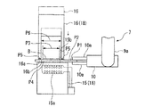
図1に示すように、薄切片標本作製装置1は、薄切片Bが載置されていないスライドガラスP1を収納するスライドガラス保管庫2と、作製された薄切片標本Pを収納する薄切片標本保管庫3と、スライドガラスP1を載置する載置面4aを有する載置台4と、包埋ブロックから作製された薄切片Bを搬送する搬送手段5と、各構成を制御する制御部6とを備える。また、スライドガラス保管庫2、薄切片標本保管庫3、及び、載置台4の間には、これらが配列するX軸方向及び上下方向であるZ軸方向にスライドガラスP1及び薄切片標本Pを搬送する手段であるハンドリングロボット7が設けられている。
As shown in FIG. 1, a thin-section sample preparation apparatus 1 includes a slide glass storage 2 for storing a slide glass P1 on which a thin section B is not placed, and a thin-section sample for storing the prepared thin section specimen P. The storage 3, the mounting table 4 having the mounting
ハンドリングロボット7は、Z軸方向に立設されたZ軸ガイドレール8と、Z軸ガイドレール8上でX軸方向に配設されたX軸ガイドレール9と、X軸ガイドレール9上に設けられてスライドガラスP1を把持する把持部10とを備える。Z軸ガイドレール8には、Zステージ8aがZ軸方向に移動自在に設けられている。また、X軸ガイドレール9は、Zステージ8aに取り付けられていて、これによりZ軸ガイドレール8上でZ軸方向に移動可能となっている。X軸ガイドレール9には、Xステージ9aがX軸方向に移動自在に設けられている。また、把持部10は、Xステージ9aに、X軸及びZ軸を含む面内で回転可能に取り付けられている。このため、把持部10は、X軸ガイドレール9上で、向きを自在に変化させながらX軸方向及びZ軸方向に移動可能となっている。また、把持部10は、一対のアーム10aを有していて、一対のアーム10aの間隔を変化させることによってスライドガラスP1の端部を挟持することが可能である。これにより、制御部6による制御のもと、スライドガラス保管庫2及び薄切片標本保管庫3のそれぞれと、載置台4との間で、スライドガラスP1及び薄切片標本Pを搬送することが可能である。
The handling robot 7 is provided on a Z-axis guide rail 8 erected in the Z-axis direction, an
搬送手段5は、X軸方向に沿って配設された搬送テープ11によって構成されている。搬送テープ11の両端は、図示しないが、それぞれローラに巻き取られている。また、搬送テープ11の上面11aには、図示しない帯電装置によってマイナスの電荷が与えられている。一方、搬送手段5によって搬送される薄切片Bには、図示しない他の帯電装置によってプラスの電荷が与えられている。このため、薄切片Bは、静電気によって、搬送テープ11の下面11bに貼り付けられた状態に保たれていている。また、搬送テープ11は、載置台4の前後において、第一の駆動ローラ12a及び第一の補助ローラ12b、並びに、第二の駆動ローラ13a及び第二の補助ローラ13bによって、それぞれ挟み込まれている。第一の駆動ローラ12a及び第二の駆動ローラ13aは、制御部6による制御のもと、図示しないモータによって、それぞれ独立して回転可能であり、これにより搬送テープ11をX軸方向に沿って前後に進退させて、下面11bに貼り付けられた薄切片Bを搬送することが可能である。また、制御部6による制御のもと、第一の駆動ローラ12a及び第二の駆動ローラ13aの回転方向を互いに異なる方向とすることで、載置台4の載置面4a上で搬送テープ11を弛ませ、また、緊張させることができる。そして、載置台4の載置面4aにスライドガラスP1を載置し、下面11bに貼り付けられた薄切片Bが載置台4の上方に位置した状態で搬送テープ11を弛ませれば、薄切片BをスライドガラスP1の表面P2に当接させることができる。
The transport means 5 is constituted by a
載置台4は、載置面4aにスライドガラスP1をX軸方向に進退可能なスライドガラスXステージ4bと、Z軸回りに回転させることが可能なスライドガラス回転ステージ4cとを備える。そして、制御部6による制御のもと、スライドガラスXステージ4b及びスライドガラス回転ステージ4cを駆動してスライドガラスP1の位置及び向きを調整することで、搬送手段5によって搬送された薄切片Bを、スライドガラスP1の表面P2において所望の載置範囲P3に、所望の向きで載置することができる。
The mounting table 4 includes, on the mounting
また、薄切片標本作製装置1は、スライドガラス保管庫2と載置台4との間において、スライドガラスP1を加熱する加熱装置15と、加熱装置15の上方に位置する枠材供給部16と、スライドガラスP1上に薄切片Bを貼り付けるための接着用水Wを供給する接着用水供給手段17とを備える。接着用水Wは、水を主成分とする液体であり、エチルアルコールなどを含むものとしても良い。そして、接着用水供給手段17は、制御部6による制御のもと、ハンドリングロボット7によって下方に搬送されたスライドガラスP1の表面P2に接着用水Wを滴下し、供給することが可能である。
The thin-section specimen preparation device 1 includes a
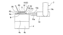
また、加熱装置15は、ヒータ15aを有していて、ハンドリングロボット7によって上面15b上に搬送されるスライドガラスP1を裏面P4から加熱することが可能である。なお、ヒータ15aに代えて赤外線ランプなどとしても良い。そして、スライドガラスP1上に載置された薄切片B及び接着用水Wを加熱することで、伸展装置として、薄切片Bのお湯伸展を行うことが可能である。また、加熱装置15の上方に位置する枠材供給部16は、疎水性の材質で形成されていて、本実施形態では、薄切片Bに含まれる包埋剤B1と同じくパラフィンで形成されている。図2に示すように、枠材供給部16は、下面16aに開口部16bを有していて、矩形の略枠状に形成されている。開口部16aの大きさは、薄切片Bが載置される載置範囲P3と略等しいか若しくは大きく設定されている。また、枠材供給部16は、制御部6の制御のもと、図示しない昇降手段によりZ軸方向に進退することが可能である。そして、枠材供給部16の下面16aがスライドガラスP1の表面P2に当接した状態として加熱装置15のヒータ15aによって加熱することで、枠材供給部16を形成するパラフィンを、載置範囲P3を囲むように溶融させて保持枠P5を形成することができ、すなわち、加熱装置15、枠材供給部16、及び、図示しない昇降手段によって保持枠形成手段18を構成している。
The
次に、この薄切片標本作製装置1の作用について説明する。図1に示すように、まず、準備工程として、制御部6は、ハンドリングロボット7を駆動し、ハンドリングロボット7によってスライドガラス保管庫2からスライドガラスP1を取り出させる。そして、枠材供給部16を上方に待機させた状態で、取り出したスライドガラスP1を加熱装置15の上面15b上に配置させる。次に、図2及び図3に示すように、保持枠形成工程として、スライドガラスP1の表面P2上において、薄切片Bを載置する載置範囲P3を含む保持範囲P6を囲むように保持枠P5を形成する。すなわち、図2に示すように、枠材供給部16を降下させ、下面16bをスライドガラスP1の表面P2に当接させる。この際、制御部6は、ハンドリングロボット7によって、スライドガラスP1の位置を微調整し、スライドガラスP1の表面P2上で、後工程で薄切片Bが載置される載置範囲P3が枠材供給部16の開口部16bの内部に位置して、下面16bによって囲まれるようにする。この状態で加熱装置15のヒータ15aを駆動して、スライドガラスP1を裏面P4から加熱する。ここで、パラフィンの融点は、60℃程度であるので、スライドガラスP1の加熱に伴って、枠材供給部16の下面16bも温度上昇し、溶融してスライドガラスP1の表面P2上に、矩形略枠状に付着する。そして、一定時間加熱後、枠材供給部16を上昇させて、ハンドリングロボット7によってスライドガラスP1を加熱装置15上から退避させれば、スライドガラスP1上に付着したパラフィンは冷却固化し、パラフィンで形成された矩形略枠状の保持枠P5が形成されることとなる。保持枠P5の形状は、枠材供給部16の下面16bの形状と対応し、また、その位置は枠材供給部16をスライドガラスP1に当接して加熱したときの下面16bの位置と対応する。このため、薄切片Bが載置される載置範囲P3は、保持枠P5によって形成される内周側の範囲である保持範囲P6に含まれることとなる。
Next, the operation of the thin-section specimen preparation device 1 will be described. As shown in FIG. 1, first, as a preparation step, the control unit 6 drives the handling robot 7 and causes the handling robot 7 to take out the slide glass P <b> 1 from the slide glass storage 2. And the taken out slide glass P1 is arrange | positioned on the
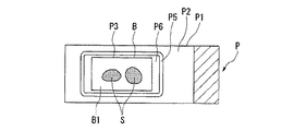
次に、図1に示すように、接着用水供給工程として、保持範囲P6内に接着用水Wを供給する。すなわち、制御部6は、まず、ハンドリングロボット7によって、保持枠P5が形成されたスライドガラスP1を、保持範囲P6が接着用水供給手段17の下方に位置するように移動させる。次に、接着用水供給手段17から、接着用水WをスライドガラスP1の保持範囲P6に所定量滴下させる。なお、供給する接着用水Wの量は、保持範囲P6の面積と、保持範囲P6に保持させる接着用水Wの所望の厚さによって決定される。ここで、保持範囲P6を囲む保持枠P5は、疎水性の材質で形成されているので、保持範囲P6に滴下された接着用水Wは、自己の表面張力による作用とともに、保持枠P5によって保持範囲P6外に流動するのが規制される。このため、接着用水Wは、保持枠P5より内側の保持範囲P6に所望の厚さを有して確実に保持された状態となる。
Next, as shown in FIG. 1, as a bonding water supply step, bonding water W is supplied into the holding range P6. That is, the control unit 6 first moves the slide glass P <b> 1 on which the holding frame P <b> 5 is formed by the handling robot 7 so that the holding range P <b> 6 is positioned below the bonding
次に、薄切片載置工程として、スライドガラスP1の載置範囲P3に薄切片Bを載置する。すなわち、図1に示すように、制御部6は、ハンドリングロボット7によって、接着水Wを有するスライドガラスP1を、載置台4の載置面4a上に載置する。また、載置台4のスライドガラスXステージ4b及びスライドガラス回転ステージ4cを駆動して、スライドガラスP1の位置及び向きについて微調整を行う。次に、搬送手段5によって薄切片BをスライドガラスP1まで搬送させる。図示しない包埋ブロックから作製された薄切片Bは、搬送手段5において、搬送テープ11の下面11bに静電気によって付着して保持されている。そして、制御部6が第一の駆動ローラ12a及び第二の駆動ローラ13aを協働して回転させることで、薄切片Bは搬送テープ11とともにX軸方向に沿って載置台4の上方に位置するまで移動する。次に、制御部6は、第二の駆動ローラ13aのみ回転方向を反転させることで、搬送テープ11を弛ませて、下面11bをスライドガラスP1の表面P2に当接させる。これにより、図4に示すように、搬送テープ11の下面11bに付着している薄切片Bは、保持範囲P6に保持されている接着用水Wに浸漬し、接着用水Wの表面張力によって搬送テープ11から離脱して載置範囲P3に載置された状態となる。ここで、上記のように保持範囲P6に所望の厚さで接着用水Wを保持することができることから、確実に搬送テープ11からスライドガラスP1上に薄切片Bを受け渡すことができ、また、気泡を巻き込むことを防ぐことができる。また、接着用水Wは保持枠P5によって流動することが規制されていることから、受け渡し後に薄切片B5が接着用水Wとともに移動し、あるいは、スライドガラスP1上から流出してしまうことが無く、薄切片Bを載置範囲P3で確実に保持することができる。
Next, as a thin slice placement step, the thin slice B is placed in the placement range P3 of the slide glass P1. That is, as shown in FIG. 1, the control unit 6 places the slide glass P <b> 1 having the adhesive water W on the
次に、お湯伸展工程として、スライドガラスP1の載置範囲P3に載置された薄切片Bのお湯伸展を行う。すなわち、制御部6は、ハンドリングロボット7によって、薄切片Bが載置されたスライドガラスP1を、再び加熱装置15の上面15a上に配置させる。なお、枠材供給部16は上方に退避した状態にある。この状態で、加熱装置15のヒータ15bを駆動し、スライドガラスP1を裏面P4から加熱すれば、接着用水Wは昇温して蒸発し、また、薄切片Bは伸展してスライドガラスP1の表面P2に付着した状態となり、図5に示すように、薄切片標本Pが作製される。ここで、上記のように薄切片Bを載置する際に気泡を巻き込むことを防ぐことができるので、本工程後に気泡によってスライドガラスP1と薄切片Bとの間に隙間が生じ、これに起因して皺が形成されてしまうのを防ぐことができる。最後に、収納工程として、制御部6は、ハンドリングロボット7によって、薄切片標本Pを薄切片標本保管庫3まで搬送して収納する。
Next, as a hot water extension step, hot water extension of the thin section B placed in the placement range P3 of the slide glass P1 is performed. That is, the control unit 6 causes the handling robot 7 to place the slide glass P1 on which the thin section B is placed on the
以上のように、本実施形態の薄切片標本作製装置1では、保持枠形成手段18によってスライドガラスP1上に保持枠P5を形成することで、保持枠P5で形成された保持範囲P6に接着用水Wを確実に保持し、スライドガラスP1と薄切片Bとの間に気泡が発生してしまうこと無く、確実に薄切片BをスライドガラスP1上に載置することができる。このため、歩留まり良く、薄切片Bに皺が無い一定の品質を有した薄切片標本Pを作製することができる。また、薄切片標本作製装置1では、保持枠形成手段18によって形成される保持枠P5を、包埋剤B1と同質のパラフィンで形成している。このため、作製された薄切片標本Pにおいて、さらに薄切片Bの包埋剤B1をキシレンによって溶解して置き換える際に、保持枠P5も同時に溶解させることができる。このため、包埋剤B1を置換えした後、生体試料Sを染色させる工程の際に保持枠P5が染色作業の支障となってしまうことがなく、染色後には、スライドガラスP1上の染色された生体試料Sを好適に観察することができる。なお、保持枠P5を形成する材料としては、包埋剤B1と同質の材料に限るものでは無い。少なくとも、疎水性を有する材料であれば、保持枠P5として機能することができる。また、パラフィンに限らず、キシレンによって溶解する材料であれば、染色させる工程において支障となってしまうことが無く、また、キシレンによって溶解しない材料としても、染色する工程において染色液によって溶解してしまうもので無ければ良い。
As described above, in the thin-section sample preparation device 1 of the present embodiment, the holding frame P5 is formed on the slide glass P1 by the holding
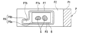
また、上記においては、保持枠P5は、矩形略枠状に形成されるものとしたが、これに限るものでは無く、少なくとも薄切片Bが載置される載置範囲P3を含むように保持範囲P6が形成されていれば良い。図6は、保持枠形成手段によって形成される保持枠の変形例を示している。図6に示すように、スライドガラスP1の表面P2上に形成される保持枠P7は、同様に略枠状で、略矩形の本体部P7aと、本体部P7aの一部から外側に突出した凸部P7bとを備える。このため、保持枠P7によって内側に形成される保持範囲P8は、本体部P7aで形成される保持部P8aと、凸部P7bで形成され本体部P7aから外側に突出した突出部P8bとで構成されることとなる。薄切片Bが載置される載置範囲P3は保持部P8aに含まれていて、突出部P8bは載置範囲P3の外側に突出することとなる。このため、載置範囲P3に薄切片Bを載置した状態で、薄切片Bの外側に保持範囲P8の一部である突出部P8bを露出させることができ、薄切片B載置後も、必要に応じて、突出部P8bから接着用水Wを供給、吸水し、接着用水Wの量をコントロールすることが可能となる。 In the above description, the holding frame P5 is formed in a substantially rectangular frame shape. However, the holding frame P5 is not limited to this, and the holding range includes at least the placement range P3 on which the thin section B is placed. P6 may be formed. FIG. 6 shows a modification of the holding frame formed by the holding frame forming means. As shown in FIG. 6, the holding frame P7 formed on the surface P2 of the slide glass P1 is similarly substantially frame-shaped, and has a substantially rectangular main body P7a and a protrusion protruding outward from a part of the main body P7a. Part P7b. For this reason, the holding range P8 formed inside by the holding frame P7 includes a holding part P8a formed by the main body part P7a and a protruding part P8b formed by the convex part P7b and protruding outward from the main body part P7a. The Rukoto. The placement range P3 on which the thin section B is placed is included in the holding portion P8a, and the protruding portion P8b protrudes outside the placement range P3. For this reason, in a state where the thin section B is placed in the placement range P3, the protruding portion P8b which is a part of the holding range P8 can be exposed outside the thin section B, and after the thin section B is placed, If necessary, it is possible to supply and absorb the bonding water W from the protruding portion P8b and control the amount of the bonding water W.
すなわち、図7に示すように、薄切片標本作製装置の構成として、保持範囲P8の突出部P8bから接着用水Wを吸水する吸水手段20を備えるものとする。より詳しくは、吸水手段20は、ポリウレタンなどで形成されたスポンジ状の吸水体21と、吸水体21を進退させる図示しない駆動手段とを備える。そして、薄切片載置工程として接着用水Wを有するスライドガラスP1の載置範囲P3に薄切片Bを載置した後に、吸水工程として、吸水手段20の吸水体21を駆動手段によって保持範囲P8の内の突出部P8bに当接させる。これにより、吸水手段20の吸水体21は、保持範囲P8において、突出部P8bに保持されている接着用水Wを吸水するとともに、保持部P8aの接着用水Wも突出部P8bへ誘導して、吸水することができ、薄切片BとスライドガラスP1との間に介装された接着用水Wを取り除くことができる。このため、薄切片載置工程では必要な接着用水Wを保持した状態で薄切片Bを載置することができる一方、薄切片載置工程後では薄切片Bに影響を与えず、余分な接着用水Wを除去することができる。
That is, as shown in FIG. 7, as a configuration of the thin-section specimen preparation device, it is assumed that a water absorption means 20 that absorbs the bonding water W from the protruding portion P8b of the holding range P8 is provided. More specifically, the
また、上記においては、保持枠形成工程において、保持枠形成手段によって、スライドガラスP1の表面P2上に、一つの保持枠を形成するものとしたが、これに限ること無い。例えば、図8に示すように、一つのスライドガラスP1上に、スライドガラスP1の長さ方向に三つの保持枠P7を配列させて形成するものとしても良い。このようにすることで、各保持枠P7によって、薄切片Bを載置可能な載置範囲P3を含む保持範囲P8を複数形成することができる。このため、一つのスライドガラスP1上に複数の薄切片Bを載置することができる。ここで、各載置範囲P3は、対応する保持枠P7によって囲まれていることで、載置された薄切片Bが隣接する載置範囲P3に移動してしまい、あるいは、隣接する載置範囲P3から異物が混入してしまうことを防ぐことができる。 In the above, in the holding frame forming step, one holding frame is formed on the surface P2 of the slide glass P1 by the holding frame forming means. However, the present invention is not limited to this. For example, as shown in FIG. 8, three holding frames P7 may be formed on one slide glass P1 in the length direction of the slide glass P1. By doing so, a plurality of holding ranges P8 including the mounting range P3 in which the thin slice B can be mounted can be formed by each holding frame P7. For this reason, a plurality of thin slices B can be placed on one slide glass P1. Here, each placement range P3 is surrounded by the corresponding holding frame P7, so that the placed thin section B moves to the adjacent placement range P3, or the adjacent placement range. It is possible to prevent foreign matters from being mixed in from P3.
以上、本発明の実施形態について図面を参照して詳述したが、具体的な構成はこの実施形態に限られるものではなく、本発明の要旨を逸脱しない範囲の設計変更等も含まれる。 As mentioned above, although embodiment of this invention was explained in full detail with reference to drawings, the concrete structure is not restricted to this embodiment, The design change etc. of the range which does not deviate from the summary of this invention are included.
なお、薄切片標本作製装置において、搬送手段5は、搬送テープ11を有し、静電気によって薄切片Bを付着させて搬送するものとしたが、これに限るものでは無い。搬送テープの表面に粘着性を有するものとして、粘着力によって薄切片Bを付着させて搬送するものとしても良い。また、搬送テープ上に載置させて搬送する方式としても良い。さらに、搬送テープによる搬送方式に限るものでは無く、薄切片を把持する方式などとしても良い。同様に、スライドガラスP1を搬送する手段であるハンドリングロボット7についてもこれに限るものでは無く、スライドガラスP1などの略板状のプレートを搬送可能なものであれば、公知の機構を適用することは可能である。また、保持枠形成手段18における加熱装置15と、伸展装置としての加熱装置15を兼用するものとして記載したが、これに限るものでは無く、別構成としても良い。また、保持枠形成手段18は、枠材供給部16をスライドガラスP1に当接させて加熱することで保持枠を形成するものとしたがこれに限るものでは無く、疎水性を有する材質を、保持枠を形成する範囲に塗布する方式などとしても良い。
In the thin-section sample preparation apparatus, the transport means 5 has the
1 薄切片作製装置
4 載置台
5 搬送手段
17 接着用水供給手段
18 保持枠形成手段
20 吸水手段
B 薄切片
B1 包埋剤
P 薄切片標本
P1 スライドガラス(プレート)
P2 表面
P3 載置範囲
P5、P7 保持枠
P6、P8 保持範囲
P8b 突出部
S 生体試料
W 接着用水
DESCRIPTION OF SYMBOLS 1 Thin
P2 surface P3 placement range P5, P7 holding frame P6, P8 holding range P8b protrusion S biological sample W water for bonding
Claims (10)
略枠状で疎水性の膜で形成された保持枠を、前記プレートの表面の内、少なくとも前記薄切片が載置される載置範囲を含む保持範囲を囲むように形成する保持枠形成手段と、
該保持範囲内に、接着用水を供給する接着用水供給手段と、
該接着用水を有した状態の前記プレートを載置する載置台と、
前記包埋ブロックから作製された前記薄切片を搬送し、前記載置台上に載置された前記プレートの前記載置範囲内に前記薄切片を載置する搬送手段とを備えることを特徴とする薄切片標本作製装置。 A thin-section specimen preparation device that prepares a thin-section specimen by placing a thin section prepared by cutting an embedding block in which a biological sample is embedded with an embedding agent at a predetermined thickness on a plate. There,
A holding frame forming means for forming a holding frame formed of a substantially frame-like and hydrophobic film so as to surround a holding range including at least a mounting range on which the thin slice is mounted on the surface of the plate; ,
An adhesive water supply means for supplying adhesive water within the holding range;
A mounting table for mounting the plate in a state having the bonding water;
The thin section prepared from the embedding block is transported, and transport means for placing the thin section within the placement range of the plate placed on the placement table is provided. Thin section specimen preparation device.
前記保持枠形成手段は、前記保持範囲として、前記載置範囲から外側に突出した突出部を有するように、前記保持枠の一部を突出して形成可能であることを特徴とする薄切片標本作製装置。 In the thin-section sample preparation apparatus according to claim 1,
The holding frame forming means is capable of forming a part of the holding frame so as to have a protruding portion protruding outward from the placement range as the holding range. apparatus.
前記保持範囲の前記突出部から露出する前記接着用水を吸水する吸水手段を備えることを特徴とする薄切片標本作製装置。 In the thin-section specimen preparation device according to claim 2,
An apparatus for preparing a thin-section specimen, comprising water-absorbing means for absorbing the bonding water exposed from the protruding portion of the holding range.
前記保持枠形成手段は、前記プレートの前記表面に前記保持枠を複数形成可能であることを特徴とする薄切片標本作製装置。 In the thin-section sample preparation device according to any one of claims 1 to 3,
The thin-section specimen preparation apparatus, wherein the holding frame forming means can form a plurality of the holding frames on the surface of the plate.
前記保持枠形成手段は、前記保持枠を、前記包埋剤によって形成することを特徴とする薄切片作製装置。 In the thin-section sample preparation device according to any one of claims 1 to 4,
The holding frame forming means forms the holding frame with the embedding agent.
略枠状で疎水性の膜で形成された保持枠を、前記プレートの表面の内、少なくとも前記薄切片が載置される載置範囲を含む保持範囲を囲むように形成する保持枠形成工程と、
該保持範囲内に、接着用水を供給する接着用水供給工程と、
該接着用水を有する前記プレートの前記載置範囲内に、前記薄切片を載置する薄切片載置工程とを備えることを特徴とする薄切片標本の作製方法。 A method for producing a thin slice specimen, in which a thin slice specimen prepared by cutting an embedded block in which a biological sample is embedded with an embedding agent at a predetermined thickness is placed on a plate Because
A holding frame forming step of forming a holding frame formed of a substantially frame-like and hydrophobic film so as to surround a holding range including at least a mounting range on which the thin slice is mounted on the surface of the plate; ,
An adhesive water supply step for supplying adhesive water within the holding range;
A thin-section specimen preparation method, comprising: a thin-section placement step of placing the thin-section within the placement range of the plate having the bonding water.
前記保持枠形成工程は、前記保持範囲として、前記載置範囲から外側に突出した突出部を有するように、前記保持枠の一部を突出させて形成することを特徴とする薄切片標本の作製方法。 The method for producing a thin-section specimen according to claim 6,
The holding frame forming step is characterized in that a part of the holding frame is protruded and formed so as to have a protruding portion protruding outward from the placement range as the holding range. Method.
前記薄切片載置工程後に、前記保持範囲の前記突出部から露出する前記接着用水を吸水する吸水工程を備えることを特徴とする薄切片標本の作製方法。 The method for producing a thin-section specimen according to claim 7,
A method for producing a thin-section specimen, comprising a water-absorbing step of absorbing the bonding water exposed from the protruding portion of the holding range after the thin-section placing step.
前記保持枠形成工程は、前記プレートの前記表面に前記保持枠を複数形成するとともに、
前記接着用水供給工程及び前記薄切片載置工程は、複数の前記保持枠で形成された前記保持範囲のそれぞれに、前記接着用水を供給し、前記薄切片を載置することを特徴とする薄切片標本の作製方法。 In the method for producing a thin-section sample according to any one of claims 6 to 8,
The holding frame forming step forms a plurality of the holding frames on the surface of the plate,
The bonding water supply step and the thin slice placement step supply the bonding water to each of the holding ranges formed by the plurality of holding frames, and place the thin slice. Method for preparing a section specimen.
前記保持枠形成工程は、前記保持枠を、前記包埋剤によって形成することを特徴とする薄切片標本の作製方法。 In the thin-section specimen preparation device according to any one of claims 6 to 9,
In the holding frame forming step, the holding frame is formed by the embedding agent.
Priority Applications (1)
| Application Number | Priority Date | Filing Date | Title |
|---|---|---|---|
| JP2006340187A JP4831486B2 (en) | 2006-12-18 | 2006-12-18 | Thin section specimen preparation device and thin section specimen preparation method |
Applications Claiming Priority (1)
| Application Number | Priority Date | Filing Date | Title |
|---|---|---|---|
| JP2006340187A JP4831486B2 (en) | 2006-12-18 | 2006-12-18 | Thin section specimen preparation device and thin section specimen preparation method |
Publications (2)
| Publication Number | Publication Date |
|---|---|
| JP2008151657A JP2008151657A (en) | 2008-07-03 |
| JP4831486B2 true JP4831486B2 (en) | 2011-12-07 |
Family
ID=39653969
Family Applications (1)
| Application Number | Title | Priority Date | Filing Date |
|---|---|---|---|
| JP2006340187A Active JP4831486B2 (en) | 2006-12-18 | 2006-12-18 | Thin section specimen preparation device and thin section specimen preparation method |
Country Status (1)
| Country | Link |
|---|---|
| JP (1) | JP4831486B2 (en) |
Cited By (1)
| Publication number | Priority date | Publication date | Assignee | Title |
|---|---|---|---|---|
| CN103502792A (en) * | 2011-03-02 | 2014-01-08 | 韩国地质资源研究院 | Method for preparing flake of unconsolidated sample and apparatus for solidifying unconsolidated sample used therein |
Families Citing this family (7)
| Publication number | Priority date | Publication date | Assignee | Title |
|---|---|---|---|---|
| EP2546628A1 (en) * | 2011-07-13 | 2013-01-16 | Koninklijke Philips Electronics N.V. | Filter support with a phase-changing medium |
| JP5995631B2 (en) * | 2012-09-28 | 2016-09-21 | シスメックス株式会社 | Specimen conveying apparatus, specimen inspection system, and specimen conveying method |
| CN110637221B (en) | 2017-07-19 | 2022-09-23 | 平田机工株式会社 | Specimen preparation method and specimen preparation device |
| JP7094398B2 (en) * | 2019-02-08 | 2022-07-01 | 平田機工株式会社 | Specimen preparation method |
| CN114341613B (en) * | 2019-09-04 | 2024-02-02 | 平田机工株式会社 | specimen preparation device |
| JP7236358B2 (en) | 2019-09-04 | 2023-03-09 | 平田機工株式会社 | Specimen preparation device |
| WO2026048163A1 (en) * | 2024-08-28 | 2026-03-05 | 株式会社日立ハイテク | Specimen sealing method and specimen sealing device |
Family Cites Families (4)
| Publication number | Priority date | Publication date | Assignee | Title |
|---|---|---|---|---|
| JP2004028910A (en) * | 2002-06-27 | 2004-01-29 | Toshiba Mach Co Ltd | Apparatus and method for preparing sliced sample |
| KR200327028Y1 (en) * | 2003-06-17 | 2003-09-19 | 장시창 | Tool for inspecting the tissue of human body |
| EP2492014A1 (en) * | 2003-09-09 | 2012-08-29 | BioGenex Laboratories | Sample processing system |
| JP2006300667A (en) * | 2005-04-19 | 2006-11-02 | Teiji Takezaki | Fixing and solidifying implement of embedding support agent, holding method of biological specimen and tissue arrayer gel |
-
2006
- 2006-12-18 JP JP2006340187A patent/JP4831486B2/en active Active
Cited By (2)
| Publication number | Priority date | Publication date | Assignee | Title |
|---|---|---|---|---|
| CN103502792A (en) * | 2011-03-02 | 2014-01-08 | 韩国地质资源研究院 | Method for preparing flake of unconsolidated sample and apparatus for solidifying unconsolidated sample used therein |
| CN103502792B (en) * | 2011-03-02 | 2016-06-08 | 韩国地质资源研究院 | Do not consolidate the method for producing sheet of sample and do not consolidate the solidification equipment of sample |
Also Published As
| Publication number | Publication date |
|---|---|
| JP2008151657A (en) | 2008-07-03 |
Similar Documents
| Publication | Publication Date | Title |
|---|---|---|
| US7966091B2 (en) | Automatic thin-section slides manufacturing system and method | |
| JP6013142B2 (en) | Thin section preparation equipment | |
| JP4607703B2 (en) | Thin section preparation method | |
| EP2246687A2 (en) | Thin-section slides manufacturing apparatus and method for manufacturing thin-section slides | |
| JP4674810B2 (en) | Automatic thin section specimen preparation device and automatic thin section specimen preparation method | |
| US8166855B2 (en) | Thin section preparing apparatus and thin section preparing method | |
| JP4831486B2 (en) | Thin section specimen preparation device and thin section specimen preparation method | |
| JP5827490B2 (en) | Thin section sample preparation equipment | |
| US11754473B2 (en) | Method and apparatus to manipulate biological sections | |
| WO2007094206A1 (en) | Automatic device for making slice piece specimen and automatic method for making slice piece specimen | |
| US20140255978A1 (en) | Tissue dividing apparatus, tissue dividing method, and cell collecting method | |
| CN104769408A (en) | Block material storage device and automatic thin cutting device | |
| JP2004028910A (en) | Apparatus and method for preparing sliced sample | |
| US20240118295A1 (en) | Apparatus and methods for transferring a tissue section | |
| JP5222541B2 (en) | Thin section preparation equipment | |
| JP2010266394A (en) | Thin slice preparation device | |
| CN104048861A (en) | Equipment for processing tissue samples | |
| JP2013088387A (en) | Sample preparation method and sample preparation device | |
| JP4795181B2 (en) | Sample block surface placement method | |
| JPH10104136A (en) | Method for preparing thin section sample for tissue observation | |
| JP5878986B2 (en) | Thin section manufacturing method and thin section manufacturing apparatus | |
| JP2009180546A (en) | Thin slice specimen preparation device and thin slice specimen preparation method | |
| CN104781645B (en) | Slice production method and slice producing device | |
| JP2008157835A (en) | Device and method for manufacturing thin sliced specimen | |
| JP2008145382A (en) | Preparing apparatus and method for thin-slice specimen |
Legal Events
| Date | Code | Title | Description |
|---|---|---|---|
| A621 | Written request for application examination |
Free format text: JAPANESE INTERMEDIATE CODE: A621 Effective date: 20090902 |
|
| A977 | Report on retrieval |
Free format text: JAPANESE INTERMEDIATE CODE: A971007 Effective date: 20110804 |
|
| TRDD | Decision of grant or rejection written | ||
| A01 | Written decision to grant a patent or to grant a registration (utility model) |
Free format text: JAPANESE INTERMEDIATE CODE: A01 Effective date: 20110830 |
|
| A01 | Written decision to grant a patent or to grant a registration (utility model) |
Free format text: JAPANESE INTERMEDIATE CODE: A01 |
|
| RD03 | Notification of appointment of power of attorney |
Free format text: JAPANESE INTERMEDIATE CODE: A7423 Effective date: 20110908 |
|
| A61 | First payment of annual fees (during grant procedure) |
Free format text: JAPANESE INTERMEDIATE CODE: A61 Effective date: 20110908 |
|
| R150 | Certificate of patent or registration of utility model |
Ref document number: 4831486 Country of ref document: JP Free format text: JAPANESE INTERMEDIATE CODE: R150 Free format text: JAPANESE INTERMEDIATE CODE: R150 |
|
| FPAY | Renewal fee payment (event date is renewal date of database) |
Free format text: PAYMENT UNTIL: 20140930 Year of fee payment: 3 |
|
| FPAY | Renewal fee payment (event date is renewal date of database) |
Free format text: PAYMENT UNTIL: 20140930 Year of fee payment: 3 |
|
| S111 | Request for change of ownership or part of ownership |
Free format text: JAPANESE INTERMEDIATE CODE: R313113 |
|
| FPAY | Renewal fee payment (event date is renewal date of database) |
Free format text: PAYMENT UNTIL: 20140930 Year of fee payment: 3 |
|
| R350 | Written notification of registration of transfer |
Free format text: JAPANESE INTERMEDIATE CODE: R350 |
|
| R250 | Receipt of annual fees |
Free format text: JAPANESE INTERMEDIATE CODE: R250 |
|
| R250 | Receipt of annual fees |
Free format text: JAPANESE INTERMEDIATE CODE: R250 |
|
| R250 | Receipt of annual fees |
Free format text: JAPANESE INTERMEDIATE CODE: R250 |
|
| R250 | Receipt of annual fees |
Free format text: JAPANESE INTERMEDIATE CODE: R250 |