JP4833672B2 - 固定部材、及び、取付構造 - Google Patents
固定部材、及び、取付構造 Download PDFInfo
- Publication number
- JP4833672B2 JP4833672B2 JP2006013922A JP2006013922A JP4833672B2 JP 4833672 B2 JP4833672 B2 JP 4833672B2 JP 2006013922 A JP2006013922 A JP 2006013922A JP 2006013922 A JP2006013922 A JP 2006013922A JP 4833672 B2 JP4833672 B2 JP 4833672B2
- Authority
- JP
- Japan
- Prior art keywords
- claw
- opening
- male connector
- guide
- fixing member
- Prior art date
- Legal status (The legal status is an assumption and is not a legal conclusion. Google has not performed a legal analysis and makes no representation as to the accuracy of the status listed.)
- Expired - Fee Related
Links
Images




Classifications
-
- H—ELECTRICITY
- H01—ELECTRIC ELEMENTS
- H01R—ELECTRICALLY-CONDUCTIVE CONNECTIONS; STRUCTURAL ASSOCIATIONS OF A PLURALITY OF MUTUALLY-INSULATED ELECTRICAL CONNECTING ELEMENTS; COUPLING DEVICES; CURRENT COLLECTORS
- H01R12/00—Structural associations of a plurality of mutually-insulated electrical connecting elements, specially adapted for printed circuits, e.g. printed circuit boards [PCB], flat or ribbon cables, or like generally planar structures, e.g. terminal strips, terminal blocks; Coupling devices specially adapted for printed circuits, flat or ribbon cables, or like generally planar structures; Terminals specially adapted for contact with, or insertion into, printed circuits, flat or ribbon cables, or like generally planar structures
- H01R12/70—Coupling devices
- H01R12/7005—Guiding, mounting, polarizing or locking means; Extractors
- H01R12/7011—Locking or fixing a connector to a PCB
- H01R12/7017—Snap means
Landscapes
- Coupling Device And Connection With Printed Circuit (AREA)
- Mounting Components In General For Electric Apparatus (AREA)
Description
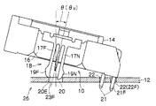
まず、第1実施形態について説明する。図1に示すように、本実施形態の固定部材10は、プリント配線基板12に固定される電子部品14に取付け可能な部材である。
次に、第2実施形態について説明する。本実施形態の固定部材では、第1実施形態に比べ、2本のアーム部17F、17Nに代えて、図3に示すような2本のアーム部37F、37Nが設けられた雄コネクタ部38が設けられている。
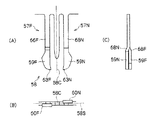
次に、第3実施形態について説明する。本実施形態の固定部材では、第1実施形態に比べ、2本のアーム部17F、17Nに代えて、図6に示すような2本のアーム部57F、57Nが設けられた雄コネクタ部58が設けられている。
12 プリント配線基板
14 電子部品(被固定部材)
17F、N アーム部
18 雄コネクタ部
19F、N 爪部
20 開口(差込用開口)
20E 開口縁
21 端子
21F 端子
22 挿通孔
23F、N 爪部案内部
26 取付構造
37F、N アーム部
38 雄コネクタ部
39F、N 爪部
43F、N 爪部案内部
57F、N アーム部
58 雄コネクタ部
59F、N 爪部
63F、N 爪部案内部
84 電子部品
82 プリント配線基板
80 固定部材
87F、N アーム部
88 雄コネクタ部
90 開口(差込用開口)
90E 開口縁
99F、N 爪部
Claims (3)
- プリント配線基板に固定される被固定部材に取付け可能で、前記被固定部材を前記プリント配線基板に固定するのに用いられる固定部材であって、
前記プリント配線基板に形成された差込用開口に挿入される雄コネクタ部を備え、
前記雄コネクタ部には2本のアーム部が同一面上に設けられ、
前記アーム部の先端側には、それぞれ、前記開口の開口縁で係止される突出部が突出して設けられた爪部が設けられており、
前記爪部の先端部では、それぞれ、前記開口縁に当接して更に押圧されると前記爪部を前記差込用開口へ案内する爪部案内部が前記爪部の基端部に対し前記突出部とは反対側へ延び出すと共に、前記爪部案内部が前記開口縁に当接して前記爪部を前記差込用開口へ案内したときに、前記爪部案内部同士が互いに非干渉となっていることを特徴とする固定部材。 - 請求項1に記載の固定部材が請求項1に記載の被固定部材に取付けられ、
前記被固定部材には、前記プリント配線基板に形成されている挿通孔に挿入される端子が突出しており、
前記端子を前記挿通孔に挿入可能な深さにまで挿入し、更に、前記雄コネクタ部を前記差込用開口に向けて押圧すると、前記爪部案内部が前記開口縁に当接して前記爪部が前記差込用開口に挿入されていくように、前記爪部案内部の寸法が決められていることを特徴とする取付構造。 - 前記端子が前記挿通孔に挿入され、かつ、前記爪部が前記開口縁に当接したときの前記開口の法線方向に対する前記雄コネクタ部の傾斜角度に基づいて、前記爪部案内部の寸法が決められていることを特徴とする請求項2に記載の取付構造。
Priority Applications (3)
| Application Number | Priority Date | Filing Date | Title |
|---|---|---|---|
| JP2006013922A JP4833672B2 (ja) | 2006-01-23 | 2006-01-23 | 固定部材、及び、取付構造 |
| US11/623,037 US7320619B2 (en) | 2006-01-23 | 2007-01-12 | Fixing member and mounting structure |
| CNB200710004344XA CN100479261C (zh) | 2006-01-23 | 2007-01-23 | 固定部件和安装结构 |
Applications Claiming Priority (1)
| Application Number | Priority Date | Filing Date | Title |
|---|---|---|---|
| JP2006013922A JP4833672B2 (ja) | 2006-01-23 | 2006-01-23 | 固定部材、及び、取付構造 |
Publications (2)
| Publication Number | Publication Date |
|---|---|
| JP2007200557A JP2007200557A (ja) | 2007-08-09 |
| JP4833672B2 true JP4833672B2 (ja) | 2011-12-07 |
Family
ID=38286125
Family Applications (1)
| Application Number | Title | Priority Date | Filing Date |
|---|---|---|---|
| JP2006013922A Expired - Fee Related JP4833672B2 (ja) | 2006-01-23 | 2006-01-23 | 固定部材、及び、取付構造 |
Country Status (3)
| Country | Link |
|---|---|
| US (1) | US7320619B2 (ja) |
| JP (1) | JP4833672B2 (ja) |
| CN (1) | CN100479261C (ja) |
Families Citing this family (17)
| Publication number | Priority date | Publication date | Assignee | Title |
|---|---|---|---|---|
| JP2007128772A (ja) * | 2005-11-04 | 2007-05-24 | Tyco Electronics Amp Kk | 保持部材、実装構造、および電子部品 |
| US8871694B2 (en) * | 2005-12-09 | 2014-10-28 | Sarkis R. Kakadjian | Use of zeta potential modifiers to decrease the residual oil saturation |
| JP4626680B2 (ja) * | 2008-06-25 | 2011-02-09 | 株式会社デンソー | 保持部材、電子部品、及び電子装置 |
| EP2091106B1 (en) * | 2008-01-17 | 2013-10-02 | Denso Corporation | Retaining member, electric component and electric device |
| JP4591514B2 (ja) * | 2008-01-17 | 2010-12-01 | 株式会社デンソー | 保持部材、電子部品、及び電子装置 |
| JP5202973B2 (ja) * | 2008-01-30 | 2013-06-05 | タイコエレクトロニクスジャパン合同会社 | 保持部材、保持部材が電気回路基板に実装された実装構造、および保持部材を備えた電子部品 |
| US8123572B2 (en) * | 2010-04-02 | 2012-02-28 | Tyco Electronics Corporation | Electrical components having a contact configured to engage a via of a circuit board |
| FR2979036B1 (fr) * | 2011-08-08 | 2014-05-02 | Valeo Sys Controle Moteur Sas | Dispositif de connexion electrique, ensemble comprenant un tel dispositif et une carte electronique et procede de connexion electrique d'une carte electronique |
| US10485117B2 (en) * | 2014-10-28 | 2019-11-19 | Sumitomo Wiring Systems, Ltd. | Electrical junction box |
| US10186892B2 (en) | 2015-12-24 | 2019-01-22 | Energous Corporation | Receiver device with antennas positioned in gaps |
| US10038332B1 (en) | 2015-12-24 | 2018-07-31 | Energous Corporation | Systems and methods of wireless power charging through multiple receiving devices |
| US10003144B1 (en) * | 2016-12-20 | 2018-06-19 | Te Connectivity Corporation | Electrical connector assembly and conductive assembly having an intervening wall |
| WO2018163247A1 (ja) * | 2017-03-06 | 2018-09-13 | 三菱電機株式会社 | プレスフィット構造を有する制御ユニット |
| JP6617119B2 (ja) * | 2017-06-21 | 2019-12-04 | 矢崎総業株式会社 | 電子部品ユニット、ワイヤハーネス、及び、コネクタ固定構造 |
| KR102345677B1 (ko) * | 2018-05-08 | 2021-12-29 | 주식회사 엘지에너지솔루션 | 수직 타입의 다이렉트 pcb 커넥터 |
| CN114630542B (zh) * | 2020-12-14 | 2023-10-13 | 光宝电子(广州)有限公司 | 固定组件及板对板固定装置 |
| JP7482021B2 (ja) | 2020-12-25 | 2024-05-13 | 日本航空電子工業株式会社 | 電気部品 |
Family Cites Families (18)
| Publication number | Priority date | Publication date | Assignee | Title |
|---|---|---|---|---|
| JPS54137789A (en) * | 1978-04-18 | 1979-10-25 | Noritake Dia Kk | Segment type grindstone for surface grinding |
| JPH0218527Y2 (ja) * | 1985-04-04 | 1990-05-23 | ||
| JPH0212169A (ja) * | 1988-06-30 | 1990-01-17 | Canon Inc | 画像形成装置 |
| JPH0340793U (ja) * | 1989-08-31 | 1991-04-18 | ||
| US5257948A (en) * | 1992-12-14 | 1993-11-02 | Molex Incorporated | Printed circuit board mounting device for electrical connectors |
| US5409399A (en) * | 1993-12-08 | 1995-04-25 | Molex Incorporated | Electrical connection assembly for mounting on a printed circuit board |
| US5489219A (en) * | 1994-05-24 | 1996-02-06 | The Whitaker Corporation | Self-retaining board lock |
| US5664965A (en) * | 1996-03-29 | 1997-09-09 | Berg Technology, Inc. | Device for fixing an electrical connector to a printed circuit board |
| JPH09330753A (ja) | 1996-06-10 | 1997-12-22 | Matsushita Electric Ind Co Ltd | 接続端子 |
| TW385924U (en) * | 1996-12-21 | 2000-03-21 | Hon Hai Prec Ind Co Ltd | Fastener apparatus for substrate of electric connector |
| US5868587A (en) * | 1997-02-20 | 1999-02-09 | The Whitaker Corporation | Component mounting device |
| US5957722A (en) * | 1997-08-27 | 1999-09-28 | Hon Hai Precision Ind. Co., Ltd. | Locking device for an electrical connector |
| JPH11111407A (ja) | 1997-10-03 | 1999-04-23 | Fujitsu Ltd | コネクタの表面実装方法およびコネクタ |
| JP2002216878A (ja) * | 2001-01-23 | 2002-08-02 | Yazaki Corp | 基板用コネクタの取付け方法及び基板用コネクタ |
| US6638105B1 (en) * | 2002-07-31 | 2003-10-28 | Hon Hai Precision Ind. Co., Ltd. | Self-retaining board lock for electrical connector |
| US6565383B1 (en) * | 2002-09-11 | 2003-05-20 | Hon Hai Precision Ind. Co., Ltd. | Electrical connector with locking member |
| JP4007970B2 (ja) * | 2004-03-30 | 2007-11-14 | 日本航空電子工業株式会社 | コネクタ固定部材とそれを用いたコネクタ |
| US7172457B1 (en) * | 2006-04-21 | 2007-02-06 | Lotes Co., Ltd. | Locking device |
-
2006
- 2006-01-23 JP JP2006013922A patent/JP4833672B2/ja not_active Expired - Fee Related
-
2007
- 2007-01-12 US US11/623,037 patent/US7320619B2/en active Active
- 2007-01-23 CN CNB200710004344XA patent/CN100479261C/zh not_active Expired - Fee Related
Also Published As
| Publication number | Publication date |
|---|---|
| CN100479261C (zh) | 2009-04-15 |
| US7320619B2 (en) | 2008-01-22 |
| CN101009407A (zh) | 2007-08-01 |
| JP2007200557A (ja) | 2007-08-09 |
| US20070173114A1 (en) | 2007-07-26 |
Similar Documents
| Publication | Publication Date | Title |
|---|---|---|
| JP2007200557A (ja) | 固定部材、及び、取付構造 | |
| CN112092765B (zh) | 紧固夹 | |
| CN102292874B (zh) | 板对板连接器 | |
| JP6101435B2 (ja) | コネクタ | |
| JP5742741B2 (ja) | 端子 | |
| US8434727B2 (en) | Fixing bracket, fixing method of fixing bracket and fixing structure of fixing bracket | |
| US20110111614A1 (en) | Card edge connector | |
| KR20110139092A (ko) | 커넥터 | |
| US7500872B2 (en) | Connector | |
| US20070173134A1 (en) | Fixing member and fixing structure | |
| TW202121778A (zh) | 插座及工具 | |
| JP2012142146A (ja) | カードエッジコネクタ | |
| JP2008300371A (ja) | ロック機能付き補強金具及びそれを備えたコネクタ | |
| TWI532265B (zh) | 連接端子及使用該連接端子的連接器 | |
| JP4195438B2 (ja) | コネクタ | |
| JP4802059B2 (ja) | 電気部品用ソケット | |
| JP2012199190A (ja) | コネクタ | |
| JP2006127873A (ja) | コネクタ固定用金具 | |
| JP2006197659A (ja) | ワイヤハーネス用プロテクタ | |
| JP6491692B2 (ja) | 回路基板収容筐体、および電子装置 | |
| US7704090B2 (en) | Housing for a card edge connector assembly | |
| KR200431623Y1 (ko) | 기판 연결용 커넥터 | |
| JP4809385B2 (ja) | プリント基板 | |
| KR101319548B1 (ko) | 인쇄회로기판의 휨방지장치 | |
| JP2004342363A (ja) | コネクタ及びその圧入用治具 |
Legal Events
| Date | Code | Title | Description |
|---|---|---|---|
| A621 | Written request for application examination |
Free format text: JAPANESE INTERMEDIATE CODE: A621 Effective date: 20080523 |
|
| A977 | Report on retrieval |
Free format text: JAPANESE INTERMEDIATE CODE: A971007 Effective date: 20100615 |
|
| A131 | Notification of reasons for refusal |
Free format text: JAPANESE INTERMEDIATE CODE: A131 Effective date: 20100622 |
|
| A521 | Written amendment |
Free format text: JAPANESE INTERMEDIATE CODE: A523 Effective date: 20100802 |
|
| A131 | Notification of reasons for refusal |
Free format text: JAPANESE INTERMEDIATE CODE: A131 Effective date: 20110125 |
|
| TRDD | Decision of grant or rejection written | ||
| A01 | Written decision to grant a patent or to grant a registration (utility model) |
Free format text: JAPANESE INTERMEDIATE CODE: A01 Effective date: 20110920 |
|
| A01 | Written decision to grant a patent or to grant a registration (utility model) |
Free format text: JAPANESE INTERMEDIATE CODE: A01 |
|
| A61 | First payment of annual fees (during grant procedure) |
Free format text: JAPANESE INTERMEDIATE CODE: A61 Effective date: 20110922 |
|
| R150 | Certificate of patent or registration of utility model |
Ref document number: 4833672 Country of ref document: JP Free format text: JAPANESE INTERMEDIATE CODE: R150 Free format text: JAPANESE INTERMEDIATE CODE: R150 |
|
| FPAY | Renewal fee payment (event date is renewal date of database) |
Free format text: PAYMENT UNTIL: 20140930 Year of fee payment: 3 |
|
| R250 | Receipt of annual fees |
Free format text: JAPANESE INTERMEDIATE CODE: R250 |
|
| R250 | Receipt of annual fees |
Free format text: JAPANESE INTERMEDIATE CODE: R250 |
|
| R250 | Receipt of annual fees |
Free format text: JAPANESE INTERMEDIATE CODE: R250 |
|
| R250 | Receipt of annual fees |
Free format text: JAPANESE INTERMEDIATE CODE: R250 |
|
| R250 | Receipt of annual fees |
Free format text: JAPANESE INTERMEDIATE CODE: R250 |
|
| R250 | Receipt of annual fees |
Free format text: JAPANESE INTERMEDIATE CODE: R250 |
|
| LAPS | Cancellation because of no payment of annual fees |