JP4865740B2 - Rush adjuster - Google Patents
Rush adjuster Download PDFInfo
- Publication number
- JP4865740B2 JP4865740B2 JP2008019066A JP2008019066A JP4865740B2 JP 4865740 B2 JP4865740 B2 JP 4865740B2 JP 2008019066 A JP2008019066 A JP 2008019066A JP 2008019066 A JP2008019066 A JP 2008019066A JP 4865740 B2 JP4865740 B2 JP 4865740B2
- Authority
- JP
- Japan
- Prior art keywords
- plunger
- ring
- shaped member
- peripheral surface
- pressure chamber
- Prior art date
- Legal status (The legal status is an assumption and is not a legal conclusion. Google has not performed a legal analysis and makes no representation as to the accuracy of the status listed.)
- Expired - Fee Related
Links
- 230000002093 peripheral effect Effects 0.000 claims description 46
- 239000010720 hydraulic oil Substances 0.000 claims description 36
- 239000012530 fluid Substances 0.000 claims description 4
- 230000002159 abnormal effect Effects 0.000 description 3
- 238000002485 combustion reaction Methods 0.000 description 2
- 230000005489 elastic deformation Effects 0.000 description 2
- 229920003002 synthetic resin Polymers 0.000 description 2
- 239000000057 synthetic resin Substances 0.000 description 2
- 230000002238 attenuated effect Effects 0.000 description 1
- 230000006835 compression Effects 0.000 description 1
- 238000007906 compression Methods 0.000 description 1
- 238000013016 damping Methods 0.000 description 1
- 230000007423 decrease Effects 0.000 description 1
- 238000006073 displacement reaction Methods 0.000 description 1
- 230000000694 effects Effects 0.000 description 1
- 239000013013 elastic material Substances 0.000 description 1
- 230000009969 flowable effect Effects 0.000 description 1
- 239000002184 metal Substances 0.000 description 1
- 239000003921 oil Substances 0.000 description 1
- 230000000149 penetrating effect Effects 0.000 description 1
- 238000009751 slip forming Methods 0.000 description 1
Images




Classifications
-
- F—MECHANICAL ENGINEERING; LIGHTING; HEATING; WEAPONS; BLASTING
- F01—MACHINES OR ENGINES IN GENERAL; ENGINE PLANTS IN GENERAL; STEAM ENGINES
- F01L—CYCLICALLY OPERATING VALVES FOR MACHINES OR ENGINES
- F01L1/00—Valve-gear or valve arrangements, e.g. lift-valve gear
- F01L1/20—Adjusting or compensating clearance
- F01L1/22—Adjusting or compensating clearance automatically, e.g. mechanically
- F01L1/24—Adjusting or compensating clearance automatically, e.g. mechanically by fluid means, e.g. hydraulically
-
- F—MECHANICAL ENGINEERING; LIGHTING; HEATING; WEAPONS; BLASTING
- F01—MACHINES OR ENGINES IN GENERAL; ENGINE PLANTS IN GENERAL; STEAM ENGINES
- F01L—CYCLICALLY OPERATING VALVES FOR MACHINES OR ENGINES
- F01L1/00—Valve-gear or valve arrangements, e.g. lift-valve gear
- F01L1/20—Adjusting or compensating clearance
- F01L1/22—Adjusting or compensating clearance automatically, e.g. mechanically
- F01L1/24—Adjusting or compensating clearance automatically, e.g. mechanically by fluid means, e.g. hydraulically
- F01L1/2405—Adjusting or compensating clearance automatically, e.g. mechanically by fluid means, e.g. hydraulically by means of a hydraulic adjusting device located between the cylinder head and rocker arm
Landscapes
- Engineering & Computer Science (AREA)
- Mechanical Engineering (AREA)
- General Engineering & Computer Science (AREA)
- Valve-Gear Or Valve Arrangements (AREA)
Abstract
Description
本発明は、内燃機関の動弁装置に用いられる油圧式のラッシュアジャスタに関するものである。 The present invention relates to a hydraulic lash adjuster used in a valve gear for an internal combustion engine.
特許文献1には、有底筒状のボディと、ボディ内に昇降可能に設けられた有底筒状のプランジャとを備え、ボディの下端部にはプランジャの底壁部で区画された高圧室が形成され、プランジャが下降するときには、高圧室内の作動油がボディの内周とプランジャの外周との隙間を通ってリークするようになっているラッシュアジャスタが開示されている。 Patent Document 1 includes a bottomed cylindrical body and a bottomed cylindrical plunger provided in the body so as to be movable up and down, and a high pressure chamber defined by a bottom wall portion of the plunger at a lower end portion of the body. When the plunger is lowered, the lash adjuster is disclosed in which the hydraulic oil in the high pressure chamber leaks through the gap between the inner periphery of the body and the outer periphery of the plunger.
プランジャの上端部にはロッカアームの揺動支点となる基端部が載置され、ロッカアームの自由端部はバルブステムの上端を押さえ付けている。ロッカアームは、その上面に摺接するカムの回転に伴って上下に揺動し、ロッカアームの上動によりバルブが閉弁され、ロッカアームの可動によりバルブが開弁される。
動弁装置において異常運動が発生すると、それが原因となってプランジャが正常な昇降域を超えて過剰に上昇することがある。この場合、ロッカアームの揺動支点が高くなるため、ロッカアームにカムのカムベース部が摺接してロッカアームが最上位置に達した状態になっても、バルブが閉弁しなくなる。 When abnormal motion occurs in the valve operating device, the plunger may rise excessively beyond the normal lift area due to this. In this case, since the rocking fulcrum of the rocker arm becomes high, even if the cam base portion of the cam slides on the rocker arm and the rocker arm reaches the uppermost position, the valve does not close.
これを回避するためには、プランジャを速やかに下降させる必要があるが、従来のラッシュアジャスタでは、プランジャの下降に伴って高圧室内の作動油をリークさせる経路は、プランジャの外周とボディの内周との間の狭い隙間によって構成されているので、この狭いリーク経路を通過するときの流動抵抗は大きい。開弁時には、バルブを閉弁方向に付勢しているバルブスプリングの弾性復元力が増大するため、ロッカアームからプランジャに作用する荷重も大きくなるのであるが、このような大きな荷重を受けても、リーク経路の流動抵抗は大きいので、プランジャを速やかに下降させることはできない。 In order to avoid this, it is necessary to lower the plunger quickly. However, in the conventional lash adjuster, the path for leaking the hydraulic oil in the high pressure chamber as the plunger is lowered is the outer periphery of the plunger and the inner periphery of the body. The flow resistance when passing through this narrow leak path is large. When the valve is opened, the elastic restoring force of the valve spring urging the valve in the valve closing direction increases, so the load acting on the plunger from the rocker arm also increases. Since the flow resistance of the leak path is large, the plunger cannot be lowered quickly.
尚、プランジャの下降速度を速める手段としては、プランジャの外径とボディの内径との寸法差を大きくしてリーク流路の断面積を拡大し、作動油の流動抵抗を低減することが考えられる。しかし、このリーク流路は、動弁装置及びラッシュアジャスタが正常に作動している状態において、ロッカアームからプランジャに作用する荷重を減衰してプランジャの下降動作を抑制する手段として機能するものであることから、リーク経路を単に広げることはできない。
本発明は上記のような事情に基づいて完成されたものであって、正常な昇降域を超えて過剰に上昇したプランジャを速やかに下降させることができるようにすることを目的とする。
As a means for increasing the descending speed of the plunger, it is conceivable to increase the dimensional difference between the outer diameter of the plunger and the inner diameter of the body to enlarge the cross-sectional area of the leak flow path and reduce the hydraulic fluid flow resistance. . However, this leak flow path functions as a means for attenuating the load acting on the plunger from the rocker arm and suppressing the downward movement of the plunger when the valve gear and the lash adjuster are operating normally. Therefore, it is not possible to simply widen the leak path.
The present invention has been completed based on the above situation, and an object of the present invention is to enable a plunger that has been excessively raised beyond a normal lifting area to be quickly lowered.
上記の目的を達成するための手段として、請求項1の発明は、有底筒状のボディと、前記ボディ内に昇降可能に設けられた有底筒状のプランジャとを備え、前記ボディの下端部には前記プランジャの底壁部で区画された高圧室が形成され、前記プランジャが下降するときには、前記高圧室内の作動油が前記ボディの内周面と前記プランジャの外周面との間のリーク経路を通ってリークするようになっているラッシュアジャスタにおいて、前記ボディの内周面と前記プランジャの外周面との間には、常には前記リーク流路内に進出する状態を保ち、前記高圧室側からの作動油の圧力の増大により前記リーク流路から退避するように径方向に弾性変形して前記リーク経路内における作動油の流動抵抗を低減させるリング状部材が設けられているところに特徴を有する。 As means for achieving the above object, the invention of claim 1 includes a bottomed cylindrical body and a bottomed cylindrical plunger provided in the body so as to be movable up and down, and a lower end of the body. A high pressure chamber defined by the bottom wall portion of the plunger is formed in the portion, and when the plunger descends, hydraulic oil in the high pressure chamber leaks between the inner peripheral surface of the body and the outer peripheral surface of the plunger. In the lash adjuster configured to leak through the path, the high pressure chamber is always maintained between the inner peripheral surface of the body and the outer peripheral surface of the plunger. A ring-shaped member is provided that is elastically deformed in a radial direction so as to retreat from the leak flow path due to an increase in hydraulic oil pressure from the side, and reduces the flow resistance of the hydraulic oil in the leak path. Furnace has a feature.
請求項2の発明は、請求項1に記載のものにおいて、前記リング状部材には、径方向に対して傾斜した形態であって前記高圧室側からの作動油の圧力を受けることが可能な受圧面が形成されているところに特徴を有する。 According to a second aspect of the present invention, in the first aspect, the ring-shaped member is inclined with respect to the radial direction and can receive the pressure of the hydraulic oil from the high pressure chamber side. It is characterized in that the pressure receiving surface is formed.
請求項3の発明は、請求項1または請求項2に記載のものにおいて、前記リング状部材は、前記ボディの内周面又は前記プランジャの外周面のうち一方の周面に形成した保持溝内に収容されており、前記リング状部材の径方向の変形量が最大となった状態において、前記保持溝の溝底面と前記リング状部材の周面との間に径方向のクリアランスが確保されるようになっているところに特徴を有する。 According to a third aspect of the present invention, in the first or second aspect of the present invention, the ring-shaped member is in a holding groove formed on one of the inner peripheral surface of the body or the outer peripheral surface of the plunger. In the state where the amount of deformation in the radial direction of the ring-shaped member is maximized, a radial clearance is ensured between the groove bottom surface of the holding groove and the peripheral surface of the ring-shaped member. It has the characteristics in the place.
請求項4の発明は、請求項1ないし請求項3のいずれかに記載のものにおいて、前記リング状部材に、作動油の流動を許容する連通部が形成されているところに特徴を有する。 The invention according to claim 4 is characterized in that, in the invention according to any one of claims 1 to 3, the ring-shaped member is formed with a communicating portion that allows the flow of hydraulic oil.
<請求項1の発明>
プランジャに対して作用する下降方向の力が正常の範囲内である場合は、リング状部材がリーク経路内に進出してリーク経路が絞られるので、リーク経路における作動油の流動抵抗は比較的大きく、プランジャが急速に下降することはない。これに対し、プランジャに作用する下降方向の力が増大すると、高圧室側からリング状部材に作用する作動油の圧力が増大するので、リング状部材がリーク経路から退避するように径方向に弾性変形し、リーク経路内における作動油の流動抵抗が低減される。これにより、プランジャが速やかに下降する。
<Invention of Claim 1>
When the downward force acting on the plunger is within the normal range, the ring-shaped member advances into the leak path and the leak path is narrowed, so the hydraulic fluid flow resistance in the leak path is relatively large. The plunger does not descend rapidly. On the other hand, if the downward force acting on the plunger increases, the pressure of the hydraulic oil acting on the ring-shaped member from the high-pressure chamber side increases, so that the ring-shaped member is elastic in the radial direction so as to retreat from the leak path. It deforms and the flow resistance of the hydraulic oil in the leak path is reduced. Thereby, the plunger descends quickly.
<請求項2の発明>
高圧室側からの作動油の圧力が作用する受圧面は、リング状部材の変形方向である径方向に対して傾斜しているので、作動油から受圧面に作用する圧力によってリング状部材には径方向の押圧力が付与されることになる。したがって、リング状部材は確実に径方向に変形することができる。
<Invention of Claim 2>
Since the pressure receiving surface on which the hydraulic oil pressure from the high pressure chamber side acts is inclined with respect to the radial direction, which is the deformation direction of the ring-shaped member, the ring-shaped member has a pressure acting on the pressure receiving surface from the hydraulic oil. A radial pressing force is applied. Therefore, the ring-shaped member can be reliably deformed in the radial direction.
<請求項3の発明>
プランジャがボディに対して径方向に偏心するように位置ずれした場合には、保持溝の溝底面とリング状部材の周面との間に径方向のクリアランスによって位置ずれが吸収される。
<Invention of Claim 3>
When the plunger is displaced so as to be eccentric in the radial direction with respect to the body, the displacement is absorbed by the radial clearance between the groove bottom surface of the holding groove and the peripheral surface of the ring-shaped member.
<請求項4の発明>
連通部の開口面積を適宜設定することにより、プランジャに対して作用する下降方向の力が正常の範囲内である場合における流動抵抗を任意に設定することができる。
<Invention of Claim 4>
By appropriately setting the opening area of the communication portion, it is possible to arbitrarily set the flow resistance when the downward force acting on the plunger is within a normal range.
<実施形態1>
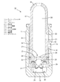
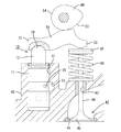
以下、本発明を具体化した実施形態1を図1乃至図5を参照して説明する。本実施形態の油圧式のラッシュアジャスタ10が適用される内燃機関の動弁装置について説明する。動弁装置は、ラッシュアジャスタ10、バルブ機構42、ロッカアーム50、及びカム49を備えて構成される。シリンダヘッド40の上面に凹み形成された取付孔41には、ラッシュアジャスタ10がプランジャ12を上向きに突出させた姿勢で取り付けられている。
<Embodiment 1>
A first embodiment embodying the present invention will be described below with reference to FIGS. A valve operating apparatus for an internal combustion engine to which the hydraulic lash adjuster 10 of the present embodiment is applied will be described. The valve gear includes the
バルブ機構42は、シリンダヘッド40のガイド孔43に上下移動可能に貫通されたバルブステム44と、バルブステム44の下端部に形成されたバルブ45とを備えて構成されている。バルブ45が上方へ移動すると、シリンダヘッド40内の吸排気口46が閉じてバルブ機構42が閉弁状態となり、バルブ45が下降すると、吸排気口46が開いてバルブ機構42が開弁状態となる。シリンダヘッド40の上面とバルブステム44の上端に固着した受け板47との間には、圧縮コイルバネからなるバルブスプリング48が設けられている。バルブスプリング48は、バルブ45を閉弁方向へ付勢しており、バルブ45が開弁方向に移動(下降)すると、バルブスプリング48の弾性復元力(付勢力)が増大していくようになっている。
The
ラッシュアジャスタ10とバルブ機構42の上方には、卵形をなすカム49が回転可能に設けられている。また、カム49とラッシュアジャスタ10及びバルブステム44との間には、ロッカアーム50が、その一端の支点部51をラッシュアジャスタ10のプランジャ12の上端の支承部19に載置させるとともに、他方の揺動端部52をバルブステム44の上端に載置した状態で設けられている。ロッカアーム50の上面には、支点部51と揺動端部52との間の位置においてカム49の外周面が摺接するようになっている。
Above the
カム49が回転すると、ロッカアーム50が、支点部51を中心として揺動端部52を上下に変位させるようにして揺動されるようになっている。カム49の円弧形をなすカムベース部53がロッカアーム50の上面に摺接する状態では、図4に示すように、ロッカアーム50がバルブスプリング48の付勢により上方位置にあってバルブ機構42が閉弁され、カムノーズ部54がロッカアーム50の上面に摺接する状態では、カム49がバルブスプリング48の付勢に抗してロッカアーム50を下方へ変位させるので、バルブ45が下降し、バルブ機構42が開弁される。
When the
バルブ機構42が開閉される間、プランジャ12の上端には、バルブスプリング48の付勢力が、バルブ45とロッカアーム50を介して下向きの押圧力として作用する。したがって、バルブ機構42の開度が大きくなるほど、プランジャ12に作用する下向きの押圧力が増大することになる。
While the
次に、ラッシュアジャスタ10について説明する。ラッシュアジャスタ10は、ボディ11とプランジャ12とを備えて構成される。
ボディ11は、円形の底面壁13の周縁から円筒状の周面壁14を立ち上げた有底筒状をなす。ボディ11の周面壁14における上端に近い位置には、その内外両周面間に貫通する外部連通孔15が形成され、外部連通孔15は、シリンダヘッド40内に設けた作動油供給路55に連通している。また、ボディ11の内周における外部連通孔15と対応する高さには、全周に亘って連続する同心状の拡径部16が形成されている。
Next, the
The
プランジャ12は、円形の底壁部17の周縁から円筒状の周壁部18を立ち上げた有底筒状をなしており、上からボディ11内に嵌め込まれ、ボディ11に対して上下移動するようになっている。プランジャ12の上端部はボディ11の上端から上方へ突出されており、このプランジャ12の上端部には、略半球状(ドーム状)の支承部19が形成されている。この支承部19の外面にはロッカアーム50の支点部51が上から当接され、この支承部19においてロッカアーム50の支点部51を支持するようになっている。
The
プランジャ12の周壁部18の外周には、全周に亘って連続する同心状の縮径部21が、その少なくとも一部をボディ11の拡径部16と対応させるように形成され、縮径部21と拡径部16との間には、全周に亘って連続する周方向の連通路22が形成されている。プランジャ12の周壁部18には、縮径部21の上端部位置において外周から内周まで貫通させた形態の内部連通孔23が形成されており、この内部連通孔23は、連通路22を介して外部連通孔15と連通している。
On the outer periphery of the
プランジャ12の中空内は低圧室24となっている。低圧室24には、シリンダヘッド40内の作動油供給路55から、外部連通孔15、連通路22及び内部連通孔23を順に通して作動油が供給されている。また、ボディ11の中空下端部には、プランジャ12の底壁部17によって低圧室24との間を仕切られた高圧室25が構成されており、高圧室25内には、後述する逆止弁27を通して低圧室24内の作動油が充填されているとともに、プランジャ12を上方へ付勢するための付勢バネ26が設けられている。
The hollow inside of the
ラッシュアジャスタ10の下端部には逆止弁27が設けられている。逆止弁27は、プランジャ12の底壁部17を上下に貫通する弁口28と、高圧室25内に収容されて弁口28を開閉する球形の弁体29と、リテーナ30内に収容されて弁体29を弁口28側へ付勢する弁バネ31とを備えて構成され、常には、付勢バネ26の付勢により弁体29が弁口28を閉じる閉弁状態に保持されている。プランジャ12が上昇すると、弁体29が弁口28から離間して逆止弁27が開弁し、低圧室24内の作動油が弁口28を通って高圧室25内に流入するようになっている。また、プランジャ12が下降するときには、弁体29が弁口28に押し付けられて逆止弁27が閉弁状態となり、高圧室25から低圧室24への作動油の流入が規制される。
A
ボディ11の内周面とプランジャ12の外周面との間の円筒状の空間(隙間)のうち、高圧室25から連通路22に至る領域は、プランジャ12の下降に伴って高圧室25内の作動油を連通路22へリークさせるためのリーク経路32(図2及び図3を参照)となっている。プランジャ12の外周面のうちリーク経路32と対応する領域には、周方向に延びる保持溝33が全周に亘って連続して形成されている。保持溝33の断面形状は方形であって、保持溝33の溝底面33aはプランジャ12の外周面と平行をなし、保持溝33の上面33bと下面33cは、プランジャ12の外周面と直角をなす。
Of the cylindrical space (gap) between the inner peripheral surface of the
かかる保持溝33には、耐油性を有する弾性材料(金属又は合成樹脂)からなるリング状部材34が取り付けられている。リング状部材34は、概ね円環形をなし、正確には、全周に亘って連続していない略C字形をなしている。リング状部材34の断面形状は、方形における1つの角部をテーパ状に切欠した五角形をなしている。リング状部材34の上面34aと下面34bは互いに平行をなし、内周面34cと外周面34dが互いに平行をなしている。外周面34dと下面34bとの間に位置するテーパ状の切欠面は、外周面34d及び下面34bに対して傾斜した受圧面35となっている。
A ring-shaped
かかるリング状部材34は、弾性的に縮径変形された状態で保持溝33内に収容され、常には、リング状部材34の弾性復元力により、リング状部材34の外周面34dがボディ11の内周面に対して弾性的に密着している。この状態では、リング状部材34の周方向における両端部の間の切欠空間は、リング状部材34の縮径変形を許容するとともに作動油の流通を許容するための連通部36となっている。また、リング状部材34の内周面34cと保持溝33の溝底面33aとの間には、リング状部材34の縮径変形(即ち、径方向の弾性変形)を許容するためのクリアランス37が確保されている。このクリアランス37は、リング状部材34がその両端同士を当接させて連通部36がなくなった状態、即ちリング状部材34の縮径方向の変形量が最大になった状態においても、確保されるようになっている。
The ring-shaped
また、リング状部材34の受圧面35及び下面34bには、リーク経路32のうちリング状部材34よりも下方(高圧室25側)に充填されている作動油が接触しているため、高圧室25内に作動油の圧力によりリング状部材34は上方へ押圧されている。これにより、リング状部材34の上面34aにおける内周側の領域は、保持溝33の上面33bに対して面接触状態で当接している。一方、リング状部材34の下面34bは保持溝33の下面33cに対して隙間を空けている。また、リング状部材34が径方向に変形する際には、リング状部材34の上面34aが保持溝33の上面33bに摺接するようになっている。
Further, the
次に、本実施形態の作用を説明する。 Next, the operation of this embodiment will be described.
動弁装置が正常に作動している状態では、バルブステム44とロッカアーム50との間やロッカアーム50とカム49との間に隙間が発生すると、付勢バネ26の付勢力によりプランジャ12が上昇して隙間を埋める。このとき、高圧室25内の圧力が低下するので、逆止弁27が開弁して低圧室24内の作動油が高圧室25内に流入し、高圧室25内の作動油がリーク経路32を通ってリークすることはない。
In a state where the valve operating device is operating normally, if a gap is generated between the valve stem 44 and the
また、正常な作動状態において、カム49からロッカアーム50への押圧力が増大してロッカアーム50からプランジャ12に対する荷重が増大した場合には、プランジャ12が下降する。このとき、高圧室25内の圧力が上昇するので、逆止弁27は閉弁状態に保持され、高圧室25内の作動油がリーク経路32を通ってリークする。このときのプランジャ12に作用する荷重は正常値の範囲内であるから、リング状部材34は、殆ど弾性変形せずに、リーク経路32内に進出した状態、即ち、リング状部材34の外周面をボディ11の内周面にほぼ密着させた状態を保つ。したがって、作動油は、連通部36を通ってリークすることになる。この連通部36を通るときの流動抵抗により、プランジャ12の下降に抗する減衰力が発生し、プランジャ12に作用する荷重が減衰されるので、プランジャ12は比較的低速で下降する。
Further, in a normal operating state, when the pressing force from the
さて、上記の正常動作とは異なり、動弁装置において異常運動が発生すると、それが原因となってプランジャ12が正常な昇降域を超えて過剰に上昇することがある。この場合、ロッカアーム50の支点部51の位置が高くなるため、ロッカアーム50にカム49のカムベース部54が摺接してロッカアーム50の揺動端部52が最も上方の位置に達した状態になっても、バルブ機構42が完全に閉弁しないという状態が続く虞がある。
Now, unlike the above-mentioned normal operation, when an abnormal motion occurs in the valve operating device, the
ここで、プランジャ12が正常な昇降域を超えて過剰に上昇した状態で、バルブ機構42が最も大きく開弁したとき(バルブ45が最も下方に位置したとき)にバルブスプリング48に蓄勢される付勢力(弾性復元力)は、正常域を超えて大きくなり、これにより、ロッカアーム50からプランジャ12に作用する下向きの押圧力も、正常域を超えて過剰に大きくなる。すると、高圧室25内の作動油の圧力も正常域を超えた大きな値となり、この大きな圧力により、リング状部材34が弾性的に縮径変形することになる。このリング状部材34の径方向への弾性変形により、リング状部材34の外周面とボディ11の内周面との間隔が広がり、リング状部材34によって大部分が塞がれていたリーク経路32が開放されて、リーク経路32における作動油の流動可能範囲が拡大するので、この拡大したリーク経路32を通ることにより、高圧室25内の作動油が正常時よりも大きな流量でリークする。つまり、高圧室25内からリークする作動油の流動抵抗が低下する。この流動抵抗は、プランジャ12が下降するときの抵抗となるものであるから、プランジャ12は正常時よりも速い速度で下降し、プランジャ12の高さが正常時の昇降領域の範囲内に戻ることになる。
Here, when the
また、リング状部材34には、リング状部材34の変形方向である径方向に対して傾斜した形態であって高圧室25側からの作動油の圧力を受けることが可能な受圧面35が形成されているので、作動油から受圧面35に作用する圧力によってリング状部材34には径方向の押圧力が付与されることになる。したがって、リング状部材34は確実に径方向に変形することができる。
Further, the ring-shaped
また、リング状部材34は、プランジャ12の外周面に形成した保持溝33内に収容されており、図3に示すように、リング状部材34の径方向の変形量が最大となった状態において、保持溝33の溝底面33aとリング状部材34の内周面34cとの間に径方向のクリアランス37が確保されるようになっている。したがって、プランジャ12がボディ11に対して径方向に偏心するように位置ずれした場合には、保持溝33の溝底面33aとリング状部材34の内周面34cとの間に確保されている径方向のクリアランス37によって位置ずれが吸収される。
Further, the ring-shaped
また、リング状部材34には、作動油の流動を許容する連通部36が形成されているので、連通部36の開口面積を適宜設定することにより、プランジャ12に対して作用する下降方向の力が正常の範囲内である場合における作動油のリーク時の流動抵抗を任意に設定することができる。
Further, since the ring-shaped
<実施形態2>
次に、本発明を具体化した実施形態2を図6を参照して説明する。本実施形態2は、リング状部材60を上記実施形態1とは異なる構成としたものである。その他の構成については上記実施形態1と同じであるため、同じ構成については、同一符号を付し、構造、作用及び効果の説明は省略する。
<Embodiment 2>
Next, a second embodiment of the present invention will be described with reference to FIG. In the second embodiment, the ring-shaped
本実施形態2のリング状部材60は、全周に亘って連続する円環形をなすとともに、外周の一部を凹み状に(内周側へ貫通しない形態で)切欠することによって連通部61を形成したものである。また、リング状部材60は、合成樹脂製であり、高圧室32側からの圧力が正常域を超えて増大したときには、真円を歪な形に変形させるように径方向へ弾性的に縮径変形するようになっている。
The ring-shaped
<他の実施形態>
本発明は上記記述及び図面によって説明した実施形態に限定されるものではなく、例えば次のような実施態様も本発明の技術的範囲に含まれる。
(1)上記実施形態ではリング状部材がリーク経路から退避するときに縮径するように変形させたが、本発明によれば、リング状部材がリーク経路から退避するときに拡径するように変形させてもよい。この場合、リング状部材を保持する保持溝は、ボディの内周面に形成すればよい。
(2)上記実施形態では受圧面をリング状部材の全周(全長)に亘って形成したが、本発明によれば、受圧面を、リング状部材の長さ方向における一部のみに形成してもよい。
(3)上記実施形態ではリング状部材の径方向の変形量が最大となった状態において、保持溝の溝底面とリング状部材の周面との間に径方向のクリアランスを確保したが、本発明によれば、リング状部材の径方向の変形量が最大となった状態において、保持溝の溝底面とリング状部材の周面との間に径方向のクリアランスが空かない構成としてもよい。
(4)上記実施形態ではリング状部材に連通部を1つだけ形成したが、本発明によれば、1つのリング状部材に複数の連通部を形成してもよい。
(5)上記実施形態ではリング状部材に連通部を形成したが、本発明によれば、リング状部材に連通部を形成しない形態としてもよい。
<Other embodiments>
The present invention is not limited to the embodiments described with reference to the above description and drawings. For example, the following embodiments are also included in the technical scope of the present invention.
(1) In the above embodiment, the ring-shaped member is deformed so as to reduce in diameter when retracted from the leak path. However, according to the present invention, the ring-shaped member is expanded in diameter when retracted from the leak path. It may be deformed. In this case, the holding groove for holding the ring-shaped member may be formed on the inner peripheral surface of the body.
(2) In the above embodiment, the pressure receiving surface is formed over the entire circumference (full length) of the ring-shaped member. However, according to the present invention, the pressure receiving surface is formed only in a part in the length direction of the ring-shaped member. May be.
(3) In the above embodiment, the radial clearance is secured between the bottom surface of the holding groove and the peripheral surface of the ring member in a state where the radial deformation amount of the ring member is maximized. According to the invention, in a state where the radial deformation amount of the ring-shaped member is maximized, the radial clearance may not be provided between the groove bottom surface of the holding groove and the peripheral surface of the ring-shaped member.
(4) In the above embodiment, only one communication portion is formed on the ring-shaped member. However, according to the present invention, a plurality of communication portions may be formed on one ring-shaped member.
(5) In the above embodiment, the communication portion is formed on the ring-shaped member. However, according to the present invention, the communication portion may not be formed on the ring-shaped member.
10…ラッシュアジャスタ
11…ボディ
12…プランジャ
25…高圧室
32…リーク経路
33…保持溝
34…リング状部材
35…受圧面
36…連通部
37…クリアランス
DESCRIPTION OF
Claims (4)
前記ボディ内に昇降可能に設けられた有底筒状のプランジャとを備え、
前記ボディの下端部には前記プランジャの底壁部で区画された高圧室が形成され、
前記プランジャが下降するときには、前記高圧室内の作動油が前記ボディの内周面と前記プランジャの外周面との間のリーク経路を通ってリークするようになっているラッシュアジャスタにおいて、
前記ボディの内周面と前記プランジャの外周面との間には、常には前記リーク流路内に進出する状態を保ち、前記高圧室側からの作動油の圧力の増大により前記リーク流路から退避するように径方向に弾性変形して前記リーク経路内における作動油の流動抵抗を低減させるリング状部材が設けられていることを特徴とするラッシュアジャスタ。 A bottomed cylindrical body,
A bottomed cylindrical plunger provided so as to be movable up and down in the body,
A high-pressure chamber defined by a bottom wall of the plunger is formed at the lower end of the body,
When the plunger is lowered, the hydraulic oil in the high pressure chamber leaks through a leak path between the inner peripheral surface of the body and the outer peripheral surface of the plunger.
Between the inner peripheral surface of the body and the outer peripheral surface of the plunger, the state of always advancing into the leak flow path is maintained, and the pressure of the hydraulic oil from the high pressure chamber side increases so that the leak flow path A lash adjuster characterized in that a ring-shaped member is provided which is elastically deformed in a radial direction so as to retract and reduces a flow resistance of hydraulic oil in the leak path.
前記リング状部材の径方向の変形量が最大となった状態において、前記保持溝の溝底面と前記リング状部材の周面との間に径方向のクリアランスが確保されるようになっていることを特徴とする請求項1又は請求項2記載のラッシュアジャスタ。 The ring-shaped member is accommodated in a holding groove formed on one peripheral surface of the inner peripheral surface of the body or the outer peripheral surface of the plunger,
A radial clearance is secured between the bottom surface of the holding groove and the peripheral surface of the ring-shaped member in a state where the amount of radial deformation of the ring-shaped member is maximized. The lash adjuster according to claim 1 or 2, characterized in that.
Priority Applications (6)
| Application Number | Priority Date | Filing Date | Title |
|---|---|---|---|
| JP2008019066A JP4865740B2 (en) | 2008-01-30 | 2008-01-30 | Rush adjuster |
| DE602009000863T DE602009000863D1 (en) | 2008-01-30 | 2009-01-15 | Lash adjuster |
| AT09000524T ATE502186T1 (en) | 2008-01-30 | 2009-01-15 | GAME EQUATION ELEMENT |
| EP09000524A EP2085580B1 (en) | 2008-01-30 | 2009-01-15 | Lash adjuster |
| US12/357,477 US8001941B2 (en) | 2008-01-30 | 2009-01-22 | Lash adjuster |
| HK10100397.7A HK1133449B (en) | 2008-01-30 | 2010-01-14 | Lash adjuster |
Applications Claiming Priority (1)
| Application Number | Priority Date | Filing Date | Title |
|---|---|---|---|
| JP2008019066A JP4865740B2 (en) | 2008-01-30 | 2008-01-30 | Rush adjuster |
Publications (2)
| Publication Number | Publication Date |
|---|---|
| JP2009180123A JP2009180123A (en) | 2009-08-13 |
| JP4865740B2 true JP4865740B2 (en) | 2012-02-01 |
Family
ID=40433750
Family Applications (1)
| Application Number | Title | Priority Date | Filing Date |
|---|---|---|---|
| JP2008019066A Expired - Fee Related JP4865740B2 (en) | 2008-01-30 | 2008-01-30 | Rush adjuster |
Country Status (5)
| Country | Link |
|---|---|
| US (1) | US8001941B2 (en) |
| EP (1) | EP2085580B1 (en) |
| JP (1) | JP4865740B2 (en) |
| AT (1) | ATE502186T1 (en) |
| DE (1) | DE602009000863D1 (en) |
Families Citing this family (6)
| Publication number | Priority date | Publication date | Assignee | Title |
|---|---|---|---|---|
| JP2014156782A (en) * | 2013-02-14 | 2014-08-28 | Otics Corp | Lash adjuster |
| US9051854B1 (en) * | 2014-03-04 | 2015-06-09 | Caterpillar Inc. | Valve train hydraulic lash adjuster with partial recirculation feature |
| JP7099260B2 (en) * | 2018-11-06 | 2022-07-12 | トヨタ自動車株式会社 | Internal combustion engine valve operating system |
| GB2578338B (en) * | 2019-03-07 | 2020-12-09 | Cox Powertrain Ltd | Marine outboard motor with valve train having adjustable lash |
| JP2021124053A (en) * | 2020-02-05 | 2021-08-30 | 株式会社オティックス | Rush adjuster |
| CN111720184B (en) * | 2020-06-29 | 2024-07-02 | 杭州新坐标科技股份有限公司 | Plane hydraulic support piece for large-sized engine |
Family Cites Families (28)
| Publication number | Priority date | Publication date | Assignee | Title |
|---|---|---|---|---|
| US2688317A (en) * | 1949-12-02 | 1954-09-07 | Voorhies Carl | Hydraulic clearance regulator |
| US2870757A (en) | 1956-07-30 | 1959-01-27 | Ernest L Dayton | Hydraulic valve tappet |
| FR1163535A (en) | 1956-12-19 | 1958-09-29 | Anciens Etablissements Panhard | Hydraulic device for adjusting the valve clearance of an internal combustion engine |
| US2943611A (en) * | 1958-01-22 | 1960-07-05 | Johnson Products Inc | Hydraulic tappets |
| US2942595A (en) | 1958-04-09 | 1960-06-28 | Johnson Products Inc | Hydraulic tappet |
| US2956557A (en) * | 1958-12-11 | 1960-10-18 | Morris V Dadd | Hydraulic tappets |
| DE1273256B (en) * | 1965-02-13 | 1968-07-18 | Motomak | Self-adjusting, hydraulically adjusting lash adjuster for the valve control of internal combustion engines |
| JPS5884306A (en) * | 1981-11-13 | 1983-05-20 | Omron Tateisi Electronics Co | Programming device of programmable controller |
| JPS59137310A (en) * | 1983-01-19 | 1984-08-07 | Shin Etsu Chem Co Ltd | Manufacture of silicon nitride powder |
| JPS6137408A (en) * | 1984-07-31 | 1986-02-22 | Hitachi Metals Ltd | Plunger for transfer molding machine |
| JPS62225707A (en) * | 1986-03-27 | 1987-10-03 | Honda Motor Co Ltd | Sealed hydraulic lash adjuster |
| DE3800945C1 (en) | 1988-01-15 | 1989-02-16 | Daimler-Benz Ag, 7000 Stuttgart, De | |
| US5129373A (en) | 1991-12-16 | 1992-07-14 | General Motors Corporation | Self-contained hydraulic lash adjuster with pressurizing diaphragm |
| DE4427943A1 (en) * | 1994-08-06 | 1996-02-08 | Schaeffler Waelzlager Kg | Hydraulic lash adjuster for valve control of internal combustion engines |
| DE19529044A1 (en) | 1995-08-08 | 1997-02-13 | Schaeffler Waelzlager Kg | Hydraulic lash adjuster for a valve control of an internal combustion engine |
| US5622147A (en) * | 1996-03-08 | 1997-04-22 | Eaton Corporation | Hydraulic lash adjuster |
| US5855191A (en) | 1997-06-23 | 1999-01-05 | Eaton Corporation | Metering valve for ball plunger or pushrod socket |
| US5901676A (en) | 1997-08-28 | 1999-05-11 | Eaton Corporation | Hydraulic lash compensator |
| US5862785A (en) | 1998-01-26 | 1999-01-26 | Eaton Corporation | Hydraulic lash adjuster and improved oil flow path therefor |
| US6006710A (en) | 1998-08-31 | 1999-12-28 | Ford Global Technologies, Inc. | Hydraulic lash adjuster mechanism with pressure controlled leak down |
| US6039017A (en) | 1999-02-18 | 2000-03-21 | General Motors Corporation | Hydraulic lash adjuster with lash |
| DE19949497A1 (en) * | 1999-10-14 | 2001-04-19 | Volkswagen Ag | Hydraulic damping element used in valve drives of internal combustion engines comprises a spring-loaded piston which can move in a cylinder and a leakage gap arranged between the inner wall of the cylinder and the outer casing of the piston |
| EP1267046B1 (en) | 2001-06-15 | 2004-09-15 | EATON AUTOMOTIVE S.p.A. | Hydraulic lash adjuster |
| EP1267045A1 (en) | 2001-06-15 | 2002-12-18 | EATON AUTOMOTIVE S.p.A. | Hydraulic lash adjuster for a valve train in an internal combustion engine |
| JP2003336507A (en) * | 2002-05-20 | 2003-11-28 | Toyota Industries Corp | Rush adjustor for valve mechanism |
| JP4005934B2 (en) | 2003-03-14 | 2007-11-14 | 株式会社オティックス | Hydraulic lash adjuster for internal combustion engines |
| DE602004021179D1 (en) | 2004-06-29 | 2009-07-02 | Eaton Srl | Open mini-valve clearance compensation element |
| JP2009013830A (en) * | 2007-07-03 | 2009-01-22 | Otics Corp | Rush adjuster |
-
2008
- 2008-01-30 JP JP2008019066A patent/JP4865740B2/en not_active Expired - Fee Related
-
2009
- 2009-01-15 DE DE602009000863T patent/DE602009000863D1/en active Active
- 2009-01-15 EP EP09000524A patent/EP2085580B1/en not_active Not-in-force
- 2009-01-15 AT AT09000524T patent/ATE502186T1/en not_active IP Right Cessation
- 2009-01-22 US US12/357,477 patent/US8001941B2/en not_active Expired - Fee Related
Also Published As
| Publication number | Publication date |
|---|---|
| JP2009180123A (en) | 2009-08-13 |
| ATE502186T1 (en) | 2011-04-15 |
| EP2085580A1 (en) | 2009-08-05 |
| HK1133449A1 (en) | 2010-03-26 |
| US20090188457A1 (en) | 2009-07-30 |
| DE602009000863D1 (en) | 2011-04-28 |
| US8001941B2 (en) | 2011-08-23 |
| EP2085580B1 (en) | 2011-03-16 |
Similar Documents
| Publication | Publication Date | Title |
|---|---|---|
| JP4865740B2 (en) | Rush adjuster | |
| CN102449272B (en) | Hydraulic lash adjuster for internal combustion engine | |
| WO2009101907A1 (en) | Lash adjuster | |
| JP4178158B2 (en) | Rush adjuster with internal combustion engine deactivation mechanism | |
| JP5791185B2 (en) | Fluid pressure cylinder | |
| JP5973243B2 (en) | Rocker arm with built-in lash adjuster | |
| JP5044314B2 (en) | Rush adjuster oil supply structure | |
| JP5456567B2 (en) | Rush adjuster | |
| JP6682022B2 (en) | Tappet | |
| CN106812562A (en) | Lash adjuster | |
| EP1903190B1 (en) | Lash adjuster | |
| JP6106578B2 (en) | Rush adjuster | |
| JP6009169B2 (en) | Rush adjuster | |
| JP2024100684A (en) | Lash adjuster | |
| JP4731521B2 (en) | Rash adjuster and retainer assembly method | |
| JP2024081836A (en) | Lash adjuster | |
| JP6290749B2 (en) | Rush adjuster | |
| JP4715611B2 (en) | Rush adjuster and internal combustion engine | |
| JP2017082643A (en) | Rush adjuster | |
| JP6246066B2 (en) | Rush adjuster | |
| JP2018178871A (en) | Lash adjuster | |
| JP2021124053A (en) | Rush adjuster | |
| HK1133449B (en) | Lash adjuster | |
| JP2010265874A (en) | Rush adjuster | |
| JP2017072108A (en) | Lash adjuster assembly structure |
Legal Events
| Date | Code | Title | Description |
|---|---|---|---|
| A621 | Written request for application examination |
Free format text: JAPANESE INTERMEDIATE CODE: A621 Effective date: 20100709 |
|
| A977 | Report on retrieval |
Free format text: JAPANESE INTERMEDIATE CODE: A971007 Effective date: 20110811 |
|
| A131 | Notification of reasons for refusal |
Free format text: JAPANESE INTERMEDIATE CODE: A131 Effective date: 20110823 |
|
| TRDD | Decision of grant or rejection written | ||
| A01 | Written decision to grant a patent or to grant a registration (utility model) |
Free format text: JAPANESE INTERMEDIATE CODE: A01 Effective date: 20111108 |
|
| A01 | Written decision to grant a patent or to grant a registration (utility model) |
Free format text: JAPANESE INTERMEDIATE CODE: A01 |
|
| A61 | First payment of annual fees (during grant procedure) |
Free format text: JAPANESE INTERMEDIATE CODE: A61 Effective date: 20111110 |
|
| FPAY | Renewal fee payment (event date is renewal date of database) |
Free format text: PAYMENT UNTIL: 20141118 Year of fee payment: 3 |
|
| R150 | Certificate of patent or registration of utility model |
Ref document number: 4865740 Country of ref document: JP Free format text: JAPANESE INTERMEDIATE CODE: R150 Free format text: JAPANESE INTERMEDIATE CODE: R150 |
|
| R250 | Receipt of annual fees |
Free format text: JAPANESE INTERMEDIATE CODE: R250 |
|
| R250 | Receipt of annual fees |
Free format text: JAPANESE INTERMEDIATE CODE: R250 |
|
| R250 | Receipt of annual fees |
Free format text: JAPANESE INTERMEDIATE CODE: R250 |
|
| R250 | Receipt of annual fees |
Free format text: JAPANESE INTERMEDIATE CODE: R250 |
|
| R250 | Receipt of annual fees |
Free format text: JAPANESE INTERMEDIATE CODE: R250 |
|
| R250 | Receipt of annual fees |
Free format text: JAPANESE INTERMEDIATE CODE: R250 |
|
| LAPS | Cancellation because of no payment of annual fees |