JP4875559B2 - Body frame structure - Google Patents
Body frame structure Download PDFInfo
- Publication number
- JP4875559B2 JP4875559B2 JP2007183546A JP2007183546A JP4875559B2 JP 4875559 B2 JP4875559 B2 JP 4875559B2 JP 2007183546 A JP2007183546 A JP 2007183546A JP 2007183546 A JP2007183546 A JP 2007183546A JP 4875559 B2 JP4875559 B2 JP 4875559B2
- Authority
- JP
- Japan
- Prior art keywords
- frame
- width direction
- vehicle width
- cross member
- vehicle
- Prior art date
- Legal status (The legal status is an assumption and is not a legal conclusion. Google has not performed a legal analysis and makes no representation as to the accuracy of the status listed.)
- Expired - Fee Related
Links
Images


Landscapes
- Body Structure For Vehicles (AREA)
Description
本発明は、エンジンルームの左右両側に車体前後方向に配置されるフロントサイドフレームと、車室の左右両側に車体前後方向に配置されるサイドシルと、車室の車幅方向中央部に車体前後方向に配置されるセンターフレームと、前記フロントサイドフレームの後端、前記サイドシルの前端および前記センターフレームの前端を連結する連結部材とを備えた車体フレーム構造に関する。 The present invention includes a front side frame disposed in the longitudinal direction of the vehicle body on the left and right sides of the engine compartment, a side sill disposed in the longitudinal direction of the vehicle body on the left and right sides of the vehicle compartment, and the vehicle body longitudinal direction in the vehicle width direction central portion of the vehicle compartment. And a connecting member that connects the rear end of the front side frame, the front end of the side sill, and the front end of the center frame.
エンジンルームに配置したフロントサイドフレームの後端および車室の側部に配置したサイドシルの前端を、車幅方向に延びるアウトリガーで接続したフレーム構造(従来例)と、エンジンルームに配置したフロントサイドフレームの後端および車室の中央部に配置したフロアフレームの前端を、車幅方向に延びるアウトリガーで接続したフレーム構造(第1、第2実施例)とが、下記特許文献1により公知である。
ところで上記従来のものは、アウトリガーが車幅方向に配置されているので、フロントサイドフレームに入力された荷重でアウトリガーが容易に変形してしまい、フロントサイドフレームに入力された前記前記荷重を効率的にサイドシルあるいはフロアフレームに伝達して吸収することができない可能性があった。 By the way, since the outrigger is arranged in the vehicle width direction in the above-mentioned conventional one, the outrigger easily deforms due to the load input to the front side frame, and the load input to the front side frame is efficiently processed. In some cases, it could not be transmitted to the side sill or floor frame and absorbed.
本発明は前述の事情に鑑みてなされたもので、フロントサイドフレームに入力された衝突荷重をサイドシルおよびセンターフレームに効率的に伝達して吸収することを目的とする。 The present invention has been made in view of the above-described circumstances, and an object thereof is to efficiently transmit and absorb a collision load input to a front side frame to a side sill and a center frame.
上記目的を達成するために、請求項1に記載された発明によれば、車室を囲むフレームが、車体前後方向に配置される左右一対のサイドシルと、車幅方向に配置されるダッシュボードロアクロスメンバと、車幅方向に配置されるミドルクロスメンバと、前記サイドシルの前端および前記ダッシュボードロアクロスメンバの左右両端を斜めに接続する一対のアウトリガーと、前記サイドシルの後端および前記ミドルクロスメンバの左右両端を斜めに接続する一対のガセットとで八角形に構成され、エンジンルームの左右両側に車体前後方向に配置されるフロントサイドフレームと、車室の車幅方向中央部に車体前後方向に配置されるセンターフレームと、前記フロントサイドフレームの後端、前記サイドシルの前端および前記センターフレームの前端を連結する連結部材とを備えた車体フレーム構造であって、前記連結部材は、前記フロントサイドフレームの後端から車両幅方向外側に向かって斜め後方に延びて前記サイドシルの前端に連なるアウトリガーと、前記フロントサイドフレームの後端から車両幅方向内側に向かって斜め後方に延びて前記センターフレームの前端に連なるセンターフレームエクステンションと、左右一対の縦フレームを前後一対の横フレームで四角枠状に接続して構成されたフロントサブフレームの後端を前記センターフレームエクステンションの前端に取り付けるフロントサブフレーム取付部とを備えることを特徴とする車体フレーム構造が提案される。 In order to achieve the above object, according to the first aspect of the present invention, the frame surrounding the passenger compartment has a pair of left and right side sills arranged in the vehicle body longitudinal direction and a dashboard lower arranged in the vehicle width direction. A cross member, a middle cross member arranged in the vehicle width direction, a pair of outriggers that obliquely connect the front end of the side sill and the left and right ends of the dashboard lower cross member, and the rear end of the side sill and the middle cross member A pair of gussets that diagonally connect the left and right ends of the engine , and an octagonal configuration, a front side frame that is arranged in the longitudinal direction of the vehicle body on the left and right sides of the engine room, and a longitudinal direction in the vehicle width direction center of the vehicle compartment Center frame arranged, rear end of front side frame, front end of side sill, and center frame A vehicle body frame structure that includes a connecting member connecting the front end, the connecting member includes a outriggers connected to the front end of the side sill from the rear end extends obliquely rearward toward the outer side in the vehicle width direction of the front side frame A center frame extension extending diagonally rearward from the rear end of the front side frame toward the inside in the vehicle width direction and continuing to the front end of the center frame, and a pair of left and right vertical frames connected to each other in a square frame shape by a pair of front and rear horizontal frames There is proposed a vehicle body frame structure comprising a front subframe attachment portion for attaching a rear end of a front subframe configured as described above to a front end of the center frame extension .
また請求項2に記載された発明によれば、請求項1の構成に加えて、前記連結部材の前記アウトリガー、前記センターフレームエクステンションおよび前記フロントサブフレーム取付部を連続する一部材で形成したことを特徴とする車体フレーム構造が提案される。
According to the invention described in
請求項1の構成によれば、車室を囲むフレームを、左右一対のサイドシルと、ダッシュボードロアクロスメンバと、ミドルクロスメンバと、サイドシルの前端およびダッシュボードロアクロスメンバの左右両端を斜めに接続する一対のアウトリガーと、サイドシルの後端およびミドルクロスメンバの左右両端を斜めに接続する一対のガセットとで八角形に構成したので、四角形のフレームに比べて剛性が増加して車室の変形が効果的に抑制される。何故ならば、外力に対して最も変形し難い形状は円形であり、八角形は四角形よりも円形に近いからである。この八角形のフレーム構造は、正面衝突時だでけでなく、サイドシル側から荷重が入力する側面衝突時にも車室の変形を最小限に抑えることができる。
According to the configuration of
またエンジンルームに車体前後方向に配置されるフロントサイドフレームの後端と、サイドシルの前端と、車室の中央部に車体前後方向に配置されるセンターフレームの前端とを連結する連結部材が、フロントサイドフレームの後端から車両幅方向外側に向かって斜め後方に延びてサイドシルの前端に連なるアウトリガーと、フロントサイドフレームの後端から車両幅方向内側に向かって斜め後方に延びてセンターフレームの前端に連なるセンターフレームエクステンションとを備えているので、車両の衝突時にフロントサイドフレームに入力された後向きの衝突荷重を、連結部材のアウトリガーおよびセンターフレームエクステンションを介してサイドシルおよびセンターフレームエクステンションに分散し、衝突荷重による車室の変形を最小限に抑えることができる。このとき、連結部材のアウトリガーおよびセンターフレームエクステンションは車幅方向に対して傾斜しているので、それ自身が変形することなく衝突荷重を効率的にサイドシルおよびセンターフレームエクステンションに伝達することができる。 Further the rear end of the front side frame which is arranged in the longitudinal direction of the vehicle body into the engine room, and the front end of the sub idosyl, a connecting member for connecting the front end of the center frame arranged in the longitudinal direction of the vehicle body in a central portion of the vehicle compartment, Outriggers that extend diagonally rearward from the rear end of the front side frame toward the vehicle width direction outer side and continue to the front end of the side sill; and front ends of the center frame that extend diagonally rearward from the rear end of the front side frame toward the vehicle width direction inner side The rear-side collision load input to the front side frame at the time of a vehicle collision is distributed to the side sill and center frame extension via the outriggers and center frame extension of the connecting member. Deformation of passenger compartment due to load It can be suppressed to a small limited. At this time, since the outrigger and the center frame extension of the connecting member are inclined with respect to the vehicle width direction, the collision load can be efficiently transmitted to the side sill and the center frame extension without being deformed.
しかも連結部材のセンターフレームエクステンションの前端に、左右一対の縦フレームを前後一対の横フレームで四角枠状に接続して構成されたフロントサブフレームの後端を取り付けるフロントサブフレーム取付部を設けたので、車両の前面衝突時に前方からフロントサブフレームに荷重が入力したとき、サイドシルおよびセンターフレームに接続された連結部材からフロントサブフレームに反力を作用させ、そのフロントサブフレームを確実に圧壊させて衝突荷重を吸収することができる。In addition, a front subframe mounting portion is provided at the front end of the center frame extension of the connecting member to attach the rear end of the front subframe formed by connecting a pair of left and right vertical frames in a square frame shape with a pair of front and rear horizontal frames. When a load is input to the front subframe from the front during a frontal collision of the vehicle, a reaction force is applied to the front subframe from the connecting member connected to the side sill and the center frame, and the front subframe is reliably crushed and collided. The load can be absorbed.
また請求項2の構成によれば、連結部材のアウトリガー、センターフレームエクステンションおよびフロントサブフレーム取付部を連続する一部材で形成したので、それらを別部材で構成して結合する場合に比べて、強度が向上して荷重の確実な伝達が可能になるだけでなく、部品点数を削減してコストを削減することができる。 According to the second aspect of the present invention, since the outrigger of the connecting member, the center frame extension, and the front sub-frame mounting portion are formed as one continuous member, the strength is higher than that in the case where they are configured as separate members and combined. As a result, the load can be reliably transmitted and the number of parts can be reduced to reduce the cost.
以下、本発明の実施の形態を添付図面に基づいて説明する。 Hereinafter, embodiments of the present invention will be described with reference to the accompanying drawings.
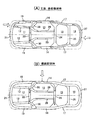
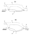
図1〜図7は本発明の実施の形態を示すもので、図1は自動車の車体フレームを下面から見た図、図2は図1の2方向矢視図、図3は図1の3部拡大図、図4は図3の4−4線断面図、図5は図1に保護エリアおよびエネルギー吸収エリアの形状を書き加えた図、図6は正面・後面衝突時および側面衝突時の荷重伝達経路を示す図、図7は正面衝突時のフロントサブフレームの変形を説明する図である。 1 to 7 show an embodiment of the present invention. FIG. 1 is a view of a body frame of an automobile as viewed from below, FIG. 2 is a view taken in the direction of the arrow in FIG. 1, and FIG. 4 is a cross-sectional view taken along line 4-4 of FIG. 3, FIG. 5 is a diagram in which the shapes of the protection area and the energy absorption area are added to FIG. 1, and FIG. 6 is a front / rear collision and a side collision. FIG. 7 is a diagram illustrating a load transmission path, and FIG. 7 is a diagram illustrating deformation of the front subframe at the time of a frontal collision.
図1および図2に示すように、自動車の車体フレームは、エンジンルーム11の左右両側部に沿って車体前後方向に延びる左右一対のフロントサイドフレーム12,12と、車室13の左右両側部に沿って車体前後方向に延びる左右一対のサイドシル14,14と、燃料タンク収納部15およびトランクルーム16の左右両側部に沿って車体前後方向に延びる左右一対のリヤサイドフレーム17,17と、フロントサイドフレーム12,12の前端から後上方に延び、左右のサイドシル14,14の前端から立ち上がる左右一対のフロントピラーロア18,18の上端に連結される左右一対のアッパーメンバ19,19と、車幅方向に延びてフロントサイドフレーム12,12の前端にフロントサイドフレームエクステンション20…を介して両端が接続されたフロントバンパービーム21と、車幅方向に延びて左右のフロントサイドフレーム12,12の後端間を接続するダッシュボードロアクロスメンバ22と、車幅方向に延びて左右のサイドシル14,14の前後方向中間部間を接続するフロントクロスメンバ23と、車幅方向に延びて左右のリヤサイドフレーム17,17の前端間を接続するミドルクロスメンバ24と、車幅方向に延びて左右のリヤサイドフレーム17,17の前後方向中間部間を接続するリヤクロスメンバ25と、車幅方向に延びて左右のリヤサイドフレーム17,17の後端間を接続するリヤバンパービーム26と、幅方向に延びてリヤクロスメンバ25およびリヤバンパービーム26間で左右のリヤサイドフレーム17,17を接続するリヤエンドフレーム27と、ダッシュボードロアクロスメンバ22からミドルクロスメンバ24へと延びるフロアトンネル28の左右両側に沿って延びる左右一対のセンターフレーム29,29と、フロントサイドフレーム12,12、サイドシル14,14およびセンターフレーム29,29を連結する左右一対の連結部材30,30と、左右のフロントサイドフレーム12,12の下部に支持されるフロントサブフレーム31とを備える。
As shown in FIG. 1 and FIG. 2, the body frame of an automobile is provided on a pair of left and right
フロントサブフレーム31は、左右一対の縦フレーム32,32を前後一対の横フレーム33,34で四角枠状に接続して構成され、縦フレーム32,32の前端がゴムブッシュジョイント35,35を介してフロントサイドフレーム12,12の前端下面に弾性支持されるとともに、縦フレーム32,32の後端がゴムブッシュジョイント36,36を介して連結部材30,30の下面に弾性支持される。
The
次に、図1〜図4を参照して連結部材30,30の構造を説明する。左右の連結部材30,30は鏡面対称な形状を有するため、その一方について説明する。
Next, the structure of the connecting
図1に網掛けして示す連結部材30は、金属パネルをプレス成形した単一の部材で構成されるもので、前端に下向きにカップ状に突出するフロントサブフレーム取付部30aを備え、フロントサブフレーム取付部30aから車幅方向外側かつ後方に向かってアウトリガー30bが斜めに延びるとともに、フロントサブフレーム取付部30aから車幅方向内側かつ後方に向かってセンターフレームエクステンション30cが斜めに延びている。
The connecting
連結部材30のフロントサブフレーム取付部30aに隣接するセンターフレームエクステンション30cの車幅方向内面にダッシュボードロアクロスメンバ22の左右両端部が接続されるとともに、そこから斜め後方に延びるセンターフレームエクステンション30cの後端がセンターフレーム29の前端に接続される。また連結部材30のアウトリガー30bの前端がフロントサイドフレーム12の後端に接続され、後端がサイドシル14の前端に接続される。
The left and right ends of the dashboard
連結部材30のフロントサブフレーム取付部30aの内部には前記ゴムブッシュジョイント36が収納され、それを貫通するボルト37にフロントサブフレーム31の後部が支持される(図4参照)。尚、フロントサブフレーム31の前部も、同様の構造のゴムブッシュジョイント35(図1参照)を介してフロントサイドフレーム12の下面に支持される。
The
図1および図5を併せて参照すると明らかなように、第1の保護領域である車室13を囲むフレームは、平面視で八角形状に構成される。即ち、車体前後方向に延びる左右のサイドシル14,14と、車幅方向に延びるダッシュボードロアクロスメンバ22およびミドルクロスメンバ24と、サイドシル14,14の前端およびダッシュボードロアクロスメンバ22の左右両端を斜めに接続する左右のアウトリガー30b,30bと、サイドシル14,14の後端およびミドルクロスメンバ24の左右両端を斜めに接続する左右のガセット38,38とが、図5に太線Aで示すように全体として八角形を構成する。
As is apparent when referring to FIG. 1 and FIG. 5 together, the frame surrounding the
また第2の保護領域である燃料タンク収納部15を囲むフレームは、平面視で八角形状に構成される。即ち、車体前後方向に延びる左右のリヤサイドフレーム17,17と、車幅方向に延びるミドルクロスメンバ24およびリヤクロスメンバ25と、リヤサイドフレーム17,17の前端およびミドルクロスメンバ24の左右両端を斜めに接続する左右のガセット39,39と、リヤサイドフレーム17,17に接続されるリヤクロスメンバ25の左右両端を斜め前方に拡幅した拡幅部25a,25aとが、図5に太線Bで示すように全体として八角形を構成する。
Further, the frame surrounding the fuel
また車室13の前方に配置されて第1のエネルギー吸収領域を構成するエンジンルーム11を囲むフレームは、平面視で概ねU字状に形成される。即ち、フロントバンパービーム21は車体前方側に凸に湾曲しているため、そのフロントバンパービーム21と、その車幅方向両端から車体後方に延びるフロントサイドフレーム12,12およびアッパーメンバ19,19とは、図5に太線Cで示すように全体としてU字状を構成する。
A frame surrounding the
また燃料タンク収納部15の後方に配置されて第2のエネルギー吸収領域を構成するトランクルーム16を囲むフレームは、平面視で概ねU字状に形成される。即ち、リヤエンドフレーム27は車体後方側に凸に湾曲しているため、そのリヤエンドフレーム27と、その車幅方向両端から車体前方に延びるリヤサイドフレーム17,17とは、図5に太線Dで示すように全体としてU字状を構成する。
The frame surrounding the
次に、上記構成を備えた本発明の実施の形態の作用を説明する。 Next, the operation of the embodiment of the present invention having the above configuration will be described.
図5および図6から明らかなように、車体前方側に凸に湾曲するフロントバンパービーム21と、その車幅方向両端から車体後方に延びるフロントサイドフレーム12,12およびアッパーメンバ19,19とは全体としてU字状を成すので、車両の衝突により車体前方から入力する衝突荷重に対して高い剛性を持ち、それが圧壊する際に大きな衝撃吸収効果を発揮することで、車室13の変形を最小限に抑えることができる。
As apparent from FIGS. 5 and 6, the
また車室13を囲むサイドシル14,14と、ダッシュボードロアクロスメンバ22およびミドルクロスメンバ24と、サイドシル14,14の前端およびダッシュボードロアクロスメンバ22の左右両端を斜めに接続する左右のアウトリガー30b,30bと、サイドシル14,14の後端およびミドルクロスメンバ24の左右両端を斜めに接続する左右のガセット38,38とが八角形のフレームを構成するので、四角形のフレームに比べて剛性が増加して車室13の変形が更に効果的に抑制される。何故ならば、外力に対して最も変形し難い形状は円形であり、八角形は四角形よりも円形に近いからである。この八角形のフレーム構造は、正面衝突時だでけでなく、サイドシル14,14側から荷重が入力する側面衝突時にも車室13の変形を最小限に抑えることができる。
The left and
同様に、車体後方側に凸に湾曲するリヤエンドフレーム27と、その車幅方向両端から車体前方に延びるリヤサイドフレーム17,17とは全体としてU字状を成すので、車両の衝突により車体後方から入力する衝突荷重に対して高い剛性を持ち、それが圧壊する際に大きな衝撃吸収効果を発揮することで、燃料タンク収納部15の変形を最小限に抑え、燃料タンクの損傷を防止することができる。
Similarly, the
また燃料タンク収納部15を囲むリヤサイドフレーム17,17と、車幅方向に延びるミドルクロスメンバ24およびリヤクロスメンバ25と、リヤサイドフレーム17,17の前端およびミドルクロスメンバ24の左右両端を斜めに接続する左右のガセット39,39と、リヤサイドフレーム17,17に接続されるリヤクロスメンバ25左右両端を斜め前方に拡幅した拡幅部25a,25aとが八角形のフレームを構成するので、四角形のフレームに比べて剛性が増加して燃料タンク収納部15の変形が更に効果的に抑制される。この八角形のフレーム構造は、後面衝突時だでけでなく、リヤサイドフレーム17,17側から荷重が入力する側面衝突時にも燃料タンク収納部15の変形を最小限に抑えることができる。
Further, the rear side frames 17 and 17 surrounding the fuel
車両の正面衝突時にフロントサイドフレーム12に後向きの荷重が作用すると、図3に示すように、その荷重は連結部材30を介してサイドシル14およびセンタフレーム29に伝達されて分散される。このとき、連結部材30のアウトリガー30bは車幅方向外側に向かって斜め後方に延びているため、それが車幅方向に真っ直ぐ延びている場合に比べて、フロントサイドフレーム12からの荷重を効率的にサイドシル14に伝達することができる。また連結部材30のセンターフレームエクステンション30cは車幅方向内側に向かって斜め後方に延びているため、それが車幅方向に真っ直ぐ延びている場合に比べて、フロントサイドフレーム12からの荷重を効率的にセンターフレーム29に伝達することができる。
When a rearward load is applied to the
しかも連結部材30は、フロントサブフレーム取付部30a、アウトリガー30bおよびセンターフレームエクステンション30cよりなる単一の部材で構成されるので、それらを別部材で構成して一体に結合する場合に比べて部品点数を削減することができるだけでなく、連結部材30の強度も増加する。尚、連結部材30の強度が必要な部分にブランクを重ね合わせて補強することも可能である。
In addition, since the connecting
また連結部材30のセンターフレームエクステンション30cの前端にフロントサブフレーム取付部30aを設けたので、正面衝突時に連結部材30側からフロントサブフレーム31に反力を作用させ、図7に示すように、フロントサブフレーム31を折り曲げて衝突エネルギーを吸収しながら、車室13の変形を抑制することができる。
Further, since the front
更に、フロントサブフレーム31の後方には左右の前席が配置されるが、それら前席に着座した乗員の脚部の下方に対応する位置が強度の高い連結部材30,30で補強されているので、正面衝突の衝撃から乗員の脚部を保護することができる。
Further, left and right front seats are arranged behind the
以上、本発明の実施の形態を説明したが、本発明はその要旨を逸脱しない範囲で種々の設計変更を行うことが可能である。 The embodiments of the present invention have been described above, but various design changes can be made without departing from the scope of the present invention.
例えば、実施の形態ではガセット38,39をミドルクロスメンバ24と別部材で構成しているが、それらをミドルクロスメンバ24の両端を拡幅することで一体に形成しても良い。
For example, although in the form of implementation constitutes a
11 エンジンルーム
12 フロントサイドフレーム
13 車室
14 サイドシル
22 ダッシュボードロアクロスメンバ
24 ミドルクロスメンバ
29 センターフレーム
30 連結部材
30a フロントサブフレーム取付部
30b アウトリガー
30c センターフレームエクステンション
31 フロントサブフレーム
32 縦フレーム
33 横フレーム
34 横フレーム
38 ガセット
11
22 Dashboard lower cross member
24
32 vertical frames
33 horizontal frame
34 horizontal frame
38 gussets
Claims (2)
エンジンルーム(11)の左右両側に車体前後方向に配置されるフロントサイドフレーム(12)と、車室(13)の車幅方向中央部に車体前後方向に配置されるセンターフレーム(29)と、前記フロントサイドフレーム(12)の後端、前記サイドシル(14)の前端および前記センターフレーム(29)の前端を連結する連結部材(30)とを備えた車体フレーム構造であって、
前記連結部材(30)は、前記フロントサイドフレーム(12)の後端から車両幅方向外側に向かって斜め後方に延びて前記サイドシル(14)の前端に連なるアウトリガー(30b)と、前記フロントサイドフレーム(12)の後端から車両幅方向内側に向かって斜め後方に延びて前記センターフレーム(29)の前端に連なるセンターフレームエクステンション(30c)と、左右一対の縦フレーム(32)を前後一対の横フレーム(33,34)で四角枠状に接続して構成されたフロントサブフレーム(31)の後端を前記センターフレームエクステンション(30c)の前端に取り付けるフロントサブフレーム取付部(30a)とを備えることを特徴とする車体フレーム構造。 A frame surrounding the passenger compartment (13) is arranged in a pair of left and right side sills (14) arranged in the longitudinal direction of the vehicle body, a dashboard lower cross member (22) arranged in the vehicle width direction, and in the vehicle width direction. A middle cross member (24), a pair of outriggers (30b) that obliquely connect the left and right ends of the front sill (14) and the dashboard lower cross member (22), the rear sill (14), The middle cross member (24) has an octagonal shape with a pair of gussets (38) that obliquely connect the left and right ends thereof,
A front side frame (12) disposed in the longitudinal direction of the vehicle body on the left and right sides of the engine room (11), a center frame (29) disposed in the longitudinal direction of the vehicle body in the vehicle width direction central portion of the vehicle compartment (13), the rear end of the front side frame (12), a vehicle body frame structure that includes a connecting member (30) connecting the front end of the front end and the center frame (29) of said side sill (14),
The connecting member (30) includes an outrigger (30b) extending obliquely rearward from the rear end of the front side frame (12) toward the vehicle width direction outer side and continuing to the front end of the side sill (14), and the front side frame. (12) A center frame extension (30c) extending obliquely rearward from the rear end toward the vehicle width direction inward and continuing to the front end of the center frame (29) and a pair of left and right vertical frames (32) A front sub-frame attachment portion (30a) for attaching a rear end of the front sub-frame (31) formed by connecting the frames (33, 34) in a square frame shape to the front end of the center frame extension (30c); a body frame structure according to claim.
Priority Applications (5)
| Application Number | Priority Date | Filing Date | Title |
|---|---|---|---|
| JP2007183546A JP4875559B2 (en) | 2007-07-12 | 2007-07-12 | Body frame structure |
| TW097123787A TWI361766B (en) | 2007-07-12 | 2008-06-25 | Vehicle body frame structure |
| US12/668,596 US8585133B2 (en) | 2007-07-12 | 2008-07-08 | Vehicle body frame structure |
| PCT/JP2008/062335 WO2009008426A1 (en) | 2007-07-12 | 2008-07-08 | Body frame structure |
| DE112008001810T DE112008001810T5 (en) | 2007-07-12 | 2008-07-08 | Vehicle body frame structure |
Applications Claiming Priority (1)
| Application Number | Priority Date | Filing Date | Title |
|---|---|---|---|
| JP2007183546A JP4875559B2 (en) | 2007-07-12 | 2007-07-12 | Body frame structure |
Publications (2)
| Publication Number | Publication Date |
|---|---|
| JP2009018725A JP2009018725A (en) | 2009-01-29 |
| JP4875559B2 true JP4875559B2 (en) | 2012-02-15 |
Family
ID=40358737
Family Applications (1)
| Application Number | Title | Priority Date | Filing Date |
|---|---|---|---|
| JP2007183546A Expired - Fee Related JP4875559B2 (en) | 2007-07-12 | 2007-07-12 | Body frame structure |
Country Status (1)
| Country | Link |
|---|---|
| JP (1) | JP4875559B2 (en) |
Families Citing this family (13)
| Publication number | Priority date | Publication date | Assignee | Title |
|---|---|---|---|---|
| KR101316329B1 (en) | 2007-12-15 | 2013-10-08 | 현대자동차주식회사 | Side Member Joint Structure of Vehicle with Frame |
| CN102656080B (en) | 2009-12-16 | 2014-10-29 | 本田技研工业株式会社 | Vehicle body floor structure |
| WO2011074326A1 (en) | 2009-12-16 | 2011-06-23 | 本田技研工業株式会社 | Vehicle body panel joining structure |
| JP5513904B2 (en) * | 2010-01-13 | 2014-06-04 | 富士重工業株式会社 | Front body structure of the vehicle |
| US8439430B2 (en) | 2010-03-31 | 2013-05-14 | Honda Motor Co., Ltd. | Vehicle body structure |
| JP5329576B2 (en) * | 2011-01-26 | 2013-10-30 | 本田技研工業株式会社 | Vehicle body front |
| JP5818155B2 (en) * | 2011-11-24 | 2015-11-18 | スズキ株式会社 | Lower floor structure of the car body |
| JP6183432B2 (en) * | 2015-09-14 | 2017-08-23 | スズキ株式会社 | Lower floor structure of the car body |
| JP6642402B2 (en) | 2016-12-09 | 2020-02-05 | トヨタ自動車株式会社 | Vehicle frame structure |
| JP6773185B2 (en) * | 2019-08-02 | 2020-10-21 | トヨタ自動車株式会社 | Vehicle skeleton structure |
| KR102756459B1 (en) * | 2022-11-29 | 2025-01-21 | 주식회사 성우하이텍 | Under body structure for vehicle |
| KR102756460B1 (en) * | 2022-11-29 | 2025-01-21 | 주식회사 성우하이텍 | Under body structure for vehicle |
| JP7474885B1 (en) | 2023-02-15 | 2024-04-25 | 本田技研工業株式会社 | Underbody structure |
Family Cites Families (4)
| Publication number | Priority date | Publication date | Assignee | Title |
|---|---|---|---|---|
| JPS6426581A (en) * | 1987-07-21 | 1989-01-27 | Kyoto Pharma Ind | Cephalosporin compound and production thereof |
| JP2797791B2 (en) * | 1991-10-29 | 1998-09-17 | トヨタ自動車株式会社 | Front structure of car body |
| JP4382459B2 (en) * | 2003-12-05 | 2009-12-16 | ダイハツ工業株式会社 | Front body structure of automobile |
| JP2005206108A (en) * | 2004-01-26 | 2005-08-04 | Toyota Motor Corp | Lower body structure |
-
2007
- 2007-07-12 JP JP2007183546A patent/JP4875559B2/en not_active Expired - Fee Related
Also Published As
| Publication number | Publication date |
|---|---|
| JP2009018725A (en) | 2009-01-29 |
Similar Documents
| Publication | Publication Date | Title |
|---|---|---|
| JP4875559B2 (en) | Body frame structure | |
| JP4875558B2 (en) | Body frame structure | |
| US8585133B2 (en) | Vehicle body frame structure | |
| JP5029135B2 (en) | Car side body structure | |
| JP4286884B2 (en) | Auto body structure | |
| JP4384206B2 (en) | Auto body structure | |
| US7614684B2 (en) | Vehicle body floor structure | |
| JP4486337B2 (en) | Vehicle frame structure | |
| JP2006193118A (en) | Body front structure | |
| JP2013216150A (en) | Front portion structure of vehicle body | |
| US10343721B2 (en) | Front vehicle body reinforcing structure | |
| CN100515851C (en) | Front structure of vehicle body | |
| JP5776208B2 (en) | Vehicle front structure | |
| JP4810234B2 (en) | Front body structure of automobile | |
| JP2009096330A (en) | Body front structure | |
| JP2008201392A (en) | Front body structure of automobile | |
| JP4923004B2 (en) | Auto body front structure | |
| JP4923406B2 (en) | Body front structure | |
| JP5509265B2 (en) | Body front structure | |
| JP6614702B2 (en) | Vehicle rear body structure | |
| JP5091089B2 (en) | Front body structure of automobile | |
| JP4810250B2 (en) | Front body structure of automobile | |
| JP5132968B2 (en) | Body frame structure | |
| JP4304464B2 (en) | Front body structure of the vehicle | |
| JP2016068820A (en) | Vehicle body front part structure of automobile |
Legal Events
| Date | Code | Title | Description |
|---|---|---|---|
| A131 | Notification of reasons for refusal |
Free format text: JAPANESE INTERMEDIATE CODE: A131 Effective date: 20110511 |
|
| A521 | Request for written amendment filed |
Free format text: JAPANESE INTERMEDIATE CODE: A523 Effective date: 20110531 |
|
| TRDD | Decision of grant or rejection written | ||
| A01 | Written decision to grant a patent or to grant a registration (utility model) |
Free format text: JAPANESE INTERMEDIATE CODE: A01 Effective date: 20111109 |
|
| A01 | Written decision to grant a patent or to grant a registration (utility model) |
Free format text: JAPANESE INTERMEDIATE CODE: A01 |
|
| A61 | First payment of annual fees (during grant procedure) |
Free format text: JAPANESE INTERMEDIATE CODE: A61 Effective date: 20111125 |
|
| FPAY | Renewal fee payment (event date is renewal date of database) |
Free format text: PAYMENT UNTIL: 20141202 Year of fee payment: 3 |
|
| R150 | Certificate of patent or registration of utility model |
Ref document number: 4875559 Country of ref document: JP Free format text: JAPANESE INTERMEDIATE CODE: R150 Free format text: JAPANESE INTERMEDIATE CODE: R150 |
|
| R250 | Receipt of annual fees |
Free format text: JAPANESE INTERMEDIATE CODE: R250 |
|
| LAPS | Cancellation because of no payment of annual fees |