JP4875868B2 - Non-aqueous electrolyte secondary battery - Google Patents
Non-aqueous electrolyte secondary battery Download PDFInfo
- Publication number
- JP4875868B2 JP4875868B2 JP2005247016A JP2005247016A JP4875868B2 JP 4875868 B2 JP4875868 B2 JP 4875868B2 JP 2005247016 A JP2005247016 A JP 2005247016A JP 2005247016 A JP2005247016 A JP 2005247016A JP 4875868 B2 JP4875868 B2 JP 4875868B2
- Authority
- JP
- Japan
- Prior art keywords
- battery
- battery container
- aqueous electrolyte
- coating
- secondary battery
- Prior art date
- Legal status (The legal status is an assumption and is not a legal conclusion. Google has not performed a legal analysis and makes no representation as to the accuracy of the status listed.)
- Expired - Fee Related
Links
Images


Classifications
-
- Y—GENERAL TAGGING OF NEW TECHNOLOGICAL DEVELOPMENTS; GENERAL TAGGING OF CROSS-SECTIONAL TECHNOLOGIES SPANNING OVER SEVERAL SECTIONS OF THE IPC; TECHNICAL SUBJECTS COVERED BY FORMER USPC CROSS-REFERENCE ART COLLECTIONS [XRACs] AND DIGESTS
- Y02—TECHNOLOGIES OR APPLICATIONS FOR MITIGATION OR ADAPTATION AGAINST CLIMATE CHANGE
- Y02E—REDUCTION OF GREENHOUSE GAS [GHG] EMISSIONS, RELATED TO ENERGY GENERATION, TRANSMISSION OR DISTRIBUTION
- Y02E60/00—Enabling technologies; Technologies with a potential or indirect contribution to GHG emissions mitigation
- Y02E60/10—Energy storage using batteries
Landscapes
- Sealing Battery Cases Or Jackets (AREA)
- Secondary Cells (AREA)
Description
本発明は非水電解液二次電池に係り、特に、金属製で非水電解液に不溶性の金属メッキが施された電池容器の一側に電池蓋がカシメ固定された非水電解液二次電池に関する。 The present invention relates to a non-aqueous electrolyte secondary battery, and more particularly, a non-aqueous electrolyte secondary battery in which a battery lid is caulked and fixed on one side of a battery container made of metal and coated with an insoluble metal plating in the non-aqueous electrolyte. It relates to batteries.
従来、再充電可能な二次電池の分野では、鉛電池、ニッケル−カドミウム電池、ニッケル−水素電池等の水溶液系電解液を用いた電池が主流であった。しかしながら、電気機器の小型化、軽量化が進むにつれて、高エネルギ密度を有する非水電解液を用いた電池が着目され、研究・開発・商品化が進み、現在では、携帯電話やノートパソコン向けの小型民生用に非水電解液二次電池が広く普及している。また、例えば、電気自動車用の大型の非水電解液二次電池や複数の非水電解液二次電池を接続した組電池も実用化に至っている。 Conventionally, in the field of a rechargeable secondary battery, a battery using an aqueous electrolyte such as a lead battery, a nickel-cadmium battery, or a nickel-hydrogen battery has been mainstream. However, as electric devices have become smaller and lighter, batteries using non-aqueous electrolytes with high energy density have attracted attention, and research, development, and commercialization have progressed, and now for mobile phones and laptop computers. Non-aqueous electrolyte secondary batteries are widely used for small consumer use. In addition, for example, large nonaqueous electrolyte secondary batteries for electric vehicles and assembled batteries in which a plurality of nonaqueous electrolyte secondary batteries are connected have also been put into practical use.
非水電解液二次電池では、通常、鉄を主成分とする鋼材等の金属製で、一側(上側)に開口部が形成された電池容器が使用されている。電池容器は、正負極を捲回又は積層した電極群が収容され、非水電解液が注液された後、開口部に電池蓋がカシメ固定されることで密閉される。すなわち、電池容器に電極群を収容した後、電池容器の内面側で電極群の上方に電池蓋を載せるための段付け部を形成する段付け加工を電池容器に施し、非水電解液注液後、段付け部より上側に電池蓋がカシメ固定される。 In a non-aqueous electrolyte secondary battery, a battery container made of a metal such as steel mainly containing iron and having an opening formed on one side (upper side) is generally used. The battery container accommodates an electrode group obtained by winding or laminating positive and negative electrodes, and after the nonaqueous electrolytic solution is injected, the battery lid is caulked and fixed in the opening. That is, after accommodating the electrode group in the battery container, the battery container is subjected to a stepping process for forming a stepped portion for placing the battery lid on the inner surface side of the battery container above the electrode group. Thereafter, the battery cover is fixed by caulking above the stepped portion.
このような金属製の電池容器では、非水電解液に電池容器の金属(地金)が溶解して金属イオンが溶出することがある。溶出した金属イオンは電池を充放電した際に負極表面に金属として析出し成長するため、正負極間を離隔するセパレータを貫通して正負極間の微小短絡が発生し、微小短絡が発生すると電池電圧の低下を招くこととなる。これを回避するためには、電池容器の金属の溶解を防止することが必要である。このため、電池容器には非水電解液に溶解する鉄等の金属を使用しないことが好ましいが、電池容器を負極と接続しマイナスの極性にして使用する場合は、非水電解液二次電池を充電した後、電池容器が電気的影響により還元されることで鉄等の金属が溶解しにくくなるため、コスト面も踏まえ鉄等の金属が電池容器の材質として使用されている。 In such a metal battery container, the metal (base metal) of the battery container may be dissolved in the non-aqueous electrolyte and metal ions may be eluted. Since the eluted metal ions precipitate and grow on the negative electrode surface as a metal when the battery is charged / discharged, a micro short circuit occurs between the positive and negative electrodes through the separator separating the positive and negative electrodes, and when a micro short circuit occurs, the battery The voltage will be reduced. In order to avoid this, it is necessary to prevent dissolution of the metal in the battery container. For this reason, it is preferable not to use a metal such as iron that dissolves in the non-aqueous electrolyte in the battery container. However, when the battery container is used with a negative polarity connected to the negative electrode, a non-aqueous electrolyte secondary battery is used. After the battery is charged, the battery container is reduced due to electrical influence, so that metals such as iron are difficult to dissolve. Therefore, metal such as iron is used as the material of the battery container in consideration of cost.
ところが、非水電解液二次電池を充電する前、すなわち、電池容器に電極群を収容し非水電解液を注液してから充電するまでは電池容器の金属が溶解する。非水電解液を注液してから充電するまでの期間としては、正負極の面積や非水電解液の注液方法等にもよるが、非水電解液を正負極表面全体に行きわたらせ初期の充放電特性の安定化を図るため、数日間程度あることが好ましい。電池容器の金属の溶解を抑制する技術として、電池容器を非水電解液に溶解しにくい(不溶性又は難溶性の)金属や樹脂で被覆する方法がある。例えば、電池容器に合成樹脂で被覆したアルミニウム合金を用いる技術が開示されている(特許文献1参照)。また、鉄製の電池容器の表面に、耐腐食性に優れるフッ素樹脂の微粉末を含有させたニッケルメッキ層を形成する技術が開示されている(例えば、特許文献2参照)。 However, before charging the non-aqueous electrolyte secondary battery, that is, from the time when the electrode group is accommodated in the battery container and the non-aqueous electrolyte is injected to the time of charging, the metal of the battery container is dissolved. Depending on the area of the positive and negative electrodes, the method of injecting the nonaqueous electrolyte, etc., the period from injecting the nonaqueous electrolyte to charging is the initial stage by spreading the nonaqueous electrolyte over the entire surface of the positive and negative electrodes. In order to stabilize the charge / discharge characteristics, it is preferable to have several days. As a technique for suppressing the dissolution of the metal in the battery container, there is a method of coating the battery container with a metal or resin that is difficult to dissolve (insoluble or hardly soluble) in the non-aqueous electrolyte. For example, a technique using an aluminum alloy coated with a synthetic resin on a battery container is disclosed (see Patent Document 1). In addition, a technique for forming a nickel plating layer containing a fine powder of fluororesin having excellent corrosion resistance on the surface of an iron battery container is disclosed (for example, see Patent Document 2).
しかしながら、特許文献1、特許文献2の技術では、電池容器に段付け加工を施すときや電池蓋をカシメ固定するときに電池容器が変形するため、段付け部やカシメ固定部分で電池容器を被覆する合成樹脂やニッケルメッキ層に高頻度でひび割れが生じる。合成樹脂やニッケルメッキ層のひび割れが生じた部分では、電池容器の地金、すなわち、アルミニウム合金や鉄が非水電解液と接触するため、地金が溶解して非水電解液中に金属イオンが溶出する。地金から溶出した金属イオンにより上述した正負極間の微小短絡が発生するため、電池電圧の低下を招く、という問題がある。
However, in the techniques of
本発明は上記事項に鑑み、金属製電池容器の溶解による電池電圧の低下を抑制することができる非水電解液二次電池を提供することを課題とする。 This invention makes it a subject to provide the nonaqueous electrolyte secondary battery which can suppress the fall of the battery voltage by melt | dissolution of metal battery containers in view of the said matter.
上記課題を解決するために、本発明は、金属製で非水電解液に不溶性の金属メッキが施された電池容器の一側に電池蓋がカシメ固定された非水電解液二次電池において、前記電池容器は、電極と接続されることでマイナスの極性を持ち、かつ、少なくとも前記電池蓋がカシメ固定された部分の内面に前記金属メッキを被覆するコート材が配されていることを特徴とする。 In order to solve the above problems, the present invention provides a nonaqueous electrolyte secondary battery in which a battery lid is caulked and fixed on one side of a battery container that is made of metal and is coated with a metal plating that is insoluble in the nonaqueous electrolyte. the battery case has a negative polarity by being connected to the electrode, and a feature that the coating material covering the metal plating on the inner surface of a portion at least the battery lid was fixed by caulking is distribution To do.
本発明では、金属製で非水電解液に不溶性の金属メッキが施された電池容器が、少なくとも電池蓋がカシメ固定された部分の内面に金属メッキを被覆するコート材が配されているため、電池容器に電池蓋をカシメ固定するときに電池容器の変形により金属メッキにひび割れが生じても、コート材が電池容器の内面を被覆するので、電池容器の地金に非水電解液が接触せず、地金の溶解を防止することができる。従って、正負極間の微小短絡が抑制されるので、電池電圧の低下を抑制することができる。 In the present invention, since the battery container in which the metal plating insoluble in the nonaqueous electrolyte solution made of metal has been performed, the coating material for coating the metal plating on the inner surface of a portion at least the battery lid is fixed by caulking is distribution, Even when the battery lid is crimped and fixed to the battery container, even if the metal plating cracks due to deformation of the battery container, the coating material covers the inner surface of the battery container, so that the nonaqueous electrolyte contacts the base metal of the battery container. Therefore, dissolution of the metal can be prevented. Therefore, since a minute short circuit between the positive and negative electrodes is suppressed, a decrease in battery voltage can be suppressed.
この場合において、電池容器が一側端から内底面近傍までの内面にコート材が配されていれば、電池使用時に外力により金属メッキにひび割れが生じても電池容器の地金の溶解を防止することができる。また、コート材が非水電解液に不溶性であることが好ましい。更に、コート材を有機化合物としてもよい。このとき、有機化合物をアスファルトとしてもよい。また、コート材が絶縁性を有することが好ましい。このとき、更に電池容器の一側端から底面近傍までの外面及び一側の端面にコート材が配されていれば、組電池作製時等にマイナス極性の電池容器と、隣り合う電池のプラス極性の電池蓋との接触等によるショートの発生を抑制することができる。 In this case, if it is distributing the coating material on the inner surface to the inner bottom surface near the battery container from one side end, even if cracks in the metal plating by an external force when the battery is used to prevent dissolution of the base metal of the battery container be able to. The coating material is preferably insoluble in the nonaqueous electrolytic solution. Furthermore, the coating material may be an organic compound. At this time, the organic compound may be asphalt. Moreover, it is preferable that a coating material has insulation. At this time, if it is coordinating further coating material to the outer surface and the end surface of one side of the bottom surface near the one end of the battery container, the battery container of negative polarity to the battery pack manufacturing or the like, positive polarity of adjacent cell The occurrence of a short circuit due to contact with the battery lid can be suppressed.
本発明によれば、電池容器が、少なくとも電池蓋をカシメ固定された部分の内面に金属メッキを被覆するコート材が配されているため、電池容器の変形により金属メッキにひび割れが生じても、コート材が電池容器の内面を被覆するので、電池容器の地金に非水電解液が接触せず、地金の溶解を防止することができ電池電圧の低下を抑制することができる、という効果を得ることができる。 According to the present invention, the battery container, since the coating material for coating the metal plating on the inner surface of the caulking portion at least battery cover is high, even if cracks in the metal plating by deformation of the battery container, Since the coating material covers the inner surface of the battery container, the non-aqueous electrolyte does not come into contact with the base metal of the battery container, so that the base metal can be prevented from dissolving and the decrease in battery voltage can be suppressed. Can be obtained.
以下、図面を参照して、本発明を適用した円筒型リチウムイオン二次電池の実施の形態について説明する。 Embodiments of a cylindrical lithium ion secondary battery to which the present invention is applied will be described below with reference to the drawings.
(構成)
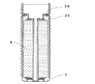
図1に示すように、本実施形態の円筒型リチウムイオン二次電池20は、有底円筒状で上側が電池蓋で封口された電池容器7及び帯状の正負極板がセパレータを介して断面渦巻状に捲回された電極群6を有している。
(Constitution)
As shown in FIG. 1, a cylindrical lithium ion
電池容器7の材質には鉄が用いられており、内部および外部の全面には非水電解液に不溶性のニッケルメッキが施されている。図2に示すように、電池容器7の表面には、可撓性を有するコート材がコートされることで被膜25が形成されている。コート材には、非水電解液に不溶性で電気絶縁性を有する、例えば、ブローンアスファルト等の有機化合物が使用されている。被膜25は、少なくとも電池蓋をカシメ固定する部分で、電池容器7の内面に形成されていればよいが、本例では、電池容器7の上端から電極群6の下端面に対応する位置までの内面および外面、並びに、電池容器7の上端面に形成されている。電池容器7の底部の内面および外面には被膜25が形成されず、ニッケルメッキが露出している。
Iron is used as the material of the
図1に示すように、電極群6の上側には、軸芯1のほぼ延長線上に正極板からの電位を集電するためのアルミニウム製の正極集電リング4が配置されている。正極集電リング4は、軸芯1の上端部に固定されている。正極集電リング4の周囲から一体に張り出している鍔部周縁には、正極板から導出された正極リード片2の端部が超音波溶接で接合されている。正極集電リング4の上方には、正極外部端子となる円盤状の電池蓋が配置されている。電池蓋は、アルミニウム製の蓋ケース12と、蓋キャップ13と、気密を保つ弁押え14と、内圧上昇により開裂する開裂弁11とで構成されており、これらが積層されて蓋ケース12の周縁をカシメ固定することで組立てられている。正極集電リング4の上部には複数枚のアルミニウム製リボンを重ね合わせて構成した2本の正極リード9のうち1本の一端が固定されており、蓋ケース12の下面には他の1本の一端が溶接されている。2本の正極リード9の他端同士は溶接で接合されている。
As shown in FIG. 1, on the upper side of the
一方、電極群6の下側には負極板からの電位を集電するための銅製の負極集電リング5が配置されている。負極集電リング5の内周面には軸芯1の下端部外周面が固定されている。負極集電リング5の外周縁には、負極板から導出された負極リード片3の端部が溶接で接合されている。負極集電リング5の下部には電気的導通のための銅製の負極リード板8が溶接されており、負極リード板8は電池容器7の内底面に溶接で接合されている。電池容器7の寸法は、本例では、高さ113.5mm、外径40mm、内径39mmに設定されている。
On the other hand, a copper negative electrode current collecting
電池蓋は、絶縁性及び耐熱性のEPDM樹脂製ガスケット10を介して電池容器7の上側にカシメ固定されている。このため、リチウムイオン二次電池20の内部は密封されており、電池容器7が負極外部端子を兼ね、電池蓋が正極外部端子を兼ねている。また、電池容器7内には、非水電解液が注液されている。非水電解液には、エチレンカーボネートとジメチルカーボネートとの体積比1:1の混合溶媒中にリチウム塩として6フッ化リン酸リチウム(LiPF6)を1モル/リットル溶解したものが用いられている。
The battery lid is caulked and fixed to the upper side of the
電極群6は、正極板と負極板とが、これら両極板が直接接触しないようにセパレータを介し、軸芯1の周囲(外側)に捲回されている。セパレータには、本例では、幅90.5mm、厚さ40μmの多孔質ポリエチレン製フィルムが使用されている。正極リード片2と負極リード片3とは、それぞれ電極群6の互いに反対側の両端面に配置されている。電極群6及び正極集電リング4の鍔部周面全周には、絶縁被覆が施されている。絶縁被覆には、ポリイミド製の基材の片面にヘキサメタアクリレートの粘着剤が塗布された粘着テープが用いられている。粘着テープは鍔部周面から電極群6の外周面に亘って一重以上巻かれている。正極板、負極板、セパレータの長さを調整することで、電極群6の直径が38±0.1mmに設定されている。
In the
電極群6を構成する負極板は、負極集電体として厚さ10μmの圧延銅箔を有している。圧延銅箔の両面には、負極活物質としてリチウムイオンを吸蔵、放出可能な非晶質炭素粉末を含む負極合剤が塗着されている。負極合剤には、例えば、非晶質炭素粉末の90重量部に対して、バインダ(結着材)のポリフッ化ビニリデン(以下、PVDFと略記する。)の10重量部が配合されている。圧延銅箔に負極合剤を塗着するときには、分散溶媒のN−メチル−2−ピロリドン(以下、NMPと略記する。)が用いられる。圧延銅箔の長寸方向一側の側縁には、幅30mmの負極合剤の未塗着部が形成されている。未塗着部は櫛状に切り欠かれており、切り欠き残部で負極リード片3が形成されている。隣り合う負極リード片3の間隔が50mm、負極リード片3の幅が5mmに設定されている。負極板は、乾燥後、厚さ70μmとなるように、加熱可能なロールプレス機でプレス加工され、幅88mmに裁断されている。
The negative electrode plate constituting the
一方、正極板は、正極集電体として厚さ20μmのアルミニウム箔を有している。アルミニウム箔の両面には、正極活物質としてリチウム遷移金属複酸化物を含む正極合剤が塗着されている。正極合剤には、例えば、リチウム遷移金属複酸化物の100重量部に対して、導電材の鱗片状黒鉛の10重量部及びバインダのPVDFの5重量部が配合されている。アルミニウム箔に正極合剤を塗着するときには、分散溶媒のNMPが用いられる。アルミニウム箔の長寸方向一側の側縁には、負極板と同様に幅30mmの正極合剤の未塗着部が形成されており、正極リード片2が形成されている。隣り合う正極リード片2の間隔が50mm、正極リード片2の幅が5mmに設定されている。正極板は、乾燥後、厚さ90μmとなるように、負極板と同様にプレス加工され、幅84mmに裁断されている。
On the other hand, the positive electrode plate has an aluminum foil having a thickness of 20 μm as a positive electrode current collector. A positive electrode mixture containing a lithium transition metal double oxide as a positive electrode active material is applied to both surfaces of the aluminum foil. In the positive electrode mixture, for example, 10 parts by weight of flaky graphite as a conductive material and 5 parts by weight of PVDF as a binder are blended with 100 parts by weight of lithium transition metal double oxide. When applying the positive electrode mixture to the aluminum foil, a dispersion solvent NMP is used. An uncoated portion of a positive electrode mixture with a width of 30 mm is formed on the side edge on one side in the longitudinal direction of the aluminum foil, and a positive
(電池組立)
リチウムイオン二次電池20の組立は以下の手順で行う。まず、電池容器7の表面にコート材をコートし被膜25を形成する(図2参照)。このとき、開口が形成された電池容器7の上端を下側にし上端から100mmの範囲をコート材の液中に浸漬した後乾燥するディップコート法を用いる。乾燥は、25°Cの真空状態で1日間行う。上端から100mmの範囲にコートすることで、皮膜25が電極群6の下端面に対応する位置まで形成される。一方、正負極板をセパレータを介して軸芯1の周囲に捲回装置で捲回し電極群6を作製し、電極群6の両端面からそれぞれ導出されている正極リード片2及び負極リード片3を正極集電リング4及び負極集電リング5にそれぞれ溶接する。図3に示すように、被膜25を形成した電池容器7内に電極群6を挿入し、負極集電リング5に予め溶接しておいた負極リード板8を電池容器7の内底面に溶接する。電池容器7の上端から9mm下方の位置の内側に、電池蓋を載せるための段付け部28を形成する段付け加工を施す。正極集電リング4及び電池蓋を正極リード板9で接続した後、電池容器7内に非水電解液を軸芯1の中空部分から注液して電極群6を非水電解液に浸潤させる。正極リード板9を折りたたむようにして電池容器7内に収容し、電池蓋を段付け部28に載せた後、段付け部28より上側で電池蓋をガスケット10を介してカシメ固定することで、リチウムイオン二次電池20の組立を完成させる。
(Battery assembly)
The lithium ion
次に、本実施形態のリチウムイオン二次電池20の作用等について説明する。
Next, the operation and the like of the lithium ion
本実施形態のリチウムイオン二次電池20では、ニッケルメッキが施された電池容器7の上端から電極群6の下端面に対応する位置までの内面に被膜25が形成されている。被膜25には、非水電解液に不溶性で可撓性を有する有機化合物のブローンアスファルトが用いられている。このため、電池容器7に段付け部28を形成するときや電池蓋をカシメ固定するときに、電池容器7の変形によりニッケルメッキにひび割れが生じて(割れて)も被膜25がひび割れを生じることなく変形し電池容器7の内面を被覆する。これにより、ニッケルメッキのひび割れが生じた部分で電池容器7の地金の鉄と非水電解液との接触が被膜25により妨げられるので、鉄が非水電解液に溶解せず鉄イオンの非水電解液中への溶出を防止することができる。また、皮膜25が非水電解液に不溶性のため、電池容器7の内面を長期間安定に被覆することができる。従って、リチウムイオン二次電池20を充放電しても、鉄の析出による正負極間の微小短絡が形成されず電池電圧の低下を抑制することができる。
In the lithium ion
また、被膜25が電極群6の下端面に対応する位置まで形成されているため、電池使用時等にリチウムイオン二次電池20の側面からの外力で電池容器7のニッケルメッキにひび割れが生じても、地金の鉄の溶解を防止することができる。これにより、外力による外観上の変形が認められない場合でも、鉄の析出に伴う微小短絡を防止し電池電圧の低下を抑制することができる。
Further, since the
更に、本実施形態のリチウムイオン二次電池20では、電池容器7の上端から電極群6の下端面に対応する位置までの外面にも被膜25が形成されている。被膜25は、電気絶縁性も有しているため、例えば、組電池を作製するときに、隣り合う2つのリチウムイオン二次電池20のうち、一方の電池の正極外部端子を兼ねる電池蓋と、他方の電池の負極外部端子を兼ねる電池容器7の側面とが接近しても、被膜25が介在するので、ショートの発生を防止することができる。これにより、不良電池の発生が減少するので、組電池作製の歩留りを向上させることができる。
Furthermore, in the lithium ion
また更に、本実施形態のリチウムイオン二次電池20では、電池容器7の上端面にも被膜25が形成されている。このため、電池蓋と、この電池蓋がカシメ固定された電池容器7の上端部との間に、ガスケット10に加えて被膜25が介在するので、リチウムイオン二次電池20の上面に金属が接触しても、正負極間の短絡を防止することができる。
Furthermore, in the lithium ion
従来リチウムイオン二次電池では、電池容器に用いられる鉄等の金属が非水電解液に溶解することを防ぐため、電池容器表面に非水電解液に不溶性のニッケル等でメッキが施されている。ところが、電池容器に電池蓋をカシメ固定するとき等に電池容器が変形するため、ニッケル等のメッキにひび割れが生じる。このひび割れが生じた部分で地金の鉄等が非水電解液と接触して溶解するため、鉄等の金属イオンを溶出する。溶出した金属イオンが電池の充放電に伴い負極表面に金属として析出し成長してデンドライトを形成するため、セパレータを貫通して正負極間の短絡を引き起こし、電池電圧の低下を招く。また、大型のリチウムイオン二次電池の場合には、複数のリチウムイオン二次電池を接続した組電池として販売されるため、組電池作製後に絶縁処理が施される。この場合、電池容器が負極外部端子を兼ねるリチウムイオン二次電池では、電池表面の大部分を電池容器が占めているため、正極外部端子を兼ねる電池蓋と電池容器とが接近することがある。このため、組電池作製中に個々の非水電解液二次電池が別の非水電解液二次電池や金属等に接触しショートしてしまうトラブルが発生するおそれがある。本実施形態は、これらの問題を解決するリチウムイオン二次電池である。 In conventional lithium ion secondary batteries, in order to prevent metals such as iron used for battery containers from dissolving in non-aqueous electrolyte, the surface of the battery container is plated with nickel that is insoluble in non-aqueous electrolyte. . However, since the battery container is deformed, for example, when the battery lid is caulked and fixed to the battery container, cracks occur in the plating of nickel or the like. Since the metal such as iron in contact with the non-aqueous electrolyte dissolves in the cracked portion, metal ions such as iron are eluted. The eluted metal ions are deposited as a metal on the negative electrode surface as the battery is charged and discharged and grow to form dendrites, causing a short circuit between the positive and negative electrodes through the separator, leading to a decrease in battery voltage. Moreover, in the case of a large-sized lithium ion secondary battery, since it is sold as an assembled battery in which a plurality of lithium ion secondary batteries are connected, insulation treatment is performed after the assembled battery is manufactured. In this case, in the lithium ion secondary battery in which the battery container also serves as the negative electrode external terminal, since the battery container occupies most of the battery surface, the battery lid that also serves as the positive electrode external terminal and the battery container may approach each other. For this reason, there is a possibility that a trouble may occur that an individual non-aqueous electrolyte secondary battery comes into contact with another non-aqueous electrolyte secondary battery, metal, or the like during a battery assembly and short-circuits. The present embodiment is a lithium ion secondary battery that solves these problems.
なお、本実施形態では、被膜25を形成するコート材に、非水電解液に不溶性で可撓性を有する有機化合物のブローンアスファルトを例示したが、本発明はこれに限定されるものではなく、可撓性を有していればよい。本実施形態以外で用いることができるコート材としては、ストレートアスファルト等のアスファルト、ポリプロピレン等のオレフィン樹脂等を挙げることができる。コート材に非水電解液に不溶性の材料を用いれば、電池容器からの金属イオンの溶出防止効果を長期間持続することができる。また、コート材に有機化合物を用いれば、可撓性や非水電解液に対する不溶性を有する皮膜25を容易に得ることができる。更に、コート材が絶縁性を有していれば、電池同士の接触や金属との接触等による不測の(不注意による)短絡発生を防止することができる。
In the present embodiment, the coating material for forming the
また、本実施形態では、被膜25を電池容器7の上端から電極群6の下端面に対応する位置までの内面および外面、並びに、電池容器7の上端面に形成する例を示したが、本発明はこれに限定されるものではない。被膜25が、少なくとも電池蓋をカシメ固定する部分の内面に形成されていればよく、これにより、段付け加工時やカシメ固定時のニッケルメッキのひび割れによる地金の溶解を防止することができる。皮膜25を電池容器7の内面の上端から内底面近傍まで形成しておけば、電池使用時の外力に対しても電池容器7の地金の溶解を防止することができる。また、皮膜25を電池容器7の外面の上端から底面近傍まで形成しておけば、電池同士の接触による短絡発生を防止することができ、電池容器7の上端面に形成しておけば、電池上面に金属が接触することによる短絡発生を防止することができる。
In the present embodiment, the
更に、本実施形態では、電池容器7にニッケルメッキを施した鉄を用いる例を示したが、本発明はこれに限定されるものではなく、金属製で非水電解液に不溶性の金属メッキが施された電池容器を使用することができる。本実施形態以外で使用することができる電池容器の地金としては、鉄と炭素とを含む炭素鋼、更にニッケルやクロムを含む特殊鋼等を挙げることができる。また、金属メッキとしては、ニッケル合金メッキ等を挙げることができる。
Furthermore, in this embodiment, the example which uses the iron which gave nickel plating to the
また更に、本実施形態では、被膜25の形成に、電池容器7をコート材の液中に浸漬することで、内面および外面を同じコート材で同時にコートするディップコート法を例示したが、本発明はこれに限定されるものではない。例えば、スプレ法等としてもよく、電池容器7にコート材を膜状に形成することができる方法であればよい。また、例えば、電池容器7の内面と外面とをそれぞれ異なるコート材で別々にコートしてもよい。
Furthermore, in the present embodiment, the dip coating method in which the inner surface and the outer surface are simultaneously coated with the same coating material by immersing the
更にまた、本実施形態では、円筒型リチウムイオン二次電池20を例示したが、本発明はこれに限定されるものではなく、非水電解液を用いる二次電池であれば適用することができる。また、電池形状についても制限はなく、例えば、角形や多角形であってもよい。更に、正極および負極がセパレータを介して捲回された電極群6以外に積層された電極群を用いてもよい。
Furthermore, in the present embodiment, the cylindrical lithium ion
次に、本実施形態に従い作製したリチウムイオン二次電池20の実施例について説明する。なお、比較のために作製した比較例のリチウムイオン二次電池についても併記する。
Next, examples of the lithium ion
(実施例1)
実施例1では、ニッケルメッキを施した鉄製で、内面および外面をブローンアスファルトでコートし被膜25を形成した電池容器7を用いて電池を作製した。コートは電池容器7の上端から100mmの範囲とした。被膜25の下端は、電極群6の下端面に対応する位置となる。
Example 1
In Example 1, a battery was fabricated using a
(比較例1)
比較例1では、ニッケルメッキを施した鉄製の電池容器を何もコートせずにそのまま用いた以外は実施例1と同様にした。従って、比較例1の電池は、従来のリチウムイオン二次電池である。
(Comparative Example 1)
Comparative Example 1 was the same as Example 1 except that the nickel-plated iron battery container was used as it was without coating. Therefore, the battery of Comparative Example 1 is a conventional lithium ion secondary battery.
(比較例2)
比較例2では、ニッケルメッキを施した鉄製で、内面および外面をシリカでコートしシリカ被膜を形成した電池容器を用いて電池を作製した。コート範囲は実施例1と同様に電池容器の上端から100mmとした。
(Comparative Example 2)
In Comparative Example 2, a battery was fabricated using a battery container made of nickel-plated iron and coated with silica on the inner and outer surfaces to form a silica coating. The coating range was set to 100 mm from the upper end of the battery container as in Example 1.
(比較例3)
比較例3では、ニッケルメッキを施した鉄製で、内面および外面を植物油でコートし植物油被膜を形成した電池容器を用いて電池を作製した。コート範囲は実施例1と同様に電池容器の上端から100mmとした。
(Comparative Example 3)
In Comparative Example 3, a battery was fabricated using a battery container made of nickel-plated iron and coated on the inner and outer surfaces with vegetable oil to form a vegetable oil film. The coating range was set to 100 mm from the upper end of the battery container as in Example 1.
<試験・評価>
1.鉄イオン溶出量の測定
実施例及び比較例の各電池について、充電をせずに1週間放置した後、電池蓋のアルミニウム部分にチタン製の棒を用いて穴を開け非水電解液をとりだし、ICP(Inductively Coupled Plasma)発光分析により非水電解液中の鉄イオン濃度を測定した。電池容器に注液する前の非水電解液中の鉄イオン濃度は0.1ppm以下であること、電池内部では電池容器以外に鉄を含む材料を使用していないことから、測定した鉄イオン濃度は電池容器から溶出した鉄イオン量に対応すると考えられる。鉄イオン濃度の測定結果を下表1に示す。
<Test and evaluation>
1. Measurement of iron ion elution amount For each battery of Examples and Comparative Examples, after leaving for one week without charging, a hole was made using a titanium rod in the aluminum part of the battery lid, and the non-aqueous electrolyte was taken out. The iron ion concentration in the non-aqueous electrolyte was measured by ICP (Inductively Coupled Plasma) emission analysis. The iron ion concentration in the non-aqueous electrolyte before pouring into the battery container is 0.1 ppm or less, and since the material containing iron other than the battery container is not used inside the battery, the measured iron ion concentration Corresponds to the amount of iron ions eluted from the battery container. The measurement results of the iron ion concentration are shown in Table 1 below.
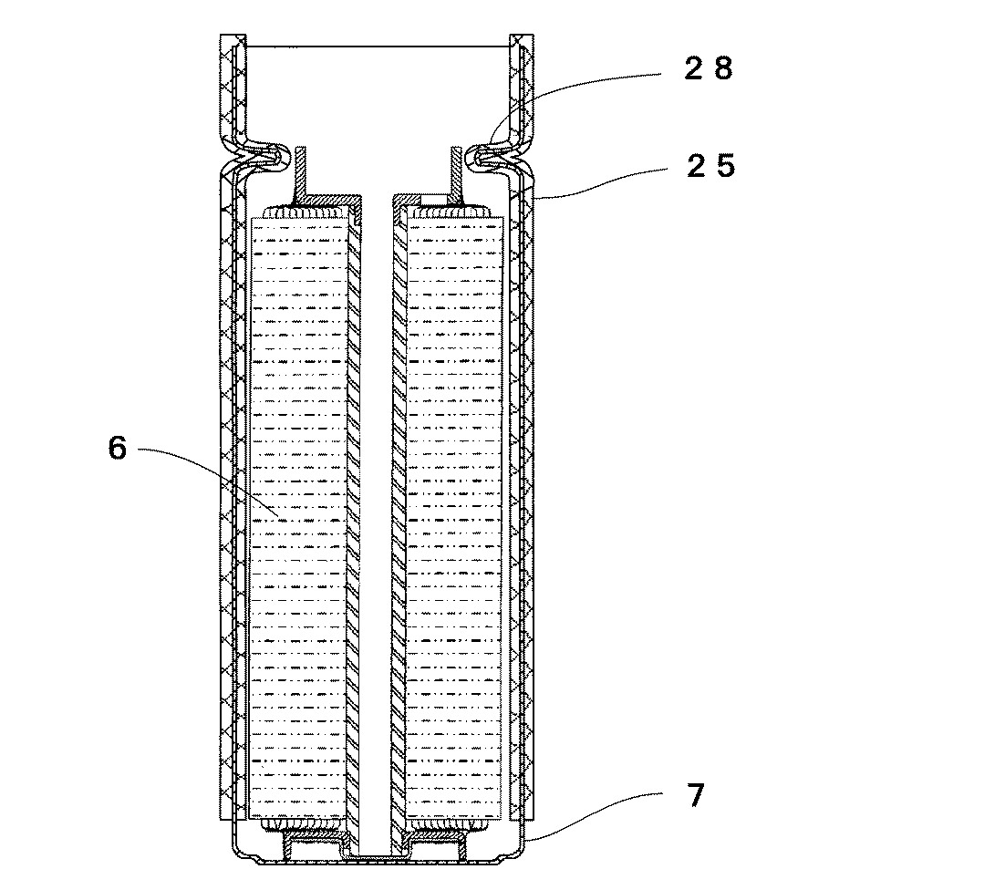
表1に示すように、コートしない電池容器を用いた比較例1のリチウムイオン二次電池では、ニッケルメッキが電池容器内部および外部の全面を覆っていたにもかかわらず、ニッケルメッキの地金である鉄が溶解し鉄イオンの溶出が認められている。電池を解体し調査したところ、電池蓋をカシメ固定した部分(以下、カシメ固定部という。)およびその近傍のニッケルメッキが一部割れていた。このため、ニッケルメッキが割れた部分で非水電解液が地金の鉄と接触し鉄イオンが溶出したと考えられる。また、シリカ被膜を形成した電池容器を用いた比較例2のリチウムイオン二次電池では、比較例1に比べて若干鉄イオンの溶出が抑制されているが、シリカ被膜では鉄イオンの溶出防止には大きな効果が確認されなかった。電池を解体し調査したところ、カシメ固定部の近傍でニッケルメッキと共にシリカ被膜の一部も割れていた。このことから、可撓性に乏しいシリカでコートしてもシリカ被膜が割れてしまうため、鉄イオンの溶出を防止することはできないと考えられる。更に、植物油被膜を形成した電池容器を用いた比較例3のリチウムイオン二次電池では、比較例1に比べて若干鉄イオンの溶出が抑制されているが、植物油被膜では鉄イオンの溶出防止には大きな効果が確認されなかった。電池を解体したところ、電池容器の内面に植物油被膜は存在していなかった。このことから、非水電解液に易溶な植物油でコートしても、植物油が非水電解液に溶解してしまうため、ニッケルメッキが割れた部分から鉄イオンが溶出したと考えられる。 As shown in Table 1, in the lithium ion secondary battery of Comparative Example 1 using an uncoated battery container, the nickel plating covered the entire surface inside and outside the battery container, but the nickel plating metal was used. Some iron is dissolved and iron ions are eluted. When the battery was disassembled and investigated, a portion where the battery cover was fixed by crimping (hereinafter referred to as a crimping fixing portion) and a portion of the nickel plating near the portion were cracked. For this reason, it is considered that the non-aqueous electrolyte contacted the iron of the metal at the part where the nickel plating was broken, and the iron ions were eluted. Further, in the lithium ion secondary battery of Comparative Example 2 using the battery container on which the silica coating is formed, the elution of iron ions is slightly suppressed as compared with Comparative Example 1, but the silica coating prevents the elution of iron ions. No significant effect was confirmed. When the battery was disassembled and investigated, a part of the silica coating was cracked along with the nickel plating in the vicinity of the caulking fixing portion. From this fact, it is considered that the elution of iron ions cannot be prevented because the silica coating is broken even when coated with silica having poor flexibility. Further, in the lithium ion secondary battery of Comparative Example 3 using the battery container in which the vegetable oil film is formed, the elution of iron ions is slightly suppressed as compared with Comparative Example 1, but the vegetable oil film prevents the elution of iron ions. No significant effect was confirmed. When the battery was disassembled, there was no vegetable oil film on the inner surface of the battery container. From this, even if it coats with vegetable oil which is easily soluble in nonaqueous electrolyte, since vegetable oil will dissolve in nonaqueous electrolyte, it is thought that iron ion eluted from the part which nickel plating broke.
これらの比較例に対して、ブローンアスファルトをコートし被膜25を形成した電池容器7を用いた実施例1のリチウムイオン二次電池20では、鉄イオンの溶出は確認されなかった。これは、段付け加工時やカシメ固定時に電池容器7の変形によりニッケルメッキが割れても、ニッケルメッキの上(内面)には非水電解液に不溶性で可撓性を有するブローンアスファルトの被膜25が形成されており、これが非水電解液と電池容器7の地金との接触を防いだためと考えられる。
For these comparative examples, elution of iron ions was not confirmed in the lithium ion
2.電池の電圧低下量の測定
実施例および比較例の電池各10本について、非水電解液を注液し密閉してから1週間放置した後、0.3Cの電流で4.1Vまで充電→1Cの電流で2.7Vまで放電→1Cの電流で3.7Vまで充電を行った。その後、温度22.5°Cで放置し、14日目電圧と21日目電圧とを測定した。測定した14日目電圧から21日目電圧を引いて電圧低下量を求め、電池10本の平均値を算出した。電圧低下量の測定結果を下表2に示す。
2. Measurement of battery voltage drop amount For each of the 10 batteries of the examples and comparative examples, the nonaqueous electrolyte was poured and sealed, left for 1 week, and then charged to 4.1 V with a current of 0.3 C → 1 C The battery was discharged to 2.7 V at a current of 1 to 3.7 V with a current of 1 C. Then, it was left at a temperature of 22.5 ° C., and the 14th day voltage and the 21st day voltage were measured. The voltage drop amount was calculated by subtracting the 21st day voltage from the measured 14th day voltage, and the average value of 10 batteries was calculated. The measurement results of the voltage drop amount are shown in Table 2 below.
表1、表2に示すように、鉄イオンの溶出量が多い電池ほど電圧低下量が大きいことが判った。電圧低下量の測定終了後、電池を解体してセパレータを取り出し観察したところ、鉄イオンの溶出量が大きい電池ほどセパレータが黒く変色していた。この黒く変色した部分の組成分析を実施した結果、鉄元素が観察された。このことから、電圧低下量の違いは、デンドライトの形成(成長)による微小短絡の箇所(発生数)の違いにより生じたと考えられる。従って、ニッケルメッキを施した鉄製電池容器の内面および外面を上端から電極群6の下端面に対応する位置までブローンアスファルトでコートすることで微小短絡が減少し電池電圧の低下を抑えることができることが判明した。
As shown in Tables 1 and 2, it was found that the voltage drop amount was larger for the battery with a larger amount of iron ion elution. After the measurement of the voltage drop amount was completed, the battery was disassembled, and the separator was taken out and observed. As a result, the battery with a larger iron ion elution amount was discolored black. As a result of the compositional analysis of the black-colored portion, iron element was observed. From this, it is considered that the difference in the amount of voltage drop was caused by the difference (number of occurrences) of the short circuit caused by the formation (growth) of dendrite. Therefore, by coating the inner and outer surfaces of the nickel-plated iron battery container with blown asphalt from the upper end to the position corresponding to the lower end surface of the
3.電池の短絡試験
実施例および比較例の各電池について、電池のプラス端子(電池蓋)と、ガスケットをはさんで近接する電池容器部分とを電気抵抗1mΩ以下の銅板に接触させ、短絡が発生するかを調査した。電池電圧は3.7Vとし、短絡は銅板に強く押し付けて実施した。短絡試験の結果を下表3に示す。
3. Battery short circuit test For each battery of the example and the comparative example, the positive terminal (battery cover) of the battery and the battery container part adjacent to the gasket are brought into contact with a copper plate having an electric resistance of 1 mΩ or less, and a short circuit occurs. I investigated. The battery voltage was 3.7 V, and the short circuit was performed by pressing strongly against the copper plate. The results of the short circuit test are shown in Table 3 below.
表3に示すように、比較例1のリチウムイオン二次電池では、電池蓋と電池容器とを銅板に接触させることで激しく短絡した。銅板を外して短絡箇所を観察したところ短絡痕が残っていた。一方、実施例1のリチウムイオン二次電池20および比較例2、比較例3のリチウムイオン二次電池では、短絡が発生しなかった。これは、ニッケルメッキを施した電池容器の表面に絶縁性を有するコート材がコートされている(被膜が存在する)ことにより電池容器と電池蓋とが直接接触せず電気的に絶縁されたためと考えられる。従って、電池蓋をカシメ固定したときにプラス端子近傍に位置すると想定される電池容器部分に絶縁性の被膜を形成しておき、その電池容器に電池蓋をカシメ固定することで短絡を防止することができることが判明した。
As shown in Table 3, the lithium ion secondary battery of Comparative Example 1 was severely short-circuited by bringing the battery lid and battery container into contact with the copper plate. When the copper plate was removed and the short-circuited portion was observed, short-circuit traces remained. On the other hand, in the lithium ion
本発明は金属製電池容器の溶解による電池電圧の低下を抑制することができる非水電解液二次電池を提供するため、非水電解液二次電池の製造、販売に寄与するので、産業上の利用可能性を有する。 The present invention provides a non-aqueous electrolyte secondary battery that can suppress a decrease in battery voltage due to dissolution of a metal battery container, and therefore contributes to the manufacture and sale of non-aqueous electrolyte secondary batteries. With the availability of
3 負極リード片
5 負極集電リング
6 電極群
7 電池容器
20 円筒型リチウムイオン二次電池
25 被膜
28 段付け部
DESCRIPTION OF
Claims (7)
Priority Applications (1)
| Application Number | Priority Date | Filing Date | Title |
|---|---|---|---|
| JP2005247016A JP4875868B2 (en) | 2005-08-29 | 2005-08-29 | Non-aqueous electrolyte secondary battery |
Applications Claiming Priority (1)
| Application Number | Priority Date | Filing Date | Title |
|---|---|---|---|
| JP2005247016A JP4875868B2 (en) | 2005-08-29 | 2005-08-29 | Non-aqueous electrolyte secondary battery |
Publications (2)
| Publication Number | Publication Date |
|---|---|
| JP2007066530A JP2007066530A (en) | 2007-03-15 |
| JP4875868B2 true JP4875868B2 (en) | 2012-02-15 |
Family
ID=37928507
Family Applications (1)
| Application Number | Title | Priority Date | Filing Date |
|---|---|---|---|
| JP2005247016A Expired - Fee Related JP4875868B2 (en) | 2005-08-29 | 2005-08-29 | Non-aqueous electrolyte secondary battery |
Country Status (1)
| Country | Link |
|---|---|
| JP (1) | JP4875868B2 (en) |
Families Citing this family (3)
| Publication number | Priority date | Publication date | Assignee | Title |
|---|---|---|---|---|
| JP5245858B2 (en) * | 2009-01-21 | 2013-07-24 | 新日鐵住金株式会社 | Metal outer case and non-aqueous secondary battery for non-aqueous secondary battery with little capacity drop due to charge / discharge cycle |
| US20120009464A1 (en) | 2009-03-31 | 2012-01-12 | Makoto Nakazawa | Material for metal case of secondary battery using non-aqueous electrolyte, metal case, secondary battery, and producing method of material for metal case |
| CN103050731A (en) * | 2012-12-18 | 2013-04-17 | 天津力神电池股份有限公司 | Preparation method for insulating coating of lithium ion battery case and lithium ion battery |
Family Cites Families (4)
| Publication number | Priority date | Publication date | Assignee | Title |
|---|---|---|---|---|
| JPH0963549A (en) * | 1995-08-28 | 1997-03-07 | Furukawa Battery Co Ltd:The | Lithium secondary battery |
| JPH1021888A (en) * | 1996-06-28 | 1998-01-23 | Nippon Polyurethane Ind Co Ltd | Insulating battery outer can and battery using the same |
| JPH10294093A (en) * | 1997-04-17 | 1998-11-04 | Mitsubishi Cable Ind Ltd | Insulation structure of sealed battery |
| JPH11273738A (en) * | 1998-03-19 | 1999-10-08 | Sony Corp | Non-aqueous electrolyte secondary battery |
-
2005
- 2005-08-29 JP JP2005247016A patent/JP4875868B2/en not_active Expired - Fee Related
Also Published As
| Publication number | Publication date |
|---|---|
| JP2007066530A (en) | 2007-03-15 |
Similar Documents
| Publication | Publication Date | Title |
|---|---|---|
| US12191533B2 (en) | Secondary battery | |
| EP3477729B2 (en) | Rechargeable lithium ion button cell battery | |
| CN101141009B (en) | Assembled battery | |
| JP6047583B2 (en) | Jelly roll type electrode assembly coated with active material and secondary battery having the same | |
| CN102142582B (en) | Sealed battery cell and method of manufacturing the same | |
| JPWO2011001639A1 (en) | Nonaqueous electrolyte secondary battery | |
| US20230223551A1 (en) | Lithium-ion cell with a high energy density | |
| CN109891640A (en) | Electrode for nonaqueous electrolyte secondary battery and non-aqueous electrolyte secondary battery | |
| JP2010003696A (en) | Electrode tab, and lithium secondary battery including it | |
| WO2007145275A1 (en) | Nonaqueous electrolyte secondary battery | |
| US8337572B2 (en) | Battery and method for producing the same | |
| CN111987379A (en) | Lithium ion battery with reference electrode and preparation method thereof | |
| JP5006603B2 (en) | Nonaqueous electrolyte secondary battery | |
| CN119096396A (en) | Energy storage battery cell and manufacturing method | |
| CN109891639A (en) | Electrode for nonaqueous electrolyte secondary battery and non-aqueous electrolyte secondary battery | |
| JP4688688B2 (en) | Secondary battery for large current discharge | |
| CN118104044A (en) | Energy storage battery cell, composite body made of energy storage battery cell and manufacturing method | |
| JP4875868B2 (en) | Non-aqueous electrolyte secondary battery | |
| KR101833609B1 (en) | Method of manufacturing electric power storage device, and electric power storage device | |
| KR20080016047A (en) | Secondary battery | |
| JPH09171809A (en) | Laser sealing battery | |
| US20230291080A1 (en) | Energy storage cell and production method | |
| JP2007087704A (en) | Nonaqueous electrolyte secondary battery | |
| JP2004296251A (en) | Non-aqueous electrolyte secondary battery | |
| US20240283100A1 (en) | Energy storage element, assembly of energy storage elements and production process |
Legal Events
| Date | Code | Title | Description |
|---|---|---|---|
| A621 | Written request for application examination |
Free format text: JAPANESE INTERMEDIATE CODE: A621 Effective date: 20070720 |
|
| A977 | Report on retrieval |
Free format text: JAPANESE INTERMEDIATE CODE: A971007 Effective date: 20110127 |
|
| A131 | Notification of reasons for refusal |
Free format text: JAPANESE INTERMEDIATE CODE: A131 Effective date: 20110215 |
|
| A521 | Request for written amendment filed |
Free format text: JAPANESE INTERMEDIATE CODE: A523 Effective date: 20110415 |
|
| TRDD | Decision of grant or rejection written | ||
| A01 | Written decision to grant a patent or to grant a registration (utility model) |
Free format text: JAPANESE INTERMEDIATE CODE: A01 Effective date: 20111115 |
|
| A01 | Written decision to grant a patent or to grant a registration (utility model) |
Free format text: JAPANESE INTERMEDIATE CODE: A01 |
|
| A61 | First payment of annual fees (during grant procedure) |
Free format text: JAPANESE INTERMEDIATE CODE: A61 Effective date: 20111128 |
|
| FPAY | Renewal fee payment (event date is renewal date of database) |
Free format text: PAYMENT UNTIL: 20141202 Year of fee payment: 3 |
|
| R150 | Certificate of patent or registration of utility model |
Free format text: JAPANESE INTERMEDIATE CODE: R150 |
|
| S111 | Request for change of ownership or part of ownership |
Free format text: JAPANESE INTERMEDIATE CODE: R313111 |
|
| R350 | Written notification of registration of transfer |
Free format text: JAPANESE INTERMEDIATE CODE: R350 |
|
| LAPS | Cancellation because of no payment of annual fees |