JP4880933B2 - 選択的な動作装置 - Google Patents
選択的な動作装置 Download PDFInfo
- Publication number
- JP4880933B2 JP4880933B2 JP2005210041A JP2005210041A JP4880933B2 JP 4880933 B2 JP4880933 B2 JP 4880933B2 JP 2005210041 A JP2005210041 A JP 2005210041A JP 2005210041 A JP2005210041 A JP 2005210041A JP 4880933 B2 JP4880933 B2 JP 4880933B2
- Authority
- JP
- Japan
- Prior art keywords
- operating
- rotating element
- group
- mode
- operating device
- Prior art date
- Legal status (The legal status is an assumption and is not a legal conclusion. Google has not performed a legal analysis and makes no representation as to the accuracy of the status listed.)
- Expired - Lifetime
Links
Images



Classifications
-
- B—PERFORMING OPERATIONS; TRANSPORTING
- B60—VEHICLES IN GENERAL
- B60G—VEHICLE SUSPENSION ARRANGEMENTS
- B60G21/00—Interconnection systems for two or more resiliently-suspended wheels, e.g. for stabilising a vehicle body with respect to acceleration, deceleration or centrifugal forces
- B60G21/02—Interconnection systems for two or more resiliently-suspended wheels, e.g. for stabilising a vehicle body with respect to acceleration, deceleration or centrifugal forces permanently interconnected
- B60G21/06—Interconnection systems for two or more resiliently-suspended wheels, e.g. for stabilising a vehicle body with respect to acceleration, deceleration or centrifugal forces permanently interconnected fluid
-
- B—PERFORMING OPERATIONS; TRANSPORTING
- B60—VEHICLES IN GENERAL
- B60G—VEHICLE SUSPENSION ARRANGEMENTS
- B60G21/00—Interconnection systems for two or more resiliently-suspended wheels, e.g. for stabilising a vehicle body with respect to acceleration, deceleration or centrifugal forces
- B60G21/02—Interconnection systems for two or more resiliently-suspended wheels, e.g. for stabilising a vehicle body with respect to acceleration, deceleration or centrifugal forces permanently interconnected
- B60G21/04—Interconnection systems for two or more resiliently-suspended wheels, e.g. for stabilising a vehicle body with respect to acceleration, deceleration or centrifugal forces permanently interconnected mechanically
- B60G21/05—Interconnection systems for two or more resiliently-suspended wheels, e.g. for stabilising a vehicle body with respect to acceleration, deceleration or centrifugal forces permanently interconnected mechanically between wheels on the same axle but on different sides of the vehicle, i.e. the left and right wheel suspensions being interconnected
-
- B—PERFORMING OPERATIONS; TRANSPORTING
- B60—VEHICLES IN GENERAL
- B60T—VEHICLE BRAKE CONTROL SYSTEMS OR PARTS THEREOF; BRAKE CONTROL SYSTEMS OR PARTS THEREOF, IN GENERAL; ARRANGEMENT OF BRAKING ELEMENTS ON VEHICLES IN GENERAL; PORTABLE DEVICES FOR PREVENTING UNWANTED MOVEMENT OF VEHICLES; VEHICLE MODIFICATIONS TO FACILITATE COOLING OF BRAKES
- B60T13/00—Transmitting braking action from initiating means to ultimate brake actuator with power assistance or drive; Brake systems incorporating such transmitting means, e.g. air-pressure brake systems
- B60T13/10—Transmitting braking action from initiating means to ultimate brake actuator with power assistance or drive; Brake systems incorporating such transmitting means, e.g. air-pressure brake systems with fluid assistance, drive, or release
- B60T13/12—Transmitting braking action from initiating means to ultimate brake actuator with power assistance or drive; Brake systems incorporating such transmitting means, e.g. air-pressure brake systems with fluid assistance, drive, or release the fluid being liquid
- B60T13/16—Transmitting braking action from initiating means to ultimate brake actuator with power assistance or drive; Brake systems incorporating such transmitting means, e.g. air-pressure brake systems with fluid assistance, drive, or release the fluid being liquid using pumps directly, i.e. without interposition of accumulators or reservoirs
- B60T13/168—Arrangements for pressure supply
Landscapes
- Engineering & Computer Science (AREA)
- Mechanical Engineering (AREA)
- Transportation (AREA)
- Regulating Braking Force (AREA)
- Vehicle Body Suspensions (AREA)
- Gear-Shifting Mechanisms (AREA)
- Mechanical Control Devices (AREA)
- Braking Arrangements (AREA)
- Switches With Compound Operations (AREA)
- Accommodation For Nursing Or Treatment Tables (AREA)
- Lock And Its Accessories (AREA)
- Seal Device For Vehicle (AREA)
- Fluid-Damping Devices (AREA)
- Valve Device For Special Equipments (AREA)
- Glass Compositions (AREA)
Description
そうしたモデルとしては、例えば、2輪の前輪ステアリングを備えた3輪自動車や、QUADとして知られている4輪自動車がある。
実際に、例えば駐車中や信号停止などの一時的な停止時など、ある種の運転状態中に、バランスを失なって運転者が落下することを防ぐべく、車輪のブレーキだけでなく、サスペンションのストロークを遮断することが可能である。
こうした観点から、自動的に及びユーザの様々な要望に応じて、後輪のパーキングブレーキや、サスペンションのストロークのストッパ装置、及びアンチロールシステムなど、様々な操作グループの結合及び/又は切り離しを制御することができるような、選択的な動作装置を設けることが必要であることは明らかである。
本発明の別の目的は、簡単で安価に生産できるような、選択的な動作装置を提供することである。
実質的には、本発明による選択的な動作装置は、少なくともひとつのアクチュータを備えたタイプのものであって、該アクチュータが動作機構を動作させる。後者つまり動作機構は、第1の操作グループを動作させるための少なくともひとつの押込要素と、回転要素とを備え、該回転要素は、第2の操作グループに対して作用するような動作時モードと、第1の操作グループの動作が第2の操作グループから切り離されるような休止時モードとの間にて動くようになっている。
本発明に関するさらに別の特徴及び利点については、限定的な意図はなく、あくまでも例示を提供するものである、以下の詳細な説明及び添付図面によって明らかになるだろう。
以下の説明においては、発明をより良く理解できるようにするため、2輪の前輪ステアリングと1輪の後輪とを備えた、3輪自動車におけるローリングの用途について説明する。
特に、選択的な動作装置は、ユーザの要望に応じて、1又は複数の操作グループの動作又は不動作を同時に制御することが可能である。
サスペンションのストロークのストッパ装置と、上述したタイプのアンチロールシステム用のストッパ装置とについては、例えば、本願出願人によるITMI2004A000172号とITMI2004A000171号との出願にそれぞれ開示されている。
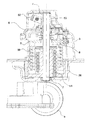
図面に示した好ましい実施形態によれば、動作装置1は、動作機構2に対して作用するようなアクチュータ5を備えている。そうした機構2は、第1の操作グループ12及び13を動作させるための押込要素8と、回転要素53とを備えている。回転要素53は、車両の後輪のパーキングブレーキを動作させる第2の操作グループに対して作用するような動作時モードと、第1の操作グループ12及び13の動作が第2の操作グループから切り離されるような休止時モードとの間にて動く。動作装置1はさらに、図2及び図5に示す如く、押込要素8とアクチュータ5との間に介在されてなる、少なくともひとつの弾性手段50及び51を備え、動作装置を常にチャージ状態に維持する。
このため、弾性手段は、押込要素8とシャフト7とを動作させる役目をもった、少なくとも一対の螺旋状バネ50及び51を備えていて、これらは回転要素53が動作したとき、第2の操作グループ6,9,10に機能的に結合される。
第1の操作グループは、前述の如く、油ポンプ12によって代表され、該ポンプが液圧回路13に対して作用すると、アンチロールシステムにおける遮断装置3と、フロントサスペンションのストロークのストッパ装置14及び14’とが動作する。
螺旋状バネ50は、その一端は歯付きセクタ26に、他端は押込要素8に、しっかりと保持されている。
他方において、バネ51は、その一端を歯付きセクタ26にしっかりと保持され、他端はシャフト7に保持されて、該シャフトはこれと一体的に歯付き要素53を支持している。
上述の如く、歯付き要素53は、可動であるという特性を有していて、もって“動作時モード”に挿入され、または、“休止時モード”に取り外されることができる。
シャフト7と一体をなす歯付き要素53が動作すると、該要素53は要素6に対して“係合”することができ、シャフト7の回転によって、後輪のブレーキケーブル9を動作させることが可能になる。後輪のブレーキケーブル9は、後輪のパーキングブレーキのブレーキ要素10に作用して、車両の後輪を止める。
言い換えれば、動作時モードにおいては、歯付き要素53は、図2に示す如く、要素6と一体的になって、これがシャフト7の回転によって回転すると、要素6が動いて、車両の後輪にブレーキをかける。
歯付き要素53はまた、休止状態をも有することを既述したが、この状態は、後輪のブレーキ動作を排除すべく働くものである(例えばアンチロールシステムを動作させつつ車両を運転する場合など)。かかる状態にするためには、解放レバー要素52を動作させ、該レバーが動作すると、シャフト7を“持ち上げ”、歯付き要素53は、もはや要素6に対して係合しなくなる。
しかしながら、如何なる場合においても、不図示の手動又はフットレバーのいずれかによる公知の仕方の後輪のブレーキの動作は、またポンプ12の動作を含意しないことに留意されたい。
そして、解放レバー52は、レバーやボタン又はその他のユーザによって直接操作されるコントローラなど、不図示の特別な制御手段によって、歯付き要素53の状態を制御すべく動作する。
本発明について、好ましい実施形態に従った限定的な意味ではなく、例示的な目的において開示したけれども、特許請求の範囲に定められた保護範囲を逸脱することなく、当業者は、改良及び/又は変形を行うことが可能であることを理解されたい。
2 動作機構
5 アクチュータ
6 要素
7 シャフト
8 押込要素
9,10 第2の操作グループ
12,13 第1の操作グループ
24 駆動軸
26 歯付きセクタ
50,51 螺旋状バネ
52 解放レバー
53 回転要素
54 レバー
55,56 マイクロスイッチ
Claims (9)
- 動作機構(2)に作用する少なくともひとつのアクチュータ(5)を備えている、車両の1つ或いは2つ以上の操作グループ(9,10;12,13)を同時に動作させ又は動作させないための動作装置(1)であって、この動作装置が、第1の操作グループ(12,13)を動作させるための少なくともひとつの押込要素(8)と、回転要素(53)とを備え、該回転要素(53)は、該回転要素が第2の操作グループ(9,10)に対して作用するような動作時モードと、前記第1の操作グループ(12,13)の動作が前記第2の操作グループ(9,10)から切り離されるような休止時モードとを、前記回転要素(53)の移動によって選択できるようになっていて、この動作装置が、前記押込要素(8)と前記少なくともひとつのアクチュータ(5)との間に介在されてなる、少なくとも1つの弾性手段(50,51)を備え、前記動作装置(1)の構成要素の初期慣性を低減させるようになっており、前記アクチュータ(5)は、駆動軸(24)と歯付きピニオン(25)とを介して、歯付きセクタ(26)に対して作用し、
前記少なくとも1つの弾性手段は、前記押込要素(8)とシャフト(7)とを動作させる役目をもち、前記歯付きセクタ(26)が作用する少なくとも一対の第1螺旋状バネ(50)及び第2螺旋状バネ(51)を備え、前記歯付きセクタ(26)は、第1螺旋状バネ(50)によってしっかりと保持されて、前記押込要素(8)を介して前記第1の操作グループ(12,13)に動きを伝達し、且つ、第2螺旋状バネ(51)によってしっかりと保持されて、前記回転要素(53)が動作時モードにあるとき、前記シャフト(7)を介して前記回転要素(53)に動きを伝達し、前記第2の操作グループ(9,10)を動作させるようになっていることを特徴とする動作装置。 - 動作装置(1)において、前記第1の操作グループ(12,13)は、前記車両のアンチロールシステムにおける少なくともひとつの遮断装置(3)に対して作用する、液圧回路(13)に結合されたポンプ(12)を備えていることを特徴とする請求項1に記載の動作装置。
- 前記第2の操作グループ(9,10)は、車両の後輪のパーキングブレーキのための、少なくともケーブル(9)とブレーキ要素(10)とを備えていることを特徴とする請求項1又は2に記載の動作装置。
- 前記動作時モードにおいて、前記回転要素(53)は、前記第2の操作グループ(9,10)に作用すべく該回転要素に対応した係合要素(6)に対して結合することを特徴とする請求項1乃至3のいずれか一項に記載の動作装置。
- 前記回転要素(53)は、前記係合要素(6)における対応する歯に対して、前記動作時モードにおいて、結合するようになっている歯を備えていることを特徴とする請求項4に記載の動作装置。
- 前記回転要素(53)は、解放レバー(52)によって、前記動作時モードから前記休止時モードへと動かされることを特徴とする請求項1乃至5のいずれか一項に記載の動作装置。
- 前記解放レバー(52)は、前記車両の使用者によって直接に作動される制御手段によって、前記回転要素(53)の位置を制御すべく動作することを特徴とする請求項6に記載の動作装置。
- 前記制御手段は、レバー、ボタン、又はフットコントローラから構成されていることを特徴とする請求項7に記載の動作装置。
- 前記シャフト(7)はレバー(54)を動作させ、少なくとも2つのマイクロスイッチ(55,56)を動作させて、マイクロスイッチ(55,56)が、前記動作装置が“休止時モード”である旨の信号を制御スイッチ盤に送ることを特徴とする請求項1乃至8のいずれか一項に記載の動作装置。
Applications Claiming Priority (2)
| Application Number | Priority Date | Filing Date | Title |
|---|---|---|---|
| IT001452A ITMI20041452A1 (it) | 2004-07-20 | 2004-07-20 | Dispositivo di azionamento selettivo |
| ITMI2004A001452 | 2004-07-20 |
Publications (2)
| Publication Number | Publication Date |
|---|---|
| JP2006027607A JP2006027607A (ja) | 2006-02-02 |
| JP4880933B2 true JP4880933B2 (ja) | 2012-02-22 |
Family
ID=35241133
Family Applications (1)
| Application Number | Title | Priority Date | Filing Date |
|---|---|---|---|
| JP2005210041A Expired - Lifetime JP4880933B2 (ja) | 2004-07-20 | 2005-07-20 | 選択的な動作装置 |
Country Status (9)
| Country | Link |
|---|---|
| US (1) | US7334667B2 (ja) |
| EP (1) | EP1619097B1 (ja) |
| JP (1) | JP4880933B2 (ja) |
| CN (1) | CN1724299B (ja) |
| AT (1) | ATE472450T1 (ja) |
| DE (1) | DE602005022019D1 (ja) |
| ES (1) | ES2348139T3 (ja) |
| IT (1) | ITMI20041452A1 (ja) |
| TW (1) | TWI355460B (ja) |
Families Citing this family (3)
| Publication number | Priority date | Publication date | Assignee | Title |
|---|---|---|---|---|
| US8725520B2 (en) | 2007-09-07 | 2014-05-13 | Qualcomm Incorporated | Power efficient batch-frame audio decoding apparatus, system and method |
| US8071205B2 (en) * | 2008-07-31 | 2011-12-06 | Toray Industries, Inc. | Prepreg, preform, molded product, and method for manufacturing prepreg |
| CN101905694B (zh) * | 2009-06-04 | 2012-12-26 | 品秀橡胶股份有限公司 | 智能型电子可自动调整气压式悬吊系统 |
Family Cites Families (24)
| Publication number | Priority date | Publication date | Assignee | Title |
|---|---|---|---|---|
| IN161423B (ja) * | 1983-06-17 | 1987-11-28 | Westinghouse Brake & Signal | |
| JPS6120494U (ja) * | 1984-07-11 | 1986-02-06 | 本田技研工業株式会社 | 車両のパ−キングレバ装置 |
| GB8509022D0 (en) * | 1985-04-09 | 1985-05-15 | Hobson K | Anti-roll back device |
| JPS6361621A (ja) * | 1986-09-02 | 1988-03-17 | Hitachi Constr Mach Co Ltd | 作業車両のラムロツク制御装置 |
| US4923055A (en) * | 1989-01-24 | 1990-05-08 | Delaware Capital Formation, Inc. | Safety mechanism for preventing unintended motion in traction elevators |
| US5092432A (en) * | 1990-11-30 | 1992-03-03 | Allied-Signal Inc. | Mechanical energy storage for vehicle parking brakes |
| US5180038A (en) * | 1992-01-24 | 1993-01-19 | Orscheln Co. | Electronically controlled parking brake system |
| WO1997002963A2 (de) | 1995-07-12 | 1997-01-30 | Luk Getriebe-Systeme Gmbh | Kupplungs- und getriebebetätigungsvorrichtung |
| DE19822667A1 (de) | 1997-05-30 | 1998-12-03 | Luk Getriebe Systeme Gmbh | Vorrichtung zum Betätigen eines automatisierten Schaltgetriebes |
| DE19857714B4 (de) | 1997-12-23 | 2009-02-19 | Aft Atlas Fahrzeugtechnik Gmbh | Getriebe |
| US6459182B1 (en) * | 1998-05-14 | 2002-10-01 | Sew-Eurodrive Gmbh | Electric motor with brake |
| DE19945702A1 (de) * | 1999-09-23 | 2001-04-19 | Knorr Bremse Systeme | Zuspannvorrichtung für eine Fahrzeugbremse |
| DE19945701A1 (de) * | 1999-09-23 | 2001-04-19 | Knorr Bremse Systeme | Bremsaktuator |
| IT1314619B1 (it) | 2000-04-11 | 2002-12-20 | Automac Sas Di Bigi Ing Mauriz | Attuatori elettrici, per il comando della frizione e/o del cambiosequenziale nei veicoli a motore. |
| IT1317529B1 (it) * | 2000-05-16 | 2003-07-09 | Piaggio & C Spa | Veicolo a tre ruote con due ruote anteriori sterzanti |
| DE10058925B4 (de) * | 2000-11-28 | 2006-06-01 | Knorr-Bremse Systeme für Schienenfahrzeuge GmbH | Bremsaktuator |
| PT1363794E (pt) * | 2001-02-27 | 2006-10-31 | Aprilia Spa | Veiculo de tres rodas com sistema de suspensao basculante |
| US6609595B2 (en) * | 2001-10-09 | 2003-08-26 | Dura Global Technologies, Inc. | Electric parking brake with direct tension feedback |
| US6598885B2 (en) * | 2001-10-23 | 2003-07-29 | Liquidspring Technologies, Inc. | Single valve control of damping and stiffness in a liquid spring system |
| SE0104279D0 (en) * | 2001-12-18 | 2001-12-18 | Haldex Brake Prod Ab | A parking brake arrangement in an electrically operated brake |
| FR2834391B1 (fr) * | 2001-12-28 | 2004-04-02 | Somfy | Dispositif de frein a disques et de transmission de couple |
| ITMI20040171A1 (it) * | 2004-02-04 | 2004-05-04 | Piaggio & C Spa | Dispositivo anti-rollio per veicoli |
| ITMI20040173A1 (it) | 2004-02-04 | 2004-05-04 | Piaggio & C Spa | Dispositivo di azionamento selettivo |
| ITMI20040172A1 (it) | 2004-02-04 | 2004-05-04 | Piaggio & C Spa | Dispositivo di arresto corsa delle sospensioni di un veicolo |
-
2004
- 2004-07-20 IT IT001452A patent/ITMI20041452A1/it unknown
-
2005
- 2005-07-11 EP EP05106297A patent/EP1619097B1/en not_active Expired - Lifetime
- 2005-07-11 AT AT05106297T patent/ATE472450T1/de active
- 2005-07-11 DE DE602005022019T patent/DE602005022019D1/de not_active Expired - Lifetime
- 2005-07-11 ES ES05106297T patent/ES2348139T3/es not_active Expired - Lifetime
- 2005-07-15 US US11/182,644 patent/US7334667B2/en not_active Expired - Lifetime
- 2005-07-15 TW TW094124064A patent/TWI355460B/zh not_active IP Right Cessation
- 2005-07-20 CN CN200510085978.3A patent/CN1724299B/zh not_active Expired - Lifetime
- 2005-07-20 JP JP2005210041A patent/JP4880933B2/ja not_active Expired - Lifetime
Also Published As
| Publication number | Publication date |
|---|---|
| US7334667B2 (en) | 2008-02-26 |
| JP2006027607A (ja) | 2006-02-02 |
| ITMI20041452A1 (it) | 2004-10-20 |
| US20060017318A1 (en) | 2006-01-26 |
| TW200606352A (en) | 2006-02-16 |
| TWI355460B (en) | 2012-01-01 |
| ES2348139T3 (es) | 2010-11-30 |
| EP1619097A2 (en) | 2006-01-25 |
| ATE472450T1 (de) | 2010-07-15 |
| CN1724299B (zh) | 2010-09-08 |
| DE602005022019D1 (de) | 2010-08-12 |
| EP1619097B1 (en) | 2010-06-30 |
| EP1619097A3 (en) | 2007-09-26 |
| CN1724299A (zh) | 2006-01-25 |
Similar Documents
| Publication | Publication Date | Title |
|---|---|---|
| CN101568455B (zh) | 车辆用控制装置 | |
| JP4912670B2 (ja) | 電動ブレーキシステム | |
| JP5881251B2 (ja) | 車両制御装置 | |
| JP5334973B2 (ja) | 自動車に搭載される自動駐車ブレーキ装置の解除を制御するシステム | |
| JP2004513829A (ja) | ワイヤステアリング式操舵装置のためのクラッチ | |
| EP3727968A1 (en) | Brake-by-wire braking system for vehicles | |
| JP7185040B2 (ja) | 車両用のパーキングブレーキを制御するための方法および制御装置、ならびに車両用のパーキングブレーキシステム | |
| KR20120060394A (ko) | 차량용 전자제어유닛 및 그 제어방법 | |
| CN216861429U (zh) | 一种无人驾驶汽车双向推进式电子机械制动装置 | |
| US10933855B2 (en) | Drift mode for electronic handbrake | |
| CN100503329C (zh) | 一种防止车辆上坡起步后退的装置及方法 | |
| JP2006027607A (ja) | 選択的な動作装置 | |
| JP2005525967A (ja) | 常用ブレーキシステム及びパーキングブレーキシステムを備える車両ブレーキシステム | |
| JP2006231954A (ja) | 電動ブレーキ装置 | |
| JP3777525B2 (ja) | 制動力制御装置 | |
| EP1562098B1 (en) | Selective actuation device | |
| JP7240920B2 (ja) | 電動ブレーキ装置 | |
| KR100928220B1 (ko) | 전자식 주차 브레이크 시스템 | |
| KR100599311B1 (ko) | 듀얼 타입의 전자식 주차 브레이크 시스템 | |
| US12479407B2 (en) | Reverse assist system for saddle riding vehicle and method thereof | |
| EP1604844B1 (en) | Electronic control system for vehicle operating units | |
| JP2714637B2 (ja) | 自動車用ブレ−キ装置 | |
| KR20240115628A (ko) | 차량의 전자식 브레이크 장치 | |
| CN204383708U (zh) | 防抱死装置及其执行单元以及车辆 | |
| CN118274121A (zh) | 用于电子机械制动系统的双向驻车装置及控制方法 |
Legal Events
| Date | Code | Title | Description |
|---|---|---|---|
| A621 | Written request for application examination |
Free format text: JAPANESE INTERMEDIATE CODE: A621 Effective date: 20080716 |
|
| A131 | Notification of reasons for refusal |
Free format text: JAPANESE INTERMEDIATE CODE: A131 Effective date: 20101012 |
|
| A601 | Written request for extension of time |
Free format text: JAPANESE INTERMEDIATE CODE: A601 Effective date: 20101224 |
|
| A602 | Written permission of extension of time |
Free format text: JAPANESE INTERMEDIATE CODE: A602 Effective date: 20110104 |
|
| A521 | Request for written amendment filed |
Free format text: JAPANESE INTERMEDIATE CODE: A523 Effective date: 20110412 |
|
| TRDD | Decision of grant or rejection written | ||
| A01 | Written decision to grant a patent or to grant a registration (utility model) |
Free format text: JAPANESE INTERMEDIATE CODE: A01 Effective date: 20111114 |
|
| A01 | Written decision to grant a patent or to grant a registration (utility model) |
Free format text: JAPANESE INTERMEDIATE CODE: A01 |
|
| A61 | First payment of annual fees (during grant procedure) |
Free format text: JAPANESE INTERMEDIATE CODE: A61 Effective date: 20111202 |
|
| R150 | Certificate of patent or registration of utility model |
Ref document number: 4880933 Country of ref document: JP Free format text: JAPANESE INTERMEDIATE CODE: R150 |
|
| FPAY | Renewal fee payment (event date is renewal date of database) |
Free format text: PAYMENT UNTIL: 20141209 Year of fee payment: 3 |
|
| R250 | Receipt of annual fees |
Free format text: JAPANESE INTERMEDIATE CODE: R250 |
|
| R250 | Receipt of annual fees |
Free format text: JAPANESE INTERMEDIATE CODE: R250 |
|
| R250 | Receipt of annual fees |
Free format text: JAPANESE INTERMEDIATE CODE: R250 |
|
| R250 | Receipt of annual fees |
Free format text: JAPANESE INTERMEDIATE CODE: R250 |
|
| R250 | Receipt of annual fees |
Free format text: JAPANESE INTERMEDIATE CODE: R250 |
|
| R250 | Receipt of annual fees |
Free format text: JAPANESE INTERMEDIATE CODE: R250 |
|
| R250 | Receipt of annual fees |
Free format text: JAPANESE INTERMEDIATE CODE: R250 |
|
| R250 | Receipt of annual fees |
Free format text: JAPANESE INTERMEDIATE CODE: R250 |
|
| R250 | Receipt of annual fees |
Free format text: JAPANESE INTERMEDIATE CODE: R250 |
|
| R250 | Receipt of annual fees |
Free format text: JAPANESE INTERMEDIATE CODE: R250 |
|
| R250 | Receipt of annual fees |
Free format text: JAPANESE INTERMEDIATE CODE: R250 |
|
| EXPY | Cancellation because of completion of term |