JP4883696B2 - モータ構造 - Google Patents
モータ構造 Download PDFInfo
- Publication number
- JP4883696B2 JP4883696B2 JP2007003287A JP2007003287A JP4883696B2 JP 4883696 B2 JP4883696 B2 JP 4883696B2 JP 2007003287 A JP2007003287 A JP 2007003287A JP 2007003287 A JP2007003287 A JP 2007003287A JP 4883696 B2 JP4883696 B2 JP 4883696B2
- Authority
- JP
- Japan
- Prior art keywords
- casing
- rotor
- holding member
- flange
- resolver
- Prior art date
- Legal status (The legal status is an assumption and is not a legal conclusion. Google has not performed a legal analysis and makes no representation as to the accuracy of the status listed.)
- Expired - Fee Related
Links
Images



Landscapes
- Iron Core Of Rotating Electric Machines (AREA)
- Motor Or Generator Frames (AREA)
Description
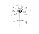
特に、挿通孔の円周方向幅をケーシングに対するステータコアの円周方向取付角度の最大振れ角度量と、ロータに対するレゾルバロータの円周方向取付角度の最大振れ角度量と、保持部材に対するレゾルバステータの円周方向取付角度の最大振れ角度量の総和した角度以上のケーシングと保持部材の円周方向相対回転を許容する長さに設定しているから、ケーシングに対する保持部材の取付位置の調節で確実にロータの回転位置を正確に検知できるようにすることができる。
また、ケーシングに対する保持部材の取付位置の調節で確実にロータの回転位置を正確に検知できるようにしつつ第二フランジ自体の円周方向幅を最小設定することができ、重量を必要最小限に留めることが可能となる。
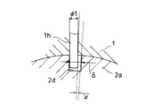
さらに、温度上昇によって圧入部位の緊迫力が低下してもピンと溝との係合によってステータコアのケーシングに対する円周方向の回り止めとして機能し、モータは温度上昇時にあっても問題なく大トルクを発生することが可能である。
そして、このように、ピンとステータコアの溝によってステータコアとケーシングとの回り止めが施されているので、温度上昇時の圧入部の緊迫力を従来モータ構造のそれよりも小さく設定しておく事ができ、圧入部の緊迫力によってステータコアに歪が生じてしまうような事態が防止されて、コギングトルクの発生やトルクリップルが大きくなるといった好ましくない事態を招来する事もない。
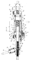
1a ケーシング本体
1b フランジ部
1c 第一フランジ
1d 小孔
1e コネクタ孔
1f 圧入部
1g 段部
1h ピン
1i 肉厚部
2 ステータ
2a ステータコア
2b 巻線
2c ティース
2d 溝
3 ロータ
3a ロータにおける拡径部
4 ギアケース
4a ギアケースにおける拡径部
4b ギアケースにおける第二フランジ
4c ハウジング
5 ガイド筒
5a ガイド筒における鍔
5b ガイド筒におけるフランジ部
6 バスバー
7 コネクタ
7a 嵌合部
7b 閉塞部
8,9 ボールベアリング
10 出力軸
11 ボール螺子ナット
10a 螺子溝
10b ラック
12 ピニオンギア
13 スタブシャフト
14 トルクセンサ
15 レゾルバロータ
16,21 ボルト
17 レゾルバステータ
17a フランジ
17b 孔
18 電線
19 レゾルバコネクタ
20 磁石
25 螺子
b ケーシング本体におけるステータが固定される軸方向範囲の一端の所定範囲
c 分割コア
L ケーシング本体のステータが固定される軸方向範囲
M モータ
n 螺子孔
p 挿通孔
PS パワーステアリング装置
w 挿通孔の円周方向幅
α ケーシングに対するステータコアの円周方向取付角度の最大振れ角度量
β ロータに対するレゾルバロータの円周方向取付角度の最大振れ角度量
γ 保持部材に対するレゾルバステータの円周方向取付角度の最大振れ角度量
Claims (2)
- 筒状のケーシングと、上記ケーシング内に固定される筒状のステータコアと、上記ケーシング内に回転自在に収容されてレゾルバロータが装着されるロータと、レゾルバステータを保持する保持部材とを備え、上記ケーシングと上記保持部材とを連結してなるモータ構造において、上記ケーシングの外周に複数の第一フランジを設け、上記各第一フランジに対応して上記保持部材の外周に複数の第二フランジを設け、対となる上記第一フランジあるいは上記第二フランジの一方にボルトを捻じ込む螺子孔を設けるとともに他方に上記ボルトの挿通が可能で当該ボルトの直径より円周方向幅が大きい挿通孔を設け、上記第一フランジと対応する上記第二フランジとを対面させながら上記ボルトによって締結することにより上記ケーシングと上記保持部材とを連結させ、上記ステータコアの外周に軸方向に沿う溝を形成して上記ケーシングに外部から内方に向けて突出させたピンを挿入させ、さらに上記挿通孔の円周方向幅を、上記ケーシングに対する上記ステータコアの円周方向取付角度の最大振れ角度量と、上記ロータに対する上記レゾルバロータの円周方向取付角度の最大振れ角度量と、上記保持部材に対する上記レゾルバステータの円周方向取付角度の最大振れ角度量の総和した角度以上の上記ケーシングと上記保持部材の円周方向相対回転を許容する長さに設定させ、また上記溝の溝幅より上記ピンの直径幅を小さく設定して上記ステータコアとケーシングとの最大振れ角度量を上記溝の幅と上記ピンの幅の寸法差で決していることを特徴とするモータ構造。
- ボール螺子ナットを保持する筒状のロータの一端側をケーシングで回転自在に支持するとともに他端側を保持部材で回転自在に支持し、上記ボール螺子ナット内に螺合するとともにピニオンギアに歯合するラックが形成されて両端が車両の車輪に連結される出力軸をケーシングおよび保持部材内に挿通し、保持部材内にピニオンギアを回転自在に収容してなる請求項1に記載のモータ構造。
Priority Applications (1)
| Application Number | Priority Date | Filing Date | Title |
|---|---|---|---|
| JP2007003287A JP4883696B2 (ja) | 2007-01-11 | 2007-01-11 | モータ構造 |
Applications Claiming Priority (1)
| Application Number | Priority Date | Filing Date | Title |
|---|---|---|---|
| JP2007003287A JP4883696B2 (ja) | 2007-01-11 | 2007-01-11 | モータ構造 |
Publications (2)
| Publication Number | Publication Date |
|---|---|
| JP2008172915A JP2008172915A (ja) | 2008-07-24 |
| JP4883696B2 true JP4883696B2 (ja) | 2012-02-22 |
Family
ID=39700463
Family Applications (1)
| Application Number | Title | Priority Date | Filing Date |
|---|---|---|---|
| JP2007003287A Expired - Fee Related JP4883696B2 (ja) | 2007-01-11 | 2007-01-11 | モータ構造 |
Country Status (1)
| Country | Link |
|---|---|
| JP (1) | JP4883696B2 (ja) |
Family Cites Families (8)
| Publication number | Priority date | Publication date | Assignee | Title |
|---|---|---|---|---|
| JPS6046378B2 (ja) * | 1980-06-13 | 1985-10-15 | オムロン株式会社 | 路面の凍結検知方法 |
| JP4101552B2 (ja) * | 2002-04-30 | 2008-06-18 | 本田技研工業株式会社 | 電動パワーステアリング装置 |
| JP4583983B2 (ja) * | 2005-03-17 | 2010-11-17 | 本田技研工業株式会社 | 回転センサ取付調整方法 |
| JP4894331B2 (ja) * | 2005-04-11 | 2012-03-14 | 日本電産株式会社 | ブラシレスモータ |
| JP2006329354A (ja) * | 2005-05-27 | 2006-12-07 | Jtekt Corp | ボールねじ装置およびそれを備えた電動パワーステアリング装置 |
| JP2007006570A (ja) * | 2005-06-22 | 2007-01-11 | Mitsuba Corp | ブラシレスモータ及びブラシレスモータのセンサ位置調整方法 |
| JP4685519B2 (ja) * | 2005-06-22 | 2011-05-18 | 株式会社ミツバ | 電動パワーステアリング装置及び電動パワーステアリング装置のセンサ位置調整方法 |
| JP5027497B2 (ja) * | 2006-12-25 | 2012-09-19 | カヤバ工業株式会社 | モータ構造 |
-
2007
- 2007-01-11 JP JP2007003287A patent/JP4883696B2/ja not_active Expired - Fee Related
Also Published As
| Publication number | Publication date |
|---|---|
| JP2008172915A (ja) | 2008-07-24 |
Similar Documents
| Publication | Publication Date | Title |
|---|---|---|
| US9452777B2 (en) | Power-steering device | |
| JP4367204B2 (ja) | 同期式ブラシレスモータ装置 | |
| US8739919B2 (en) | Motor and electric power steering system | |
| JP4512128B2 (ja) | モータの回転角検出装置 | |
| US7837002B2 (en) | Electric power steering apparatus | |
| JP2005138670A (ja) | 電動パワーステアリング装置および電動モータの組立方法 | |
| US8169111B2 (en) | Brushless motor | |
| JP2014187760A (ja) | モータ装置 | |
| JP2003324867A (ja) | ブラシレスモータ及びブラシレスモータを搭載した電動パワーステアリング装置 | |
| JP5141681B2 (ja) | モータ、動力装置及び電動パワーステアリング装置 | |
| JP5272707B2 (ja) | 電動モータおよび該電動モータを備えた電動パワーステアリング装置 | |
| JP2009141992A (ja) | 回転機 | |
| JP2013150385A (ja) | 電動モータ及びその製造方法 | |
| JP2011067056A (ja) | ブラシレスモータ | |
| US7893580B2 (en) | Positioning mechanism of resolver and electrically-driven power steering apparatus | |
| JP2018047726A (ja) | ステアリング装置 | |
| JP4685519B2 (ja) | 電動パワーステアリング装置及び電動パワーステアリング装置のセンサ位置調整方法 | |
| JP5059021B2 (ja) | ブラシレスモータ | |
| JP2008172915A (ja) | モータ構造 | |
| JP5801170B2 (ja) | ウォームギヤ装置の製造方法 | |
| JP5027497B2 (ja) | モータ構造 | |
| US11747230B2 (en) | Sensor device | |
| JP2008182776A (ja) | モータ構造 | |
| JP5064401B2 (ja) | ブラシレスモータ | |
| JP2023183045A (ja) | 操舵装置のトルク検出装置 |
Legal Events
| Date | Code | Title | Description |
|---|---|---|---|
| A621 | Written request for application examination |
Free format text: JAPANESE INTERMEDIATE CODE: A621 Effective date: 20090730 |
|
| A521 | Request for written amendment filed |
Free format text: JAPANESE INTERMEDIATE CODE: A523 Effective date: 20100330 |
|
| A977 | Report on retrieval |
Free format text: JAPANESE INTERMEDIATE CODE: A971007 Effective date: 20110825 |
|
| A131 | Notification of reasons for refusal |
Free format text: JAPANESE INTERMEDIATE CODE: A131 Effective date: 20110906 |
|
| A521 | Request for written amendment filed |
Free format text: JAPANESE INTERMEDIATE CODE: A523 Effective date: 20111031 |
|
| TRDD | Decision of grant or rejection written | ||
| A01 | Written decision to grant a patent or to grant a registration (utility model) |
Free format text: JAPANESE INTERMEDIATE CODE: A01 Effective date: 20111129 |
|
| A01 | Written decision to grant a patent or to grant a registration (utility model) |
Free format text: JAPANESE INTERMEDIATE CODE: A01 |
|
| A61 | First payment of annual fees (during grant procedure) |
Free format text: JAPANESE INTERMEDIATE CODE: A61 Effective date: 20111202 |
|
| FPAY | Renewal fee payment (event date is renewal date of database) |
Free format text: PAYMENT UNTIL: 20141216 Year of fee payment: 3 |
|
| R151 | Written notification of patent or utility model registration |
Ref document number: 4883696 Country of ref document: JP Free format text: JAPANESE INTERMEDIATE CODE: R151 |
|
| FPAY | Renewal fee payment (event date is renewal date of database) |
Free format text: PAYMENT UNTIL: 20141216 Year of fee payment: 3 |
|
| S533 | Written request for registration of change of name |
Free format text: JAPANESE INTERMEDIATE CODE: R313533 |
|
| R350 | Written notification of registration of transfer |
Free format text: JAPANESE INTERMEDIATE CODE: R350 |
|
| R250 | Receipt of annual fees |
Free format text: JAPANESE INTERMEDIATE CODE: R250 |
|
| LAPS | Cancellation because of no payment of annual fees |