JP4886624B2 - 永久磁石式回転電機、及び永久磁石式回転電機システム - Google Patents
永久磁石式回転電機、及び永久磁石式回転電機システム Download PDFInfo
- Publication number
- JP4886624B2 JP4886624B2 JP2007182002A JP2007182002A JP4886624B2 JP 4886624 B2 JP4886624 B2 JP 4886624B2 JP 2007182002 A JP2007182002 A JP 2007182002A JP 2007182002 A JP2007182002 A JP 2007182002A JP 4886624 B2 JP4886624 B2 JP 4886624B2
- Authority
- JP
- Japan
- Prior art keywords
- permanent magnet
- rotating electrical
- rotor
- electrical machine
- bridge
- Prior art date
- Legal status (The legal status is an assumption and is not a legal conclusion. Google has not performed a legal analysis and makes no representation as to the accuracy of the status listed.)
- Expired - Fee Related
Links
Images




Classifications
-
- H—ELECTRICITY
- H02—GENERATION; CONVERSION OR DISTRIBUTION OF ELECTRIC POWER
- H02K—DYNAMO-ELECTRIC MACHINES
- H02K1/00—Details of the magnetic circuit
- H02K1/06—Details of the magnetic circuit characterised by the shape, form or construction
- H02K1/22—Rotating parts of the magnetic circuit
- H02K1/27—Rotor cores with permanent magnets
-
- H—ELECTRICITY
- H02—GENERATION; CONVERSION OR DISTRIBUTION OF ELECTRIC POWER
- H02K—DYNAMO-ELECTRIC MACHINES
- H02K1/00—Details of the magnetic circuit
- H02K1/06—Details of the magnetic circuit characterised by the shape, form or construction
- H02K1/22—Rotating parts of the magnetic circuit
- H02K1/27—Rotor cores with permanent magnets
- H02K1/2706—Inner rotors
- H02K1/272—Inner rotors the magnetisation axis of the magnets being perpendicular to the rotor axis
- H02K1/274—Inner rotors the magnetisation axis of the magnets being perpendicular to the rotor axis the rotor consisting of two or more circumferentially positioned magnets
- H02K1/2753—Inner rotors the magnetisation axis of the magnets being perpendicular to the rotor axis the rotor consisting of two or more circumferentially positioned magnets the rotor consisting of magnets or groups of magnets arranged with alternating polarity
- H02K1/276—Magnets embedded in the magnetic core, e.g. interior permanent magnets [IPM]
-
- H—ELECTRICITY
- H02—GENERATION; CONVERSION OR DISTRIBUTION OF ELECTRIC POWER
- H02K—DYNAMO-ELECTRIC MACHINES
- H02K1/00—Details of the magnetic circuit
- H02K1/06—Details of the magnetic circuit characterised by the shape, form or construction
- H02K1/22—Rotating parts of the magnetic circuit
Landscapes
- Engineering & Computer Science (AREA)
- Power Engineering (AREA)
- Permanent Field Magnets Of Synchronous Machinery (AREA)
- Iron Core Of Rotating Electric Machines (AREA)
Description
このような中、回転電機の電気特性を改善するために、様々な形式の永久磁石式の回転子構造が検討されている。特許文献1の永久磁石式回転電機の回転子は、永久磁石を分割して配置し、この分割された永久磁石の背後にフラックスバリアを配置することで、回転子内部への漏洩磁束を低減して固定子のコイルとの鎖交磁束数を増加させている。
以下本発明の詳細を図面を用いながら説明する。各図において同一部分は同じ番号を付与している。
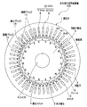
図1は、第1実施形態の永久磁石式回転電機の端部断面図である。永久磁石式回転電機100は、10極45スロットの回転電機であり、数百kW級の電車用に使用され、5000〜7000rpmの回転速度を許容する。
図3に応力規格化値及びモータ特性規格化値とT1/TMとの関係を示す。横軸は、鉄心ブリッジ16の厚さと永久磁石3の厚さとの比T1/TMであるが、鉄心ブリッジ16を厚くするほど、応力特性が高まり、モータ特性が低下する傾向がある。
図4は、本発明の第2実施形態の永久磁石式回転電機の端部断面図である。
永久磁石式回転電機110が、第1実施形態の永久磁石回転電機100と異なる点は、異極性の永久磁石3のそれぞれの磁極間にはフラックスバリア7が軸方向に凹設されている点である。このフラックスバリア7は、永久磁石3から発生する磁束が隣接する異極の永久磁石に流れることを防ぎ、磁束が固定子1の磁極に流れるようにしている。
第1実施形態、及び第2実施形態で示した回転子構造は、永久磁石3a(図2)を2分割し、磁極ブリッジ15を1本にしたが、図7,図8に示すように、永久磁石3aを3分割、あるいは4分割し、磁極ブリッジ15を2本、あるいは3本とすることもできる。これにより、鉄心ブリッジ16(図1)の変形をさらに低減することができる。
図9は、本実施形態の回転電機100,110を電車用の永久磁石回転電機システムに適用した例を示す。電車200は、第1実施形態及び第2実施形態で示した回転電機100,110と、増速ギア(変速ギア)60と、車輪50とを備え、回転電機100,110が増速ギア60を介して車輪50を駆動する。
また、図10の電車210のように、回転電機100,110の軸方向両側に車輪50を直接接続してもよい。また、ファン、ポンプなどの送風用の永久磁石回転電機システムの動力源としても十分適用が可能である。
本発明は前記した実施形態に限定されるものではなく、例えば、以下のような種々の変形が可能である。
(1)前記各実施形態は、永久磁石3の回転子内周側を平面としたが、他の形状でもよい。
(2)前記各実施形態は、鉄心ブリッジ16で極間ブリッジ14あるいは磁極ブリッジ15の間を接続していたが、磁極近傍では、鉄心ブリッジ16で接続する必要がない。このようにすれば、永久磁石3と固定子1との間隔が短くなるので磁気特性が向上する。特に、永久磁石3aを奇数個に分割した場合には、中心の永久磁石が固定子1の磁極に近接することになるので、有効である。なお、この場合でも。中心の永久磁石を挿設すること、すなわち、鉄心ブリッジ16の一部で永久磁石3b(図7)を押さえることは必要である。
2 回転子
3,3a 永久磁石
4 磁石スロット
5 回転子鉄心
6 シャフト
7 フラックスバリア
8 上コイル
9 底コイル
10 コイル
12 ティース
13 スロット
14 極間ブリッジ
15 磁極ブリッジ
16 鉄心ブリッジ
50 車輪
51,52,61,62 線
60 増速ギア
100,110 回転電機
200,210 電車
Claims (5)
- 固定子と回転子鉄心の外周部に複数の永久磁石を挿設した回転子とを備える永久磁石式回転電機において、
前記永久磁石は、周方向に複数に分割され、前記回転子の外周面側に傾斜面を有し、内周面側に平面を有した凸形状の断面を備えると共に、最薄部が異極の永久磁石に隣接したものであり、
前記分割された同極の永久磁石は、前記傾斜面を形成する第1の単一直線と前記平面を形成する第2の単一直線とこれらの単一直線に連続する4つの円弧と2本の他の直線とからなる断面形状を備え、
前記第1の単一直線の両端の外周側円弧の半径は、前記第2の単一直線の両端の内周側円弧の半径よりも大きな値であり、
前記回転子鉄心は、前記回転子外周側で、前記最薄部に対応する隣接する2つの円弧面と前記回転子の外周面とで形成される極間ブリッジを備え、
前記回転子鉄心は、前記永久磁石よりも外周側において、前記極間ブリッジの間に鉄心ブリッジが形成され、
前記永久磁石の最厚部の厚さをTMとし、前記鉄心ブリッジの厚さをT1としたとき、T1/TMの比が0.13≦T1/TM≦0.23の関係を満足するように配置し、
前記回転子鉄心は、前記回転子鉄心の外周円筒面から、前記隣接する2つの円弧面同士の中央部まで、フラックスバリアを凹設した
ことを特徴とする永久磁石式回転電機。 - 前記固定子は、継鉄部内周面に突出した複数のティースが形成され、このティースに集中巻あるいは分布巻によりコイルが巻回されたことを特徴とする請求項1に記載の永久磁石式回転電機。
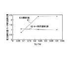
- 前記フラックスバリアと前記永久磁石との間の最短幅をT2とし、前記永久磁石の最厚高さをTMとしたとき、T2/TMの比が0.1≦T2/TM≦0.4の関係を満足するように配置したことを特徴とする請求項1に記載の永久磁石式回転電機。
- 請求項1に記載の永久磁石式回転電機を動力源としたことを特徴とする電車用の永久磁石式回転電機システム。
- 請求項1に記載の永久磁石式回転電機を駆動源としたことを特徴とする送風用の永久磁石式回転電機システム。
Priority Applications (5)
| Application Number | Priority Date | Filing Date | Title |
|---|---|---|---|
| JP2007182002A JP4886624B2 (ja) | 2007-07-11 | 2007-07-11 | 永久磁石式回転電機、及び永久磁石式回転電機システム |
| KR1020080066949A KR100989378B1 (ko) | 2007-07-11 | 2008-07-10 | 영구자석식 회전전기 및 영구자석식 회전전기장치 |
| EP08012529A EP2015425B1 (en) | 2007-07-11 | 2008-07-10 | Permanent magnet rotating electrical machine and permanent magnet rotating electrical machine system |
| US12/170,592 US8148865B2 (en) | 2007-07-11 | 2008-07-10 | Permanent magnet rotating electrical machine and permanent magnet rotating electrical machine system |
| CN2008101357576A CN101345444B (zh) | 2007-07-11 | 2008-07-11 | 永磁式旋转电机及永磁式旋转电机系统 |
Applications Claiming Priority (1)
| Application Number | Priority Date | Filing Date | Title |
|---|---|---|---|
| JP2007182002A JP4886624B2 (ja) | 2007-07-11 | 2007-07-11 | 永久磁石式回転電機、及び永久磁石式回転電機システム |
Publications (2)
| Publication Number | Publication Date |
|---|---|
| JP2009022089A JP2009022089A (ja) | 2009-01-29 |
| JP4886624B2 true JP4886624B2 (ja) | 2012-02-29 |
Family
ID=39863059
Family Applications (1)
| Application Number | Title | Priority Date | Filing Date |
|---|---|---|---|
| JP2007182002A Expired - Fee Related JP4886624B2 (ja) | 2007-07-11 | 2007-07-11 | 永久磁石式回転電機、及び永久磁石式回転電機システム |
Country Status (5)
| Country | Link |
|---|---|
| US (1) | US8148865B2 (ja) |
| EP (1) | EP2015425B1 (ja) |
| JP (1) | JP4886624B2 (ja) |
| KR (1) | KR100989378B1 (ja) |
| CN (1) | CN101345444B (ja) |
Families Citing this family (22)
| Publication number | Priority date | Publication date | Assignee | Title |
|---|---|---|---|---|
| JP4975337B2 (ja) * | 2006-02-28 | 2012-07-11 | 本田技研工業株式会社 | モータを備える車両 |
| JP4627788B2 (ja) * | 2008-06-27 | 2011-02-09 | 株式会社日立製作所 | 永久磁石式回転電機 |
| JP2010166683A (ja) * | 2009-01-15 | 2010-07-29 | Fujitsu General Ltd | 永久磁石型モータ |
| JP5193094B2 (ja) * | 2009-03-03 | 2013-05-08 | 本田技研工業株式会社 | 永久磁石電動機 |
| JP2010246185A (ja) * | 2009-04-01 | 2010-10-28 | Honda Motor Co Ltd | ロータおよびモータ |
| WO2011001533A1 (ja) * | 2009-07-03 | 2011-01-06 | 三菱電機株式会社 | 永久磁石型回転電機 |
| JP5292271B2 (ja) | 2009-12-24 | 2013-09-18 | 株式会社日立製作所 | 永久磁石式回転電機 |
| EP2395630A1 (en) * | 2010-06-10 | 2011-12-14 | Siemens Aktiengesellschaft | A permanent magnet machine, in particular a generator for a wind turbine |
| CA2823656C (en) * | 2011-01-11 | 2018-10-02 | Qm Power, Inc. | Magnetically isolated phase interior permanent magnet electrical rotating machine |
| EP2721723B1 (de) * | 2011-06-17 | 2017-04-05 | Sew-Eurodrive GmbH & Co. KG | Synchronmotor |
| JP6095263B2 (ja) * | 2011-11-10 | 2017-03-15 | 信越化学工業株式会社 | 埋込磁石型モータおよび圧縮機 |
| DE112014000526B4 (de) * | 2013-01-23 | 2018-03-01 | Mitsubishi Electric Corporation | Rotor und drehende elektrische Maschine, die diesen Rotor enthält |
| JP6327803B2 (ja) * | 2013-07-09 | 2018-05-23 | 久慶 ▲ふく▼楊 | 大出力高効率単相多極発電機 |
| JP6377543B2 (ja) * | 2014-11-21 | 2018-08-22 | 株式会社神戸製鋼所 | 磁石埋込型回転電機 |
| DE102015212165A1 (de) * | 2015-06-30 | 2017-01-05 | Robert Bosch Gmbh | Elektrische Maschine mit reduziertem Nutrasten und Drehmomentwelligkeit |
| EP3386075B1 (en) * | 2017-04-06 | 2020-07-29 | LG Electronics Inc. | Electric motor with permament magnet and compressor having the same |
| JP6940222B2 (ja) * | 2018-01-25 | 2021-09-22 | 公益財団法人鉄道総合技術研究所 | 回転電機及び車両 |
| JP7226162B2 (ja) * | 2019-02-25 | 2023-02-21 | 株式会社デンソー | 回転電機 |
| CN113424398B (zh) * | 2019-03-27 | 2024-06-21 | 大金工业株式会社 | 电动机 |
| JP7378369B2 (ja) * | 2020-09-09 | 2023-11-13 | 日立Astemo株式会社 | 回転電機の回転子、回転電機及び電動駆動装置 |
| JP2022130851A (ja) * | 2021-02-26 | 2022-09-07 | 三菱重工業株式会社 | 回転子及びこれを備えた外周駆動ファン |
| CN223206907U (zh) * | 2024-08-29 | 2025-08-08 | 华为技术有限公司 | 电机转子、电机、动力总成及电动车 |
Family Cites Families (16)
| Publication number | Priority date | Publication date | Assignee | Title |
|---|---|---|---|---|
| JPH09285088A (ja) * | 1996-04-12 | 1997-10-31 | Hitachi Ltd | 永久磁石回転電機及びそれを用いた電動車両 |
| JP3509508B2 (ja) * | 1997-02-21 | 2004-03-22 | アイシン・エィ・ダブリュ株式会社 | 永久磁石式同期モータ |
| JPH11355986A (ja) * | 1998-06-09 | 1999-12-24 | Denso Corp | 回転電機の磁石埋設ロータ |
| JP2000350393A (ja) | 1999-03-29 | 2000-12-15 | Shin Etsu Chem Co Ltd | 永久磁石モータ |
| JP4854867B2 (ja) * | 2001-05-10 | 2012-01-18 | 三菱電機株式会社 | 電動機 |
| JP3835231B2 (ja) | 2001-10-04 | 2006-10-18 | 松下電器産業株式会社 | 電動機 |
| JP2003164082A (ja) * | 2001-11-22 | 2003-06-06 | Hitachi Metals Ltd | フェライト磁石および回転機、フェライト磁石の製造方法 |
| JP4113353B2 (ja) * | 2001-11-29 | 2008-07-09 | 澤藤電機株式会社 | 回転電機 |
| EP1450470B1 (en) * | 2003-02-21 | 2012-09-19 | Rexroth Indramat GmbH | Interior permanent magnet synchronous machine |
| JP2005045986A (ja) * | 2003-07-25 | 2005-02-17 | Denso Corp | 永久磁石回転電機 |
| JP4791013B2 (ja) * | 2004-07-22 | 2011-10-12 | 三菱電機株式会社 | ブラシレスモータ |
| JP4574297B2 (ja) * | 2004-09-13 | 2010-11-04 | 日産自動車株式会社 | 回転電機のロータ |
| JP5244290B2 (ja) * | 2005-08-23 | 2013-07-24 | 日産自動車株式会社 | 回転電機の回転子構造 |
| JP2007097387A (ja) * | 2005-08-31 | 2007-04-12 | Toshiba Corp | 回転電機 |
| JP2007068357A (ja) * | 2005-09-01 | 2007-03-15 | Toshiba Industrial Products Manufacturing Corp | 回転電機の回転子及びそれを用いた回転電機 |
| JP4848169B2 (ja) * | 2005-10-20 | 2011-12-28 | 三菱重工業株式会社 | Ipmモータ |
-
2007
- 2007-07-11 JP JP2007182002A patent/JP4886624B2/ja not_active Expired - Fee Related
-
2008
- 2008-07-10 EP EP08012529A patent/EP2015425B1/en not_active Ceased
- 2008-07-10 KR KR1020080066949A patent/KR100989378B1/ko not_active Expired - Fee Related
- 2008-07-10 US US12/170,592 patent/US8148865B2/en not_active Expired - Fee Related
- 2008-07-11 CN CN2008101357576A patent/CN101345444B/zh not_active Expired - Fee Related
Also Published As
| Publication number | Publication date |
|---|---|
| EP2015425B1 (en) | 2011-09-21 |
| US20090015090A1 (en) | 2009-01-15 |
| EP2015425A2 (en) | 2009-01-14 |
| US8148865B2 (en) | 2012-04-03 |
| CN101345444B (zh) | 2011-06-15 |
| CN101345444A (zh) | 2009-01-14 |
| KR20090006766A (ko) | 2009-01-15 |
| EP2015425A3 (en) | 2009-12-02 |
| JP2009022089A (ja) | 2009-01-29 |
| KR100989378B1 (ko) | 2010-10-25 |
Similar Documents
| Publication | Publication Date | Title |
|---|---|---|
| JP2009022089A (ja) | 永久磁石式回転電機、及び永久磁石式回転電機システム | |
| US7408281B2 (en) | Stator and brushless motor | |
| JP5288724B2 (ja) | 回転電機の回転子及び回転電機 | |
| JP5159153B2 (ja) | 回転電機の回転子及び回転電機 | |
| KR101730525B1 (ko) | 브러시없는 동기식 모터 | |
| JP4627788B2 (ja) | 永久磁石式回転電機 | |
| US10862355B2 (en) | Armature with a core having teeth of different circumferential widths and electric motor including the armature and a rotor | |
| US8217544B2 (en) | Motor-generator having stator and inner and outer rotors | |
| JP5308832B2 (ja) | 永久磁石式回転電機 | |
| JP2005176424A (ja) | 回転電機の回転子 | |
| WO2011001533A1 (ja) | 永久磁石型回転電機 | |
| JP2013070595A (ja) | 3相回転電機及びその製造方法 | |
| JP6567304B2 (ja) | 回転電機及び巻上機 | |
| JP5248048B2 (ja) | 回転電機の回転子及び回転電機 | |
| CN117397149A (zh) | 旋转电机的转子和包括这样的转子的旋转电机 | |
| JP5567775B2 (ja) | ロータおよび回転電機 | |
| US20130057106A1 (en) | Manufacturing method of rotating electric machine and rotating electric machine | |
| JP6132156B2 (ja) | 回転電機 | |
| JP2009077525A (ja) | 回転電機の回転子及び回転電機 | |
| CN101253668A (zh) | 包含带有倾斜齿的扁平定子的电机 | |
| JP7412362B2 (ja) | トルクリップルを低減するロータ形態を伴う回転電気機械 | |
| JP5854268B2 (ja) | 回転電機の固定子 | |
| JP2010154648A (ja) | モータ | |
| JP7455994B2 (ja) | 回転電機 | |
| JP6498775B2 (ja) | 固定子および回転電機 |
Legal Events
| Date | Code | Title | Description |
|---|---|---|---|
| A621 | Written request for application examination |
Free format text: JAPANESE INTERMEDIATE CODE: A621 Effective date: 20090318 |
|
| A977 | Report on retrieval |
Free format text: JAPANESE INTERMEDIATE CODE: A971007 Effective date: 20090728 |
|
| A131 | Notification of reasons for refusal |
Free format text: JAPANESE INTERMEDIATE CODE: A131 Effective date: 20090804 |
|
| A521 | Request for written amendment filed |
Free format text: JAPANESE INTERMEDIATE CODE: A523 Effective date: 20091005 |
|
| A131 | Notification of reasons for refusal |
Free format text: JAPANESE INTERMEDIATE CODE: A131 Effective date: 20100316 |
|
| A521 | Request for written amendment filed |
Free format text: JAPANESE INTERMEDIATE CODE: A523 Effective date: 20100514 |
|
| A02 | Decision of refusal |
Free format text: JAPANESE INTERMEDIATE CODE: A02 Effective date: 20110111 |
|
| A521 | Request for written amendment filed |
Free format text: JAPANESE INTERMEDIATE CODE: A523 Effective date: 20110706 |
|
| A521 | Request for written amendment filed |
Free format text: JAPANESE INTERMEDIATE CODE: A821 Effective date: 20110708 |
|
| A911 | Transfer to examiner for re-examination before appeal (zenchi) |
Free format text: JAPANESE INTERMEDIATE CODE: A911 Effective date: 20110729 |
|
| A131 | Notification of reasons for refusal |
Free format text: JAPANESE INTERMEDIATE CODE: A131 Effective date: 20111011 |
|
| A521 | Request for written amendment filed |
Free format text: JAPANESE INTERMEDIATE CODE: A523 Effective date: 20111115 |
|
| TRDD | Decision of grant or rejection written | ||
| A01 | Written decision to grant a patent or to grant a registration (utility model) |
Free format text: JAPANESE INTERMEDIATE CODE: A01 Effective date: 20111206 |
|
| A01 | Written decision to grant a patent or to grant a registration (utility model) |
Free format text: JAPANESE INTERMEDIATE CODE: A01 |
|
| A61 | First payment of annual fees (during grant procedure) |
Free format text: JAPANESE INTERMEDIATE CODE: A61 Effective date: 20111209 |
|
| FPAY | Renewal fee payment (event date is renewal date of database) |
Free format text: PAYMENT UNTIL: 20141216 Year of fee payment: 3 |
|
| R150 | Certificate of patent or registration of utility model |
Ref document number: 4886624 Country of ref document: JP Free format text: JAPANESE INTERMEDIATE CODE: R150 Free format text: JAPANESE INTERMEDIATE CODE: R150 |
|
| LAPS | Cancellation because of no payment of annual fees |