JP4894366B2 - Blur correction device and optical apparatus - Google Patents
Blur correction device and optical apparatus Download PDFInfo
- Publication number
- JP4894366B2 JP4894366B2 JP2006165024A JP2006165024A JP4894366B2 JP 4894366 B2 JP4894366 B2 JP 4894366B2 JP 2006165024 A JP2006165024 A JP 2006165024A JP 2006165024 A JP2006165024 A JP 2006165024A JP 4894366 B2 JP4894366 B2 JP 4894366B2
- Authority
- JP
- Japan
- Prior art keywords
- liquid
- blur correction
- layer
- correction device
- lens
- Prior art date
- Legal status (The legal status is an assumption and is not a legal conclusion. Google has not performed a legal analysis and makes no representation as to the accuracy of the status listed.)
- Expired - Fee Related
Links
Images



Landscapes
- Automatic Focus Adjustment (AREA)
- Adjustment Of Camera Lenses (AREA)
- Surface Treatment Of Optical Elements (AREA)
Description
本発明は、ブレ補正装置と、このブレ補正装置を用いた光学機器とに関する。 The present invention relates to a shake correction apparatus and an optical apparatus using the shake correction apparatus .
従来から、屈折率の異なる二種類の液体を容器内に充填して液体レンズを構成するとともに、電圧の印加で液体の界面形状を変化させることで可変焦点レンズとして用いる光学系が提案されている。なお、上記の光学系の一例が特許文献1に開示されている。
しかし、従来の液体レンズでは、第1の液体の屈折率と第2の液体の屈折率との差を大きくして液体レンズ全体の屈折率を上げようとすると、第1の液体と第2の液体との界面において入射光束に対する反射率が大きくなる点で改善の余地があった。
本発明は、第1の液体と第2の液体との界面における反射率を小さくしたブレ補正装置を提供することを目的とする。
However, in the conventional liquid lens, if the refractive index of the entire liquid lens is increased by increasing the difference between the refractive index of the first liquid and the refractive index of the second liquid, the first liquid and the second liquid There is room for improvement in that the reflectance with respect to the incident light beam becomes large at the interface with the liquid.
An object of the present invention is to provide a shake correction apparatus in which the reflectance at the interface between the first liquid and the second liquid is reduced.
第1の発明のブレ補正装置は、導電性を有する第1液体と、第2液体と、第1層と、容器と、複数の第1電極と、複数の第2電極と、ブレ補正制御部とを備える。第2液体は、第1液体とは異なる屈折率を有し、誘電性を有する。第1層は、第1液体と接触する第1面が第1液体と親和性を有し、第2液体と接触する第2面が第2液体と親和性を有し、第1液体の屈折率と第2液体の屈折率との間の屈折率を有する。容器は、第1液体、第2液体及び第1層を収容する。複数の第1電極は、絶縁層を介して第1液体に対向するように容器の内部に備えられる。複数の第2電極は、入射光の光軸方向に沿って第1電極と平行に備えられ、第2液体に対向するように容器の内部に備えられる。ブレ補正制御部は、装置のブレ量に対応するブレ検出信号に応じて第1電極および第2電極に印加する電圧を制御することにより、第1液体と第2液体との界面形状を変化させて像ブレを補正する。
第2の発明は、第1の発明において、第1層は、第1液体および第2液体から分離して備えられている。
Blur correction apparatus of the first invention comprises a first liquid having conductivity, and the second liquid body, a first layer, a container, a plurality of first electrodes, a plurality of second electrodes, the blur correction control A part. Second liquid body has a refractive index different from that of the first liquid member having a dielectric. The first layer, the first surface in contact with the first liquid has an affinity with the first liquid, a second surface in contact with the second liquid has an affinity with the second liquid, the first liquid member to have a refractive index between the refractive index and the refractive index of the second liquid member. The container contains the first liquid, the second liquid, and the first layer. The plurality of first electrodes are provided inside the container so as to face the first liquid through the insulating layer. The plurality of second electrodes are provided in parallel with the first electrode along the optical axis direction of the incident light, and are provided inside the container so as to face the second liquid. The shake correction control unit changes the interface shape between the first liquid and the second liquid by controlling the voltage applied to the first electrode and the second electrode in accordance with the shake detection signal corresponding to the shake amount of the apparatus. Correct the image blur.
The second invention according to the first invention, the first layer is provided separately from the first liquid member and the second fluid member.
第3の発明は、第1または第2の発明において、第1層が流動性を有する。
第4の発明は、第1から第3のいずれかの発明において、第1層は、粘性体、液体、高分子膜および高分子粒のいずれか1つを含む。
第5の発明は、第1から第4のいずれかの発明において、第1液体、第2液体および第1層は、入射光の光軸に沿って配置されている。
According to a third invention, in the first or second invention, the first layer has fluidity.
In a fourth invention according to any one of the first to third inventions, the first layer includes any one of a viscous material , a liquid, a polymer film, and a polymer particle.
A fifth invention, in the fourth one of the invention from the first, the first liquid member, the second liquid member and the first layer, is arranged along the optical axis of the incident light.
第6の発明は、第1から第5のいずれかの発明において、第1層は、入射光束に対する反射防止膜としての役割を有する。
第7の発明は、第1から第6のいずれかの発明において、入射光の波長をλとし、第1層の屈折率をnとしたとき、第1層の厚さはλ/(4n)である。
第8の発明の光学機器は、第1から第7のいずれかの発明のブレ補正装置を用いたことを特徴とする。
In a sixth aspect based on any one of the first to fifth aspects, the first layer has a role as an antireflection film for the incident light flux.
In a seventh invention according to any one of the first to sixth inventions, when the wavelength of incident light is λ and the refractive index of the first layer is n, the thickness of the first layer is λ / (4n) It is.
An optical apparatus according to an eighth aspect is characterized in that the blur correction apparatus according to any one of the first to seventh aspects is used.
本発明によれば、第1の液体と第2の液体との界面での反射率を小さくしたブレ補正装置を提供できる。
ADVANTAGE OF THE INVENTION According to this invention, the blurring correction apparatus which made small the reflectance in the interface of a 1st liquid and a 2nd liquid can be provided.
以下、添付の図面を用いて、本発明の一実施形態について説明する。
(液体レンズの説明)
図1から図3は、本実施形態の液体レンズの動作を示す説明図である。なお、図1は液体レンズの光軸方向と水平に切断した状態を示している。
図1に示す液体レンズ120は、導電性液体1と、誘電性液体2と、容器5と、絶縁層6と、上部電極7a,8aと、下部電極7b,8bと、第3物質層13とを有している。
Hereinafter, an embodiment of the present invention will be described with reference to the accompanying drawings.
(Description of liquid lens)
1 to 3 are explanatory views showing the operation of the liquid lens of the present embodiment. FIG. 1 shows a state in which the liquid lens is cut horizontally with the optical axis direction.
The liquid lens 120 shown in FIG. 1 includes a
容器5は、円筒状の内部空間を有する容器本体と、容器本体の開口を塞ぐ蓋体とで構成されている。この容器5の材質は、絶縁性を有する透光性樹脂などで構成されている。そして、液体レンズ120の組立状態では、容器5に液体レンズを構成する各部品が収納される。便宜上、図1では容器5を一体化した一部品として示す。なお、容器5の内側側面には撥水加工が施されている。 The container 5 includes a container body having a cylindrical inner space and a lid that closes the opening of the container body. The material of this container 5 is comprised with the translucent resin etc. which have insulation. In the assembled state of the liquid lens 120, each component constituting the liquid lens is stored in the container 5. For convenience, FIG. 1 shows the container 5 as an integral part. The inner side surface of the container 5 is water repellent.
容器5の内部には、いずれも透光性を有する導電性液体1および誘電性液体2が充填されている。導電性液体1および誘電性液体2の間には、透光性を有する第3物質層13が形成されている。第3物質層13は、導電性液体1および誘電性液体2から分離して容器5内に備えられている。すなわち、容器5内において導電性液体1および誘電性液体2は第3物質層13で隔てられており、各々の液体が混じり合うことはない。なお、第3物質層13は、入射光束に対する反射防止膜の役割も果たす。
The inside of the container 5 is filled with a
また、導電性液体1、誘電性液体2および第3物質層13は、液体レンズ120に対する入射光の光軸に沿って配置されている。具体的には、図1では液体レンズ120の光軸方向入射側(図1の上側)から順に、誘電性液体2、第3物質層13、導電性液体1がそれぞれ層をなすように配置されている。なお、容器5の内側側面の撥水加工によって、導電性液体1の図中上側の界面は、誘電性液体2および第3物質層13に対して中央部が張り出した凸球面をなしている。
Further, the
ここで、導電性液体1には例えば無機塩の水溶液が使用される。また、誘電性液体2には例えばフッ素系オイルが使用される。そして、導電性液体1および誘電性液体2は各々が異なる屈折率を有し、導電性液体1は誘電性液体2よりも屈折率が大きくなるように設定されている。
第3物質層13は流動性のある物質で構成されており、導電性液体1と誘電性液体2との界面形状の変形を許容する。例えば、第3物質層13は、粘性体、液体、高分子膜、高分子粒のいずれか1つを含んでいる。また、第3物質層13の屈折率は、導電性液体1の屈折率と誘電性液体2の屈折率との間の値となるように設定される。なお、第3物質層13の厚さは、入射光の波長をλとし、第3物質層13の屈折率をnとするときに、λ/(4n)の値に設定することが特に好ましい。
Here, for example, an aqueous solution of an inorganic salt is used for the
The third material layer 13 is made of a fluid material and allows deformation of the interface shape between the
また、図1において、第3物質層13の下面は導電性液体1との親和性を有している。同様に、第3物質層13の上面は誘電性液体2との親和性を有している。ここで、親和性とは、ある物質が他の物質と容易に結合する性質を意味する。もっとも、実際には、第3物質層13が導電性液体1および誘電性液体2の両方に親和性を有する必要はない。例えば、第3物質層13が導電性液体1または誘電性液体2の一方に対して親和性を有していれば足りる。
In FIG. 1, the lower surface of the third material layer 13 has affinity with the
図1において、上部電極7aおよび下部電極7bと、上部電極8aおよび下部電極8bとは、各々1対の電極を構成する。そして、上記の1対の電極間には直流電圧が印加される。また、下部電極7b,8bの容器内面側はそれぞれ絶縁層6で被覆されている。なお、図1はいずれの電極にも電圧が印加されていない状態を示している。
図2は、上部電極8aと下部電極8bとの間に直流電圧を印加したときの状態を示す図である。上部電極8aと下部電極8bとに直流電圧が印加されると、電界によって導電性液体1と誘電性液体2との表面張力が変化し、導電性液体1が電極8a,8bの方に引かれて変位した状態となる。これにより、導電性液体1と誘電性液体2との界面の形状が変化して、液体レンズ120の光学特性が変化する。
In FIG. 1, an
FIG. 2 is a diagram showing a state when a DC voltage is applied between the upper electrode 8a and the lower electrode 8b. When a DC voltage is applied to the upper electrode 8a and the lower electrode 8b, the surface tension between the
また、本実施形態の液体レンズ120では、レンズの円周方向に4対の電極を配置している。これにより、液体レンズ120における界面の変位を、光軸に対して垂直な面内の2方向に制御可能としている。図3は、液体レンズ120を光軸方向から見た図である。容器5の円周上には、円弧状の4対の電極7,8,9,10が配置されている。そして、電極7または電極8への電圧印加により、紙面左右方向(X方向)に液体レンズ120を制御できる。同様に、電極9または電極10への電圧印加により、紙面上下方向(Y方向)に液体レンズ120を制御できる。 In the liquid lens 120 of the present embodiment, four pairs of electrodes are arranged in the circumferential direction of the lens. Thereby, the displacement of the interface in the liquid lens 120 can be controlled in two directions in a plane perpendicular to the optical axis. FIG. 3 is a view of the liquid lens 120 as viewed from the optical axis direction. On the circumference of the container 5, four arc-shaped pairs of electrodes 7, 8, 9, 10 are arranged. Then, by applying a voltage to the electrode 7 or the electrode 8, the liquid lens 120 can be controlled in the left-right direction (X direction) on the paper surface. Similarly, by applying a voltage to the electrode 9 or the electrode 10, the liquid lens 120 can be controlled in the vertical direction (Y direction) on the paper surface.
ここで、図3に示す各電極(7〜10)は、各々が上部電極および下部電極を有している。電極9,10の構成は、図1および図2に示した電極7a,7b,8a,8bの構成とほぼ共通するので、個別の図示と重複説明は省略する。また、液体レンズ120の屈折率を高精度に制御する必要がある場合には、電極の分割数をさらに増やせばよい。なお、液体レンズ120を有効に駆動するためには、少なくとも3対の電極が必要となる。
Here, each of the electrodes (7 to 10) shown in FIG. 3 has an upper electrode and a lower electrode. The configuration of the electrodes 9 and 10 is almost the same as the configuration of the
以上の構成によれば、簡素な機構で光学特性を変化できるとともに、小型化が容易な液体レンズ120を提供できる。特に本実施形態では、第3物質層13によって入射光束の界面での反射が防止されるので、入射光束の利用効率を高めた高性能の液体レンズ120が実現できる。
なお、本実施形態では、容器5内に電極(7〜10)を設ける例を説明したが、導電性液体1に対して電圧を直接印加する構成としてもよい。
According to the above configuration, it is possible to provide the liquid lens 120 that can change the optical characteristics with a simple mechanism and can be easily reduced in size. In particular, in the present embodiment, the third material layer 13 prevents reflection at the interface of the incident light beam, so that a high-performance liquid lens 120 with improved utilization efficiency of the incident light beam can be realized.
In this embodiment, the example in which the electrodes (7 to 10) are provided in the container 5 has been described. However, a voltage may be directly applied to the
(本実施形態の具体例)
次に、本実施形態の具体例について説明する。ここで、導電性液体1の屈折率をnb、誘電性液体2の屈折率をna、第3物質層13の屈折率をnc、第3物質層の膜厚をdとする。なお、本実施形態での屈折率の値は、na<nc<nbの関係を有する。この場合、界面に対して垂直に入射する光の反射率Rcは、次式で表される。
(Specific example of this embodiment)
Next, a specific example of this embodiment will be described. Here, the refractive index of the
Rc=((na×nb−nc2)/(na×nb+nc2))2
第3物質層13の上面と下面との反射強度が等しいため、反射光が無い状態においては、Rc=0である。そのため、振幅条件は次式で表される。
nc=(na×nb)1/2
また、第3物質層13の上下二つの境界面での反射光の位相差をλ/2にする必要がある。そのため、位相条件は次式で表される。
Rc = ((na × nb−nc 2 ) / (na × nb + nc 2 )) 2
Since the reflection intensity of the upper surface and the lower surface of the third material layer 13 is equal, Rc = 0 in a state where there is no reflected light. Therefore, the amplitude condition is expressed by the following equation.
nc = (na × nb) 1/2
In addition, the phase difference of the reflected light at the upper and lower boundary surfaces of the third material layer 13 needs to be λ / 2. Therefore, the phase condition is expressed by the following equation.
nc×d=λ/4
したがって、上記の振幅条件と位相条件を満たせば、波長λに対して反射率Rcが0となる。一般に、液体レンズの界面での反射はある特定の波長λにおいて特に大きくなる。したがって、当該波長λについて、上記の振幅条件と位相条件とを満たすように液体レンズを設計すれば、液体レンズの界面に垂直に入射する光の反射率を大幅に低減できる。
nc × d = λ / 4
Therefore, if the above amplitude condition and phase condition are satisfied, the reflectance Rc becomes 0 with respect to the wavelength λ. In general, reflection at the interface of the liquid lens is particularly large at a specific wavelength λ. Therefore, if the liquid lens is designed so as to satisfy the amplitude condition and the phase condition for the wavelength λ, the reflectance of light incident perpendicularly to the interface of the liquid lens can be greatly reduced.
(比較例)
上記した具体例に対する比較例として、第3物質層13を設けていない液体レンズの界面における反射率Rの一例を示す。
導電性液体(屈折率大)の屈折率を1.8、誘電性液体(屈折率小)の屈折率を1.3とする。この場合、液体レンズの界面に垂直に入射する光の反射率Rは、次式で示すことができる。
(Comparative example)
As a comparative example to the specific example described above, an example of the reflectance R at the interface of the liquid lens not provided with the third material layer 13 is shown.
The refractive index of the conductive liquid (high refractive index) is 1.8, and the refractive index of the dielectric liquid (low refractive index) is 1.3. In this case, the reflectance R of light incident perpendicularly to the interface of the liquid lens can be expressed by the following equation.
R=((1.8−1.3)/(1.8+1.3))2
上記の式において、反射率Rはパーセントで表現すると約2.6%であり、上記具体例の反射率Rcよりも大きな値となってしまう。したがって、本実施形態によれば、液体レンズの界面における光の反射率を大幅に低減できることが分かる。
(液体レンズの光学機器への応用例1)
図4は、本実施形態の液体レンズ120をカメラシステムに適用した場合を示す模式図である。同図の例では、上述の液体レンズ120が、一眼レフ型のカメラシステムのレンズシフト系のブレ補正装置に適用されている。
R = ((1.8−1.3) / (1.8 + 1.3)) 2
In the above formula, the reflectance R is about 2.6% in terms of percentage, which is larger than the reflectance Rc of the specific example. Therefore, according to the present embodiment, it can be seen that the reflectance of light at the interface of the liquid lens can be greatly reduced.
(Application example 1 of liquid lens to optical equipment)
FIG. 4 is a schematic diagram showing a case where the liquid lens 120 of the present embodiment is applied to a camera system. In the example of the figure, the above-described liquid lens 120 is applied to a lens shift system blur correction device of a single-lens reflex camera system.
図4のカメラシステムは、交換レンズ200とカメラボディ210とを有している。そして、交換レンズ200内に上記のブレ補正装置が搭載されている。
交換レンズ200は、角速度センサ15と、増幅部20と、A/D変換部30と、基礎値演算部40と、減算器50と、目標駆動値演算部60と、駆動量データテーブル70と、撮影倍率情報計算部90と、撮影距離情報計算部100と、ブレ補正レンズ光学情報計算部110と、ROM115と、ドライバ80と、像ブレ補正用の液体レンズ120とを有している。
The camera system in FIG. 4 includes an interchangeable lens 200 and a camera body 210. The blur correction device is mounted in the interchangeable lens 200.
The interchangeable lens 200 includes an
また、基礎値演算部40、減算器50、目標駆動値演算部60、駆動量データテーブル70、撮影倍率情報計算部90、撮影距離情報計算部100、ブレ補正レンズ光学情報計算部110、ROM115は、図示するようにマイコン150によって構成されている。なお、ROM115は、マイコン150の制御方法(制御手順)を記憶している。
角速度センサ15は、カメラシステムに加えられた振動を角速度として検出して、検出された角速度に応じた角速度検出信号を出力する。角速度センサ15としては、通常、コリオリ力を検出する圧電振動式角速度センサが用いられる。
The
The
増幅部20は、角速度センサ15から出力される角速度検出信号を増幅する。角速度センサ10の出力は小さいため、A/D変換部30でデジタル化してマイコン内で処理しようとしても、角速度検出信号の分解能が低すぎる(すなわち、1ビットあたりの角速度検出信号が大きすぎる)。そのため、このままでは正確な振動検出を行うことができず、像ブレ補正の精度を上げることができない。そこで、増幅部20は、角速度検出信号をA/D変換部30に入力する前に増幅する。これにより、マイコン150内での角速度検出信号の分解能を上げる(1ビットあたりの角速度検出信号を小さくする)ことができ、ブレ補正精度を上げることが可能になる。また、増幅部20は、角速度検出信号を増幅するだけではなく、角速度センサ15の出力に含まれる高周波ノイズを低減させるため、ローパスフィルタ等を備えてもよい。増幅した角速度検出信号は、A/D変換部30へ送信される。
The amplifying
A/D変換部30は、増幅部20から送られてきたアナログの角速度信号をデジタル信号に変換する。角速度検出信号をデジタル信号に変換することで、マイコン150内での演算処理が可能となる。なお、このA/D変換部30は、図4に示すようにマイコン150と別に設けてもよいし、マイコン150にA/D変換部が内蔵されている場合には、そのA/D変換部を利用してもよい。なお、角速度検出信号は、A/D変換部30においてアナログ信号からデジタル信号に変換された後、基準値演算部40と減算器50とに入力される。
The A /
基準値演算部40は、角速度検出信号に基づいて、振れが存在しないときの角速度検出信号の基準値を演算する。すなわち、基準値演算部40は、振れがゼロのときの角速度検出信号を基準値として減算器50に出力する。
基準値演算部40における基準値の演算方法の一例として、次の(数1)に示す移動平均がある。
The reference
As an example of a reference value calculation method in the reference

この他、一般的なローパスフィルタを利用して基準値を算出してもよい。例えば、増幅部20とA/D変換部30との間にローパスフィルタを設けてもよい。
減算器50は、A/D変換部30から出力される角速度検出信号から前記基準値を減算して角速度で表される振れ検出信号を求め、求めた振れ検出信号を目標駆動値演算部60へ出力する。
In addition, the reference value may be calculated using a general low-pass filter. For example, a low pass filter may be provided between the
The
目標駆動値演算部60は、角速度で表される振れ検出信号を時間積分することにより振れ角度情報に変換する。その後、目標駆動値演算部60は、振れ角度情報と、撮影倍率情報計算部90で演算される撮影倍率情報βと、撮影距離情報計算部100で演算されるレンズの焦点距離情報Rと、ブレ補正レンズ光学情報計算部110で演算されるブレ補正レンズ光学情報(ブレ補正係数K)とを利用して、液体レンズ120を駆動するための目標駆動値情報を演算する。
The target drive
すなわち、撮影倍率情報計算部90は、撮影倍率情報光学系の焦点距離や焦点調節用レンズの位置などから撮影倍率情報βを算出する。算出された撮影倍率情報βは目標駆動値演算部60に入力される。
撮影距離情報計算部100は、撮影距離情報光学系の焦点距離や焦点調節用レンズの位置などから撮影距離情報Rを算出する。撮影距離情報Rは目標駆動値演算部60に入力される。
That is, the photographing magnification
The shooting distance
ブレ補正レンズ光学情報計算部110は、ブレ補正レンズに関する光学情報を目標駆動値演算部60に入力する。ここでの光学情報は、前記したようにブレ補正係数Kである。ブレ補正係数Kの定義は、ブレ補正係数=レンズ移動量に対する像移動量である。
目標駆動値情報の演算式の例を次の(数2)に示す。
The blur correction lens optical
An example of an arithmetic expression for target drive value information is shown in the following (Equation 2).
(数2)は、レンズ目標駆動値θとA/D変換部30から出力される角速度検出信号との偏差を求め(減算器50の働き)、それをもとにして液体レンズ120を駆動するための駆動信号を演算するものである。駆動信号の演算は、偏差に比例する項、偏差の積分に比例する項、偏差の微分に比例する項を足しあわせる形で駆動信号を演算するPID制御が一般的である。しかし、PID制御に限らず、他の方法を用いてもよい。 (Equation 2) calculates the deviation between the lens target drive value θ and the angular velocity detection signal output from the A / D converter 30 (operation of the subtractor 50), and drives the liquid lens 120 based on the deviation. The drive signal for calculating is calculated. The calculation of the drive signal is generally PID control in which the drive signal is calculated by adding a term proportional to the deviation, a term proportional to the integral of the deviation, and a term proportional to the derivative of the deviation. However, the method is not limited to PID control, and other methods may be used.
目標駆動値演算部60から出力される駆動信号は、駆動量データテーブル70に入力される。駆動量データテーブル70は、液体レンズ120の光軸シフト量、及び光軸方向のずれ量を勘案して、目標駆動値演算部60から出力される駆動信号(デジタル信号)を液体レンズ120の駆動電圧に換算して、ドライバ80に出力する。
ドライバ80は、駆動量データテーブル70から出力される駆動電圧を受けて、上部電極7a,下部電極7b,上部電極8a,下部電極8bに各々印加する電圧に変換して出力する。
The drive signal output from the target drive
The
液体レンズ120は、図4に示すように撮影部の結像光学系に内蔵されている。この液体レンズ120は、上記の例と同様に、導電性液体1と誘電性液体2の界面に位置する第3物質層13が、入射光の反射を防止する。また、液体レンズ120は、上記の例と同様に4対の電極を備えている。しかし、後述の図6,図7の説明では、便宜上、2対の電極での液体レンズの制御のみを説明し、他の2対の電極での液体レンズの制御については重複説明を省略する。
The liquid lens 120 is built in the imaging optical system of the photographing unit as shown in FIG. In the liquid lens 120, the third material layer 13 located at the interface between the
カメラボディ210は、交換レンズ200を着脱可能に構成されている。このカメラボディ210の内部には、クイックリターンミラー300、増幅型の撮像素子(CCD,CMOS等)400、光学式ファインダ500などを含む画像撮影に必要な部品群が備えられている。
写真等の像ブレは、手ぶれ等のカメラに加えられる振動により、露光中に撮像面上の像が動いてしまうことにより発生する。しかし、図4に示すようなブレ補正装置付きカメラにおいては、角速度センサ15などの振動検出センサが内蔵されている。これらの振動検出センサは、カメラシステムに加えられた振動を検出する。そして、カメラシステムに加えられた振動が検出されれば、撮像面の像の動きを知ることができるので、結像面上の像の動きが止まるように液体レンズ120を動作させ、結像面上の像の動き、すなわち像ブレを補正することができる。このとき、液体レンズ120の第3物質層13が入射光の反射を防止するので、高性能なブレ補正装置を実現することができる。
The camera body 210 is configured so that the interchangeable lens 200 can be attached and detached. Inside the camera body 210, a group of parts necessary for image capturing including a
Image blur such as a photograph occurs when an image on the imaging surface moves during exposure due to vibration applied to the camera such as camera shake. However, a camera with a shake correction apparatus as shown in FIG. 4 includes a vibration detection sensor such as the
以上の実施形態では、角速度センサ15を用いたが、本発明はこれに限定されるものではなく、角速度センサ15の代わりに、例えば加速度センサを用いてもよい。
なお、マイコン150は、以上に説明した演算部、変換部、制御プログラム等の各種情報を記憶する不揮発性メモリ等を全て含んでいる。また、上記の説明ではレンズ交換式のカメラシステムの例を説明したが、レンズとカメラとが一体化されたカメラシステムであっても勿論かまわない。
In the above embodiment, the
Note that the
(液体レンズの光学機器への応用例2)
図5は、カメラ機能を備えた携帯電話のレンズ系Lに液体レンズ120を適用した例を示す図である。すなわち、液体レンズ120を携帯電話のレンズ系Lに適用することで、光学的なブレ補正を行うことのできるカメラ機能を備えた携帯電話を提供できる。なお、図5に示す携帯電話において、液体レンズ120によるブレ補正の実現に必要となる各機構は、上記の図4の構成とほぼ共通するので重複説明を省略する。
(Application example 2 of liquid lens to optical equipment)
FIG. 5 is a diagram showing an example in which the liquid lens 120 is applied to a lens system L of a mobile phone having a camera function. That is, by applying the liquid lens 120 to the lens system L of a mobile phone, a mobile phone having a camera function capable of performing optical blur correction can be provided. In the cellular phone shown in FIG. 5, each mechanism necessary for realizing the blur correction by the liquid lens 120 is substantially the same as the configuration shown in FIG.
(液体レンズによる像ブレ補正の説明)
以下、液体レンズ120を制御して、像ブレを補正する具体例について説明する。
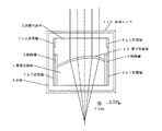
図6は、本実施形態におけるブレ補正装置の光学系を示す図である。図6において、図1と共通する構成には同一符号を付して重複説明を省略する。この図6での光学系は、光軸に対してシフトしない光学系群21,22と、光軸に対してシフトする液体レンズ120とから構成されている。この図6では、各光学系群の光軸がほぼ同軸上にある状態を示している。図6において、無限遠に対する像面は符号31で示す。
(Explanation of image blur correction by liquid lens)
Hereinafter, a specific example of correcting the image blur by controlling the liquid lens 120 will be described.
FIG. 6 is a diagram showing an optical system of the shake correction apparatus in the present embodiment. In FIG. 6, the same components as those in FIG. The optical system in FIG. 6 includes optical system groups 21 and 22 that do not shift with respect to the optical axis, and a liquid lens 120 that shifts with respect to the optical axis. FIG. 6 shows a state in which the optical axes of the optical system groups are substantially coaxial. In FIG. 6, the image plane for infinity is denoted by reference numeral 31.
図7は、図6のブレ補正装置に対して、液体レンズ120の上部電極7aと下部電極7bとの間、上部電極8aと下部電極8bとの間に、図4に示すドライバ80から出力された電圧を印加した状態を示している。この場合には、導電性液体1と誘電性液体2の界面形状を変化させることで、像面33の位置を図6に示す像面31とほぼ同一の位置(ピントが合った状態)にすることができる。
7 is output from the
1…導電性液体、2…誘電性液体、5…容器、6…絶縁層、7a,7b…上部電極、8a,8b…下部電極、13…第3物質層、15…角速度センサ、20…増幅部、30…A/D変換部、40…基礎値演算部、50…減算器、60…目標駆動値演算部、70…駆動量データテーブル、80…ドライバ、90…撮影倍率情報計算部、100…撮影距離情報計算部、110…ブレ補正レンズ光学情報計算部、115…ROM、120…液体レンズ、200…交換レンズ、210…カメラボディ、L…レンズ系(携帯電話)
DESCRIPTION OF
Claims (8)
前記第1液体とは異なる屈折率を有し誘電性を有する第2液体と、
前記第1液体と接触する第1面が前記第1液体と親和性を有し、前記第2液体と接触する第2面が前記第2液体と親和性を有し、前記第1液体の屈折率と前記第2液体の屈折率との間の屈折率を有する第1層と、
前記第1液体、前記第2液体及び前記第1層を収容する容器と、
絶縁層を介して前記第1液体に対向するように前記容器の内部に備えられた複数の第1電極と、
入射光の光軸方向に沿って前記第1電極と平行に備えられ、前記第2液体に対向するように前記容器の内部に備えられた複数の第2電極と、
装置のブレ量に対応するブレ検出信号に応じて前記第1電極および前記第2電極に印加する電圧を制御することにより、前記第1液体と前記第2液体との界面形状を変化させて像ブレを補正するブレ補正制御部とを備えることを特徴とするブレ補正装置。 A first liquid having electrical conductivity ;
And the second liquid body having a dielectric having a refractive index different from that of the first liquid member,
The first surface in contact with the first liquid has affinity with the first liquid, the second surface in contact with the second liquid has affinity with the second liquid, and the first liquid is refracted. a first layer which have a refractive index between the rate and the refractive index of the second liquid member,
A container containing the first liquid, the second liquid, and the first layer ;
A plurality of first electrodes provided inside the container so as to face the first liquid via an insulating layer;
A plurality of second electrodes provided in parallel to the first electrode along the optical axis direction of incident light and provided in the container so as to face the second liquid;
By controlling the voltage applied to the first electrode and the second electrode in accordance with a shake detection signal corresponding to the shake amount of the apparatus, the interface shape between the first liquid and the second liquid is changed, and the image is changed. shake correction apparatus, comprising a blur correction control unit for correcting the blur.
前記第1層は、前記第1液体および前記第2液体から分離して備えられていることを特徴とするブレ補正装置。 The blur correction device according to claim 1,
The first layer, motion compensation device, characterized in that provided separately from the first liquid member and said second liquid material.
前記第1層は、流動性を有することを特徴とするブレ補正装置。 The shake correction apparatus according to claim 1 or 2,
The blur correction device according to claim 1, wherein the first layer has fluidity.
前記第1層は、粘性体、液体、高分子膜および高分子粒のいずれか1つを含むことを特徴とするブレ補正装置。 The blur correction device according to any one of claims 1 to 3, wherein
The blur correction device , wherein the first layer includes any one of a viscous material , a liquid, a polymer film, and polymer particles.
前記第1液体、前記第2液体および前記第1層は、入射光の光軸に沿って配置されていることを特徴とするブレ補正装置。 The blur correction device according to any one of claims 1 to 4, wherein
The first liquid member, wherein the second fluid body and the first layer, blur correction apparatus characterized by being arranged along the optical axis of the incident light.
前記第1層は、入射光束に対する反射防止膜としての役割を有することを特徴とするブレ補正装置。 The blur correction device according to any one of claims 1 to 5, wherein
The blur correction device according to claim 1, wherein the first layer has a role as an antireflection film for an incident light beam.
入射光の波長をλとし、前記第1層の屈折率をnとしたとき、
前記第1層の厚さは、λ/(4n)であることを特徴とするブレ補正装置。 The blur correction device according to any one of claims 1 to 6, wherein
When the wavelength of incident light is λ and the refractive index of the first layer is n,
The blur correction device according to claim 1, wherein the thickness of the first layer is λ / (4n).
Priority Applications (1)
| Application Number | Priority Date | Filing Date | Title |
|---|---|---|---|
| JP2006165024A JP4894366B2 (en) | 2006-06-14 | 2006-06-14 | Blur correction device and optical apparatus |
Applications Claiming Priority (1)
| Application Number | Priority Date | Filing Date | Title |
|---|---|---|---|
| JP2006165024A JP4894366B2 (en) | 2006-06-14 | 2006-06-14 | Blur correction device and optical apparatus |
Publications (2)
| Publication Number | Publication Date |
|---|---|
| JP2007333975A JP2007333975A (en) | 2007-12-27 |
| JP4894366B2 true JP4894366B2 (en) | 2012-03-14 |
Family
ID=38933521
Family Applications (1)
| Application Number | Title | Priority Date | Filing Date |
|---|---|---|---|
| JP2006165024A Expired - Fee Related JP4894366B2 (en) | 2006-06-14 | 2006-06-14 | Blur correction device and optical apparatus |
Country Status (1)
| Country | Link |
|---|---|
| JP (1) | JP4894366B2 (en) |
Families Citing this family (7)
| Publication number | Priority date | Publication date | Assignee | Title |
|---|---|---|---|---|
| US8811914B2 (en) | 2009-10-22 | 2014-08-19 | At&T Intellectual Property I, L.P. | Method and apparatus for dynamically processing an electromagnetic beam |
| US8233673B2 (en) | 2009-10-23 | 2012-07-31 | At&T Intellectual Property I, L.P. | Method and apparatus for eye-scan authentication using a liquid lens |
| US8417121B2 (en) | 2010-05-28 | 2013-04-09 | At&T Intellectual Property I, L.P. | Method and apparatus for providing communication using a terahertz link |
| US8515294B2 (en) | 2010-10-20 | 2013-08-20 | At&T Intellectual Property I, L.P. | Method and apparatus for providing beam steering of terahertz electromagnetic waves |
| US11287553B2 (en) | 2017-01-09 | 2022-03-29 | Lg Innotek Co., Ltd. | Liquid lens |
| KR102692744B1 (en) * | 2017-06-30 | 2024-08-06 | 폴라이트 에이에스에이 | Lens assembly for optical image stabilization and focus adjustment |
| KR102720643B1 (en) * | 2019-01-25 | 2024-10-23 | 엘지이노텍 주식회사 | Liquid lens |
Family Cites Families (8)
| Publication number | Priority date | Publication date | Assignee | Title |
|---|---|---|---|---|
| JPH01302301A (en) * | 1988-05-31 | 1989-12-06 | Asahi Optical Co Ltd | Liquid enclosing optical element |
| JPH088942A (en) * | 1994-06-15 | 1996-01-12 | Mitsubishi Electric Corp | Multiple ring network equipment |
| JPH085942A (en) * | 1994-06-16 | 1996-01-12 | Canon Inc | Variable apex angle prism device |
| JP2002055286A (en) * | 2000-08-10 | 2002-02-20 | Canon Inc | Optical element and optical device having the same |
| JP4974677B2 (en) * | 2003-05-14 | 2012-07-11 | コーニンクレッカ フィリップス エレクトロニクス エヌ ヴィ | Variable shape lens |
| AU2005267561A1 (en) * | 2004-03-31 | 2006-02-02 | The Regents Of The University Of California | Fluidic adaptive lens |
| EP1733390B1 (en) * | 2004-03-31 | 2008-05-21 | Koninklijke Philips Electronics N.V. | Optical scanning device |
| JP4645523B2 (en) * | 2006-05-18 | 2011-03-09 | 株式会社ニコン | Optical device, shake correction device, camera system, interchangeable lens, mobile phone |
-
2006
- 2006-06-14 JP JP2006165024A patent/JP4894366B2/en not_active Expired - Fee Related
Also Published As
| Publication number | Publication date |
|---|---|
| JP2007333975A (en) | 2007-12-27 |
Similar Documents
| Publication | Publication Date | Title |
|---|---|---|
| EP2267512B1 (en) | Image blur reduction device and camera | |
| JP6438671B2 (en) | Focus adjustment apparatus, camera system, and focus adjustment method of imaging apparatus | |
| JP4488041B2 (en) | Image blur correction apparatus and imaging apparatus | |
| JP6523656B2 (en) | Focusing device and focusing method | |
| US8233786B2 (en) | Image shake correction apparatus and image pickup apparatus | |
| WO2015115124A1 (en) | Camera system | |
| WO2009093635A1 (en) | Lens tube, method of adjusting lens tube, method of manufacturing lens tube and imaging device | |
| KR20180076307A (en) | Method for Calibrating Driving Amount of Actuator Configured to Correct Blurring of Image Taken by Camera | |
| JP4894366B2 (en) | Blur correction device and optical apparatus | |
| JP2008241733A (en) | Imaging apparatus | |
| JP4973219B2 (en) | Optical equipment | |
| JP5458521B2 (en) | Lens barrel, lens barrel adjustment method, optical device, and optical device adjustment method | |
| JP2013054193A (en) | Shake correction device and optical apparatus | |
| JP2007127996A (en) | Blur correction device | |
| JP4951803B2 (en) | Camera shake correction control device, camera body including the same, and interchangeable lens | |
| JP4645523B2 (en) | Optical device, shake correction device, camera system, interchangeable lens, mobile phone | |
| KR20200014204A (en) | Control apparatus, imaging apparatus, and storage medium | |
| JP3135379B2 (en) | Image stabilization device | |
| JP2006308496A (en) | Ranging device and imaging device | |
| JP2022059763A (en) | Aberration correction method, program and imaging device | |
| JP2017011571A (en) | Image processing apparatus, image processing system, imaging apparatus, camera system, and image processing method | |
| JP2014215357A (en) | Image blur correction device and optical device | |
| JP2005326494A5 (en) | ||
| JP2012049892A (en) | Imaging apparatus | |
| TW200825622A (en) | Optical image taking structure |
Legal Events
| Date | Code | Title | Description |
|---|---|---|---|
| A621 | Written request for application examination |
Free format text: JAPANESE INTERMEDIATE CODE: A621 Effective date: 20090601 |
|
| A521 | Written amendment |
Free format text: JAPANESE INTERMEDIATE CODE: A523 Effective date: 20100204 |
|
| A131 | Notification of reasons for refusal |
Free format text: JAPANESE INTERMEDIATE CODE: A131 Effective date: 20110510 |
|
| A977 | Report on retrieval |
Free format text: JAPANESE INTERMEDIATE CODE: A971007 Effective date: 20110506 |
|
| A521 | Written amendment |
Free format text: JAPANESE INTERMEDIATE CODE: A523 Effective date: 20110711 |
|
| TRDD | Decision of grant or rejection written | ||
| A01 | Written decision to grant a patent or to grant a registration (utility model) |
Free format text: JAPANESE INTERMEDIATE CODE: A01 Effective date: 20111129 |
|
| A01 | Written decision to grant a patent or to grant a registration (utility model) |
Free format text: JAPANESE INTERMEDIATE CODE: A01 |
|
| A61 | First payment of annual fees (during grant procedure) |
Free format text: JAPANESE INTERMEDIATE CODE: A61 Effective date: 20111212 |
|
| R150 | Certificate of patent or registration of utility model |
Ref document number: 4894366 Country of ref document: JP Free format text: JAPANESE INTERMEDIATE CODE: R150 Free format text: JAPANESE INTERMEDIATE CODE: R150 |
|
| FPAY | Renewal fee payment (event date is renewal date of database) |
Free format text: PAYMENT UNTIL: 20150106 Year of fee payment: 3 |
|
| FPAY | Renewal fee payment (event date is renewal date of database) |
Free format text: PAYMENT UNTIL: 20150106 Year of fee payment: 3 |
|
| R250 | Receipt of annual fees |
Free format text: JAPANESE INTERMEDIATE CODE: R250 |
|
| R250 | Receipt of annual fees |
Free format text: JAPANESE INTERMEDIATE CODE: R250 |
|
| R250 | Receipt of annual fees |
Free format text: JAPANESE INTERMEDIATE CODE: R250 |
|
| R250 | Receipt of annual fees |
Free format text: JAPANESE INTERMEDIATE CODE: R250 |
|
| R250 | Receipt of annual fees |
Free format text: JAPANESE INTERMEDIATE CODE: R250 |
|
| R250 | Receipt of annual fees |
Free format text: JAPANESE INTERMEDIATE CODE: R250 |
|
| LAPS | Cancellation because of no payment of annual fees |