JP4958366B2 - Multiple bed pressure swing adsorption method and apparatus - Google Patents
Multiple bed pressure swing adsorption method and apparatus Download PDFInfo
- Publication number
- JP4958366B2 JP4958366B2 JP2001581959A JP2001581959A JP4958366B2 JP 4958366 B2 JP4958366 B2 JP 4958366B2 JP 2001581959 A JP2001581959 A JP 2001581959A JP 2001581959 A JP2001581959 A JP 2001581959A JP 4958366 B2 JP4958366 B2 JP 4958366B2
- Authority
- JP
- Japan
- Prior art keywords
- adsorber bed
- adsorber
- bed
- product gas
- gas
- Prior art date
- Legal status (The legal status is an assumption and is not a legal conclusion. Google has not performed a legal analysis and makes no representation as to the accuracy of the status listed.)
- Expired - Fee Related
Links
- 238000001179 sorption measurement Methods 0.000 title claims abstract description 14
- 238000000034 method Methods 0.000 title claims description 30
- IJGRMHOSHXDMSA-UHFFFAOYSA-N Atomic nitrogen Chemical compound N#N IJGRMHOSHXDMSA-UHFFFAOYSA-N 0.000 claims abstract description 52
- 238000010926 purge Methods 0.000 claims abstract description 31
- QVGXLLKOCUKJST-UHFFFAOYSA-N atomic oxygen Chemical compound [O] QVGXLLKOCUKJST-UHFFFAOYSA-N 0.000 claims abstract description 28
- 239000001301 oxygen Substances 0.000 claims abstract description 28
- 229910052760 oxygen Inorganic materials 0.000 claims abstract description 28
- 229910052757 nitrogen Inorganic materials 0.000 claims abstract description 26
- 239000007789 gas Substances 0.000 claims description 108
- 239000012080 ambient air Substances 0.000 claims description 20
- 230000008569 process Effects 0.000 claims description 18
- 239000003463 adsorbent Substances 0.000 claims description 8
- 238000004519 manufacturing process Methods 0.000 claims description 7
- 239000002699 waste material Substances 0.000 claims description 7
- 239000000203 mixture Substances 0.000 claims description 5
- 230000009467 reduction Effects 0.000 claims description 2
- 238000007599 discharging Methods 0.000 claims 1
- 239000003570 air Substances 0.000 description 12
- 239000000463 material Substances 0.000 description 9
- 230000008859 change Effects 0.000 description 3
- 238000010586 diagram Methods 0.000 description 3
- 239000012530 fluid Substances 0.000 description 3
- 239000008246 gaseous mixture Substances 0.000 description 3
- 238000012360 testing method Methods 0.000 description 3
- XKRFYHLGVUSROY-UHFFFAOYSA-N Argon Chemical compound [Ar] XKRFYHLGVUSROY-UHFFFAOYSA-N 0.000 description 2
- 238000013461 design Methods 0.000 description 2
- 230000007246 mechanism Effects 0.000 description 2
- 230000003584 silencer Effects 0.000 description 2
- 206010002091 Anaesthesia Diseases 0.000 description 1
- MYMOFIZGZYHOMD-UHFFFAOYSA-N Dioxygen Chemical compound O=O MYMOFIZGZYHOMD-UHFFFAOYSA-N 0.000 description 1
- DGAQECJNVWCQMB-PUAWFVPOSA-M Ilexoside XXIX Chemical compound C[C@@H]1CC[C@@]2(CC[C@@]3(C(=CC[C@H]4[C@]3(CC[C@@H]5[C@@]4(CC[C@@H](C5(C)C)OS(=O)(=O)[O-])C)C)[C@@H]2[C@]1(C)O)C)C(=O)O[C@H]6[C@@H]([C@H]([C@@H]([C@H](O6)CO)O)O)O.[Na+] DGAQECJNVWCQMB-PUAWFVPOSA-M 0.000 description 1
- BPQQTUXANYXVAA-UHFFFAOYSA-N Orthosilicate Chemical compound [O-][Si]([O-])([O-])[O-] BPQQTUXANYXVAA-UHFFFAOYSA-N 0.000 description 1
- PNEYBMLMFCGWSK-UHFFFAOYSA-N aluminium oxide Inorganic materials [O-2].[O-2].[O-2].[Al+3].[Al+3] PNEYBMLMFCGWSK-UHFFFAOYSA-N 0.000 description 1
- 230000037005 anaesthesia Effects 0.000 description 1
- 229910052786 argon Inorganic materials 0.000 description 1
- 230000001580 bacterial effect Effects 0.000 description 1
- 238000004891 communication Methods 0.000 description 1
- 230000003247 decreasing effect Effects 0.000 description 1
- 230000003111 delayed effect Effects 0.000 description 1
- 229910001882 dioxygen Inorganic materials 0.000 description 1
- 238000005194 fractionation Methods 0.000 description 1
- 238000012986 modification Methods 0.000 description 1
- 230000004048 modification Effects 0.000 description 1
- 239000002808 molecular sieve Substances 0.000 description 1
- 239000002245 particle Substances 0.000 description 1
- 230000001172 regenerating effect Effects 0.000 description 1
- 230000008929 regeneration Effects 0.000 description 1
- 238000011069 regeneration method Methods 0.000 description 1
- 229920006395 saturated elastomer Polymers 0.000 description 1
- 229910052708 sodium Inorganic materials 0.000 description 1
- 239000011734 sodium Substances 0.000 description 1
- URGAHOPLAPQHLN-UHFFFAOYSA-N sodium aluminosilicate Chemical compound [Na+].[Al+3].[O-][Si]([O-])=O.[O-][Si]([O-])=O URGAHOPLAPQHLN-UHFFFAOYSA-N 0.000 description 1
- 238000006467 substitution reaction Methods 0.000 description 1
- 230000000153 supplemental effect Effects 0.000 description 1
- 230000000007 visual effect Effects 0.000 description 1
- XLYOFNOQVPJJNP-UHFFFAOYSA-N water Chemical compound O XLYOFNOQVPJJNP-UHFFFAOYSA-N 0.000 description 1
Images

Classifications
-
- B—PERFORMING OPERATIONS; TRANSPORTING
- B01—PHYSICAL OR CHEMICAL PROCESSES OR APPARATUS IN GENERAL
- B01D—SEPARATION
- B01D53/00—Separation of gases or vapours; Recovering vapours of volatile solvents from gases; Chemical or biological purification of waste gases, e.g. engine exhaust gases, smoke, fumes, flue gases, aerosols
- B01D53/02—Separation of gases or vapours; Recovering vapours of volatile solvents from gases; Chemical or biological purification of waste gases, e.g. engine exhaust gases, smoke, fumes, flue gases, aerosols by adsorption, e.g. preparative gas chromatography
- B01D53/04—Separation of gases or vapours; Recovering vapours of volatile solvents from gases; Chemical or biological purification of waste gases, e.g. engine exhaust gases, smoke, fumes, flue gases, aerosols by adsorption, e.g. preparative gas chromatography with stationary adsorbents
- B01D53/047—Pressure swing adsorption
-
- B—PERFORMING OPERATIONS; TRANSPORTING
- B01—PHYSICAL OR CHEMICAL PROCESSES OR APPARATUS IN GENERAL
- B01D—SEPARATION
- B01D2253/00—Adsorbents used in seperation treatment of gases and vapours
- B01D2253/10—Inorganic adsorbents
- B01D2253/106—Silica or silicates
-
- B—PERFORMING OPERATIONS; TRANSPORTING
- B01—PHYSICAL OR CHEMICAL PROCESSES OR APPARATUS IN GENERAL
- B01D—SEPARATION
- B01D2256/00—Main component in the product gas stream after treatment
- B01D2256/12—Oxygen
-
- B—PERFORMING OPERATIONS; TRANSPORTING
- B01—PHYSICAL OR CHEMICAL PROCESSES OR APPARATUS IN GENERAL
- B01D—SEPARATION
- B01D2257/00—Components to be removed
- B01D2257/10—Single element gases other than halogens
- B01D2257/102—Nitrogen
-
- B—PERFORMING OPERATIONS; TRANSPORTING
- B01—PHYSICAL OR CHEMICAL PROCESSES OR APPARATUS IN GENERAL
- B01D—SEPARATION
- B01D2259/00—Type of treatment
- B01D2259/40—Further details for adsorption processes and devices
- B01D2259/40003—Methods relating to valve switching
-
- B—PERFORMING OPERATIONS; TRANSPORTING
- B01—PHYSICAL OR CHEMICAL PROCESSES OR APPARATUS IN GENERAL
- B01D—SEPARATION
- B01D2259/00—Type of treatment
- B01D2259/40—Further details for adsorption processes and devices
- B01D2259/40007—Controlling pressure or temperature swing adsorption
-
- B—PERFORMING OPERATIONS; TRANSPORTING
- B01—PHYSICAL OR CHEMICAL PROCESSES OR APPARATUS IN GENERAL
- B01D—SEPARATION
- B01D2259/00—Type of treatment
- B01D2259/40—Further details for adsorption processes and devices
- B01D2259/40011—Methods relating to the process cycle in pressure or temperature swing adsorption
- B01D2259/40058—Number of sequence steps, including sub-steps, per cycle
- B01D2259/40064—Five
-
- B—PERFORMING OPERATIONS; TRANSPORTING
- B01—PHYSICAL OR CHEMICAL PROCESSES OR APPARATUS IN GENERAL
- B01D—SEPARATION
- B01D2259/00—Type of treatment
- B01D2259/40—Further details for adsorption processes and devices
- B01D2259/40011—Methods relating to the process cycle in pressure or temperature swing adsorption
- B01D2259/40058—Number of sequence steps, including sub-steps, per cycle
- B01D2259/40066—Six
-
- B—PERFORMING OPERATIONS; TRANSPORTING
- B01—PHYSICAL OR CHEMICAL PROCESSES OR APPARATUS IN GENERAL
- B01D—SEPARATION
- B01D2259/00—Type of treatment
- B01D2259/40—Further details for adsorption processes and devices
- B01D2259/40011—Methods relating to the process cycle in pressure or temperature swing adsorption
- B01D2259/40077—Direction of flow
- B01D2259/40079—Co-current
-
- B—PERFORMING OPERATIONS; TRANSPORTING
- B01—PHYSICAL OR CHEMICAL PROCESSES OR APPARATUS IN GENERAL
- B01D—SEPARATION
- B01D2259/00—Type of treatment
- B01D2259/40—Further details for adsorption processes and devices
- B01D2259/40011—Methods relating to the process cycle in pressure or temperature swing adsorption
- B01D2259/40077—Direction of flow
- B01D2259/40081—Counter-current
-
- B—PERFORMING OPERATIONS; TRANSPORTING
- B01—PHYSICAL OR CHEMICAL PROCESSES OR APPARATUS IN GENERAL
- B01D—SEPARATION
- B01D2259/00—Type of treatment
- B01D2259/40—Further details for adsorption processes and devices
- B01D2259/403—Further details for adsorption processes and devices using three beds
-
- B—PERFORMING OPERATIONS; TRANSPORTING
- B01—PHYSICAL OR CHEMICAL PROCESSES OR APPARATUS IN GENERAL
- B01D—SEPARATION
- B01D2259/00—Type of treatment
- B01D2259/45—Gas separation or purification devices adapted for specific applications
- B01D2259/4533—Gas separation or purification devices adapted for specific applications for medical purposes
Landscapes
- Chemical & Material Sciences (AREA)
- Engineering & Computer Science (AREA)
- Analytical Chemistry (AREA)
- General Chemical & Material Sciences (AREA)
- Oil, Petroleum & Natural Gas (AREA)
- Chemical Kinetics & Catalysis (AREA)
- Separation Of Gases By Adsorption (AREA)
- Oxygen, Ozone, And Oxides In General (AREA)
- Separation By Low-Temperature Treatments (AREA)
- Superconductors And Manufacturing Methods Therefor (AREA)
- Magnetic Resonance Imaging Apparatus (AREA)
- Auxiliary Devices For And Details Of Packaging Control (AREA)
- Basic Packing Technique (AREA)
Abstract
Description
【0001】
【関連出願の相互参照】
本発明は、全体として、圧力スイング吸着法(「PSA」)により気体混合体を分離する気体濃縮装置、より具体的には、各種の工業用、商業用及び(又は)医療用目的のため、酸素を効率的に且つ静粛に製造する装置に関する。2000年5月10日付けで出願された出願係属中の仮特許出願第60/202,898号の優先権を主張するものである。
【0002】
【発明の背景】
本発明が関連する、PSAすなわち圧力スイング吸着装置の一般的な型式及び作動原理は、その他のもののうち、米国特許第3,564,816号、米国特許第3,636,679号、米国特許第3,717,974号、米国特許第4,802,899号、米国特許第5,531,807号及び米国特許第5,871,564号に記載されている。例えば、圧力スイング吸着装置は、2つ又はより多くの吸着器を備え、該吸着器の各々は供給流からの気体状混合体がその後に吸着器を通じて同一流れ方向に向けられるとき、床内に吸着することにより気体状混合体から少なくとも1つの成分気体を分画すべく吸着材料の固定のふるい床を有している。1つの吸着器が吸着を行う間、別の吸着器は、同時に、第1のすなわち製造吸着器から吸引され且つ他方の吸着器を通じて反対流れ方向に向けられる製品気体の一部にてその吸着した成分気体をパージする。他方の吸着器がパージされたならば、次に、予め設定した時点にて供給流は同一流れ方向に向けて他方の吸着器に向けられ、その他方の吸着器が吸着を行う。次に、第1の吸着器は、同時に又は2つ以上の吸着器がある場合、別の時間設定した順序にてパージされ、これらは全て上記の特許を読むことにより理解されるよう。
【0003】
例えば、医療用、工業用又は商業用であるかどうかを問わずに色々な用途にて使用するため、周囲空気から高濃度酸素を製造すべくかかる装置が使用されるとき、装置に入る空気は、典型的に、約78%の窒素、21%の酸素、0.9%のアルゴン、及び可変量の水蒸気を含んでいる。主として、窒素の殆どは装置によって除去され、医療目的のため、例えば、典型的に、少なくとも約80%の酸素を含む気体製品を発生させる。
【0004】
【発明の概要】
本発明は、新規で且つ改良された圧力スイング吸着(「PSA」又は「酸素濃縮器」)装置、特に、所望の用途に必要な酸素濃度を実現することができ、しかも、既知の多数床システムよりもより生産的で、よりエネルギ効率的で且つより静粛に作動する装置の作動方法を提供するものである。このことは、少なくとも一部分は、3つの床を超えない本発明の多数床PSA装置により及びそのときは製造作用をする「能動的」床により発生された有用な製品気体ではなくて、そのときは製造作用を行わない床すなわち「非能動的」床により発生された気体にて床がパージされる作動工程を含む作動サイクルにより実現される。
【0005】
本発明の上記及びその他の目的、特徴並びに有利な点は、本発明の1つの好ましい実施の形態についての添付図面に関する以下の説明を読むことにより、一層明らかになるであろう。
【0006】
【好ましい実施の形態の詳細な説明】
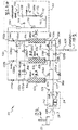
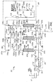
先ず、図面を参照すると、図1には、本発明に従って、圧力スイング吸着法により全体として周囲空気であるが必ずしもそれには限らない気体状混合体から少なくとも1つの成分、すなわち窒素を分画するのに使用される圧力スイング吸着すなわちPSA装置の1つの実施の形態が全体として参照番号20で図示されている。「AIR」で表示した気体状空気混合体は、吸気共振器58の粒子及び蒸気フィルタ21を通じて装置20に供給されて供給流の吸気の雑音を減少させる。供給流は共振器58からポンプ又はコンプレッサ組立体24により流体管106を通って流れる。電動コンプレッサ110、熱交換器108及び圧力逃がし弁112を保持するコンプレッサ組立体24は、供給流を流体管107を通じて連続的に移動させ、この流体管は、相応する供給弁116a、116b、116cを順次作動させることにより供給流を3つの入口管114a、114b、114cをそれぞれ通じて交互に且つ順次に送り得るように枝分かれしている。
【0007】
例えば、供給弁116aが開いているならば、供給流は、「同一流れ」方向すなわち、図1にて上方向に向けて第1の吸着器Aの入口82aに入る。吸着器A内に保持されたふるい床83aを通って流れるとき、供給流は、ふるい床83aにより吸着された供給流中の窒素の実質的な部分により、製品気体の所望の濃度に分画される一方、例えば、約95%の酸素から成る供給流の残りの部分は第1の吸着器Aの出口84aを通って製品気体として進行する。本明細書にて説明するように、吸着器は、装置のユーザに供給するため、製品気体を製造する一方、該吸着器は「能動的」床と称される一方、他方の床の各々は「非能動的」床と称される。
【0008】
吸着器A内の内部圧力が十分に高レベルであるとき、吸着器Aから出る製品気体の実質的な量は管150a及び共通の製品供給管150を通じて以下に説明する流れ制御組立体68に向けられ、ユーザに利用可能な有用な製品気体の一部を構成する。製品気体が制御組立体68から吸着器Aに逆流するのを防止し得るように逆止弁144aが管150内に配置されている。また、吸着器B、C内への逆流を防止するため相応する逆止弁144b、144cも設けられている。これらの逆止弁144a、144b、144cは、また、それぞれの吸着器の排出圧力が管圧に少なくとも等しい程度だけ高圧であり、これにより、吸着器床をより高圧で且つより効率的な圧力にて作動させるまで、そのそれぞれの吸着器から供給管150への製品気体の供給を遅らせるのに役立つ点で重要である。
【0009】
吸着器Aが能動的床として機能する間、吸着器Bは非能動的床であるが、吸着器Aの前に能動的床であった状態から依然として加圧される。本発明によれば、パージ制御弁136bcは開いて非能動的吸着器Bの加圧された気体を解放し、相応する偏向器の管132bcを通って流れ且つ非能動的吸着器床Cの出口84cを通じて反対流れ方向に流れてパージングを完了し且つ吸着器Cの再加圧を開始し、該吸着器のパージングは、吸着器Aが能動的吸着器となる直前に開始している。
【0010】
吸着器Aが能動的床である作動サイクルの部分の終了時、吸着器Aによって発生された製品気体の一部分は、またパージ制御弁136acを開けることにより偏向器の管132acを通じて非能動的吸着器Cに向けられ、吸着器Cの加圧を続行する。同一の時間順序にて、パージ制限弁136bcが閉じられ、排出弁120bが開放して吸着器B内に残る圧力を入口82bから出ることによりその吸着した窒素を放出し、図1に図示するように、適宜な音マフラー又は消音器126を通じて排気として管90bを通じて、雰囲気中に排出される。
【0011】
同様に、適宜なマイクロコントローラ(図示せず)により制御される弁の開放順序に依存して、管114c、114b内のそれぞれ相応する供給弁116c、116bを順次に開くことにより、吸着器床C、Bは順次に能動的床となり、ふるい床83c、83b内に製品気体を発生させ、この過程は、以下に説明するように順次に且つサイクルに対して繰り返される。
【0012】
管132を通って流れる偏向された製品気体の量を制御するため、吸着器を通じて反対流れ方向に製品気体の所望の量及び流れを一定にし得るように寸法を調節することのできる開口部を有する相応するパージオリフィス140ab、140ac、140bcが設けられている。図5の第2実施形態にて図示するように、偏向器の管132ab、132ac、132bcの各々と平行に管152ab、152bc、152ac内に別個に時間制御された双方向弁156ab、156ac、156bcを追加することにより、吸着器の間の圧力均衡率を調節することも可能である。この第2実施形態において、弁136の各々は、その相応する吸着器がパージされるとき、選択的に開放するが、パージが完了し、吸着器が再加圧されるとき、閉じられ、また、相応するオリフィス153ab、153ac、153bcが適宜な圧力均衡化工程を最適にし得る寸法である状態で相応する弁156は開放する。これと代替的に、第2実施形態における平行な偏向器の管152ab、152bc、152acは、特定のPSA能力の場合、偏向器の管132ab、132bc、132acを補助するために使用することができ、この場合、弁136は均衡化工程の間、閉じられず、オリフィス153ab、153ac、153bcは、PSA設計に対してより多量の流量を必要とするパージ又は均衡化工程に対し適宜な量の追加的な流れを追加することによりパージオリフィス140ab、140ac、140bcを通る流れを補充し得るような寸法とされている。
【0013】
3つの吸着器A、B、Cにより発生された製品気体の使用可能な部分を受け入れる流れ制御組立体68は、混合タンク154と、試験ブロック構成要素169と、圧力調整器170と、従来の流れ制御弁92と、逆止弁190aと、従来の細菌フィルタ198と、出口コネクタ100とを備えることができる。混合タンク154は、製品気体を所望の濃度に平均化するために使用することができる。混合タンク154を通ったならば、製品気体は、圧力を加えた状態で管167を通って向けられ且つ流れ制御弁92に達するまで、圧力調整器170によって監視される。次に、製品気体の流量は、流れ制御弁92により独立的に制御され、管172及び逆止弁192aを通って出口コネクタ100まで進む。また、代替的な又は補充的な気体供給源又は圧力を加えたメディキャストを装置に取り付けることができる逆止弁190bも図示されている。
【0014】
吸着器の各々が窒素にて飽和されたとき、弁は、順次に作動して、最初にそのそれぞれの供給弁116を閉じて、発生された製品気体の残りが該吸着器から出るとき、吸着器内の圧力を降下させる、すなわち減圧させる。部分的に減圧されたならば、その吸着器用の廃物弁すなわち出口弁120を開いて、別の非能動的吸着器内で再加圧状態で発生された製品気体の部分を適宜な弁順序により反対流れ方向に向けて流れるようにし第1の吸着器をパージし、第1の吸着器を再調節し、次の作動サイクルにて酸素濃縮した製品気体を適宜な順序で製造する。
【0015】
当該技術分野の当業者に明らかであるように、吸着器A、B、Cの各々は、適宜な支持構造体に取り付けられたほぼ細長い容器を備え、該容器は、貫通して供給される空気から窒素を吸収し得るようにされた吸着材料床でほぼ充填された内部キャビティを有している。更に、吸着器の各々の入口82a、82b、82c及び出口84a、84b、84cは、吸着材料床を通じて互いに流れ連通している。従って、同一流れ方向に向けて吸着器の入口82の各々内に向けられた空気の供給流れは、吸着材料に露呈され、これにより、空気中の窒素が吸着され、吸着器を再生するため、反対流れ方向(図1に示すように下方)に向けて流れる、偏向した製品気体によって、吸着された窒素は、吸着材料により解放され且つその廃物弁120a、120b、120cが開いたとき、そのそれぞれの入口82及び相応する排出管90a、90b、90cを通じて相応する吸着器から雰囲気中に排出される。
【0016】
吸着器A、B、Cの吸着器床は、例えば、20/40メッシュの床寸法を有するアルミナケイ酸ナトリウムとして既知の分子ふるい材料のような多数の適宜な吸着材料の任意のものから成るものとすることができる。特徴的に、吸着材料の型式及び量は、所望の濃度の製品酸素気体を発生させ得るように相応する吸着器A、B、C内にて処理された空気から適宜な量の窒素を吸収し得るように選ばれる。
【0017】
図示した実施の形態において、医療用途用の吸着器床の各々は、長さ約25.4cm(約10.0インチ)及び直径7.62cm(3.0インチ)であり、ふるい材料の重量は各々649gである。好ましくは、床は、床がその減圧又は圧力均衡化段階にあるとき、「流動化」しないようにばね偏倚させる。空気の供給流は約1.071scfmにて提供され、パージ管のオリフィス開口部は約1.321mm(約0.052)インチに設定される。理解し得るように、ぞれぞれのパージ制御弁136ab、136ac、136bcが開いたとき、「パワーパージ」相が開始されて吸着器A、B又はCは吸着器の別のものから排出気体を受け取り、オリフィスの寸法は、開放したパージ弁の影響を受ける床の圧力均衡化の程度を決定する。これと代替的に、パージ弁及びパージオリフィスの双方として機能し得るように、パージ弁136の座部を適宜に寸法設定し、また、図5の実施の形態の場合、オリフィス153を不要にし得るように弁156を適宜に寸法決めすることも可能である。
【0018】
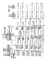
上述したように、2つの吸着器床を有するPSA装置を医療用途用に使用することも既知であり、この場合、吸着器の一方のみが任意の時点にて吸着を行う一方、他方の吸着器は再生を行う。医療用途用のかかる装置は、多くの状況にてかなり大型であるか、又は十分に静粛でないため、第3の吸着器床を導入することにより、及び図2及び図3に図示するように、これらより小さい寸法の床の使用を可能にし得るように最小の作動弁及び制御オリフィスの正確な順序及びタイミングを案出することにより、我々はこの問題点を解決した。
【0019】
図2に図示するように、本発明による3つの床PSA装置は、12の順次的な工程の各々の作動サイクルにて約93%酸素濃度の気体を分当たり約3リットル提供し得るように作動する。かかるサイクルの各々において、工程1(図示するように)は、吸着器Bから反対流れ方向に供給される高圧の偏向製品気体及び管114aからの同一流れ方向の供給流れの双方により、約62.053kPa(約9psi)から約96.527kPa(約14psi)まで再加圧される。これと同時に、供給弁116bが閉じられ、閉じた弁116bから吸着器Bに更なる供給流れ空気が提供されない状態にて、吸着器Bは、約155.132kPa(約22.5psi)から約137.895kPa(約20psi)まで減圧される過程にある。これと同時に且つ廃物弁120Cが開いた状態で吸着器C(それ以前のサイクルから製品気体を供給した後、早期にその減圧を開始している)は、約17.237kPa(約2.5psi)から約10.342kPa(約1.5psi)までのその減圧を完了する過程にある。
【0020】
次の工程2において、弁116a、136bc、120cは、約1.20秒の時間且つ本発明に従って開いている。この弁の作動順序により能動的吸着器Aは、約148.237kPa(約21.5psi)まで再加圧を続行する一方、該吸着器は製品気体を管150に供給し始め、ほぼこれと同時に、非能動的吸着器Bは、吸着器Cを通じて減圧され、この吸着器C内にて吸着器Bからの残りの製品気体は弁136bcを通じて吸着器Cに向けられ、吸着器Cを通って反対流れ方向に流れて、吸着器C内にそれ以前に吸着された窒素をパージし且つ排出する。この工程2から、より高圧が実現されるまで、製品気体の供給が遅延し、その結果、製品気体の純度が一層より均一になることが理解できる。
【0021】
工程3において、排出弁120cは、約1.0秒間、閉じられている。吸着器Bが約62.053kPa(約9.0psi)へのその減圧を続行し且つ吸着器Cへの製品気体の供給を続け、吸着器Cを約34.474kPa(約5.0psi)に再加圧する間、吸着器Aは製品気体の供給を続ける。
【0022】
工程4において、約0.8秒の間、弁116a、136ac、120bが開いた状態で、吸着器Aは管150aへの製品気体の供給を続行する一方、その気体の一部は吸着器Cの再加圧を続行し得るように吸着器Cに向けられる。弁120bのみが吸着器Bに対して開いた状態にて、吸着器B内に残る気体の一部は弁120bを通じて排出され、その内部圧力を約17.237kPa(約2.5psi)に減圧させる。
【0023】
理解し得るように、作動サイクルにおける最初の4つの工程間、吸着器Aは主として製品気体を供給すべく能動的吸着器であり、非能動的吸着器Bは、主として窒素を非能動的吸着器Cからパージし且つ該吸着器Cを再加圧するために使用される一方、吸着器Cは、そのパージサイクルを完了し且つ再加圧を開始する。
【0024】
同様に、工程5から8までにおいて、また、時間設定した工程及び相応する弁開放の同一の順序にて、吸着器Cは、主として製品気体を排出管150へ供給する能動的吸着器である一方、加圧され且つこのときは非能動的である吸着器A内の残りの製品気体は吸着器Bに向けられて、吸着器Bからその吸着した窒素をパージし且つこの吸着器の再加圧を開始する。
【0025】
最終工程9から12までにおいて、再度、同様の時間及び相応する弁順序にて、吸着器Bは、このときは能動的吸着器であり、非能動的吸着器Cからの加圧された気体は反対流れ方向に向けられて非能動的吸着器Aをパージし且つ該吸着器Aの再加圧を開始する。
【0026】
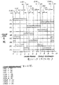
次に、装置の連続的な作動サイクルを通じて12の工程が繰り返される。
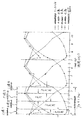
図3は、本発明に従って3床PSA装置を制御するために使用される色々な弁の時間設定した弁の開放順序(黒で図示)を示す別の図である。一方、図4には、12の工程サイクルの間、吸着器A、B、Cの各々における圧力の変化が示され、また、試験時点124における供給流れ供給管107内の作用可能な圧力及び調整器170の前方の試験箇所169における流れ制御装置68内の製品気体圧力の変化が示されている。
【0027】
図2及び図4から理解し得るように、好ましい実施の形態の結果、約3リットル/分(lpm)にて作動しているとき、約93%の酸素濃度の製品気体が3つの吸着器から供給されて少なくとも約131.000kPa(約19psi)及び約165.474kPa(約24psi)の高圧にて組立体68を制御する。従って、雰囲気空気供給流中酸素の少なくとも43から45%が製品気体に対して回収できる一方、典型的な2床酸素濃縮器は、空気から供給された酸素の約30から35%しか回収しない。この効率の増加は、一部分、当該3床システム内の吸着器が約62.053kPa(約9psi)だけ減圧することができる一方、典型的な2床システムは少なくとも約124.106kPa(約18psi)だけ減圧することを必要とするためである。より低い減圧圧力であれば、より小型の消音器のみがあればよいから、エネルギ効率は更に向上する。更に、典型的な2床システムは僅か約89.632kPa(約13psi)又は当該3床システムよりも約68.948kPa(約10psi)低い製品気体を供給する。
【0028】
本発明による酸素濃縮器内のより多量又はより小量の公称製品流量を提供するため、吸着器床の物理的寸法、すなわちその直径及び長さを変更し、また、空気供給流量及びパージオリフィスの寸法を調節することが可能である。作動サイクルにおける12の工程の各々に対する作動時間は、それに応じて、増加又は短縮するが、各サイクルの工程数及び各工程の機能は不変である。床寸法を決定する1つの関連する判断基準は、床の全長に亙って約6.895kPa(約1psi)圧力降下を維持することにある。このように、本発明による酸素濃縮器は、例えば、手術室及び麻酔並びに人工呼吸装置に使用される約344.738kPa(約50psi)の製品供給圧力のような、より多量の製造量の構造とすることが可能である。
【0029】
本発明による方法を使用すれば、PSA装置は、多岐に亙る目的、多岐に亙る作動パラメータ及び作動雰囲気にあった構造とすることができる。その効率及び静粛な作動のため、この装置は医療用の用途にて特に有用である。作動範囲は、68.948kPa(10psi)以下の最小値から689.476kPa(100psi)の最大値までの作動圧力とすることができ、サイクル時間は約3秒から約3分の範囲とし、約38%から約96%の酸素濃度の製品気体を製造する。本発明は、また該装置をより高圧力にて作動することも可能にし、このことは、吸着器床を一層より効率的なものにする。
【0030】
本発明による方法を使用するとき、2つの床のみを使用することも可能であり、この場合、パージ気体は非能動的吸着器ではなくて供給タンクによって提供され、供給タンクは余剰な製品気体にて充填される。しかし、3つの床を有する多数床システムは40%以上、より効率的であり、また、図4に図示するように、製品気体を作動サイクルの全体に亙ってより均一な酸素濃度にて供給し、これにより、濃度を平均化する混合タンクを不要にすることもできる設計を実現する。
【0031】
本発明による装置は概略図的にのみ図示されているが、当該技術分野の当業者は、本明細書に記載した本発明の説明から、従来の流体、電気及び電子構成要素及び当該技術分野にて周知の制御装置を使用して多数床PSA装置を製造することが可能であろう。更に、当該技術分野の当業者は、監視及び(又は)非監視状態の医療目的に使用されるとき、かかる装置に一般的である、視覚的表示計及び安全機能を含むことも可能であろう。製品気体中の酸素濃度を可変に制御することも望ましいならば、図示しないが、米国特許第5,871,564号に記載された、管132ab、132ac、132bcと平行に、一組みの第2の可調節型パージループを本発明に組み込むことが可能である。
【0032】
酸素濃縮器20の作動は、図2及び図3に図示したように、濃縮器20の弁手段の作動順序を見直すことにより理解することができる。装置の始動時、弁116、120、136の全ては開いて、全ての背圧を解消し、次に、図3に図示した順序にて、例えば、プログラマブル回路(図示せず)内に印刷された従来のスイッチ及びリレースイッチのタイミング機構を通じて開放し又は閉じたままにすることができる。供給弁、廃物弁及び均等化弁の各々は、弁への動力の供給開始又は遮断に応答可能なソレノイド型弁であることが好ましい。従って、供給弁、廃物弁及び均等化弁の各々が開き且つ閉じられる時間の長さを自動的に制御することにより、製品の製造及び再生作動は濃縮器20内で自動的に制御される。
【0033】
弁の制御に使用されるタイミング機構は、当該技術分野の当業者に既知の従来の回路及びスイッチを使用して設計することができ、コンプレッサ、スイッチ及び弁への動力は適宜な電気的接続により提供され、非常時は、補助電池装置により提供される。
【0034】
以下の説明から明らかであるように、装置20は、高酸素濃度の流れを発生させ得るように空気を分画するための圧力スイング吸着法の適用例に関して特に説明し且つ図示した。従って、装置20に対して使用される供給流は、圧縮した雰囲気空気である。本説明は所望の濃度の酸素製品気体を製造することに限定したが、当業者は、この圧力スイング吸着装置をその他の製品気体の製造に使用できることが明らかである。
【0035】
本発明の精神から逸脱せずに、説明した実施の形態に関し色々な改変及び置換を為すことが可能であることが理解されよう。例えば、吸着器の各々から管150への製品気体のタイミング及び供給を制御するため、逆止弁144a、144b、144cに代えて又はこれら逆止弁に加えて、タイミング設定したソレノイド弁を管150a、150b、150c内に含めることが可能である。従って、説明した実施の形態は説明することを目的とするものであり、限定的なものであることを意図するものではない。
【図面の簡単な説明】
【図1】 本発明によるPSA装置の概略図である。
【図2】 本発明によるPSA装置の作動工程の順序及びタイミングを示すチャートである。
2Aは、本発明によるPSA装置の作動工程の順序及びタイミングを示すチャートである。
2Bは、本発明によるPSA装置の作動工程の順序及びタイミングを示すチャートである。
【図3】 本発明によるPSA装置の作動を制御するために使用される弁のタイミングを示すチャートである。
【図4】 図1の装置の作動サイクル中の関連する圧力変化を示すグラフである。
【図5】 パージ及び圧力均衡化機能の双方を最適化し得るように選択的な製品気体偏向器の管を含む本発明の第2実施形態の概略図である。[0001]
[Cross-reference of related applications]
The present invention generally comprises a gas concentrator that separates a gas mixture by pressure swing adsorption ("PSA"), more specifically for various industrial, commercial and / or medical purposes, The present invention relates to an apparatus for efficiently and silently producing oxygen. This application claims priority from pending provisional patent application No. 60 / 202,898, filed May 10, 2000.
[0002]
BACKGROUND OF THE INVENTION
The general type and principle of operation of the PSA or pressure swing adsorption device to which the present invention is concerned is, among others, US Pat. No. 3,564,816, US Pat. No. 3,636,679, US Pat. No. 3,717,974, US Pat. No. 4,802,899, US Pat. No. 5,531,807 and US Pat. No. 5,871,564. For example, a pressure swing adsorber comprises two or more adsorbers, each of which is in the bed when the gaseous mixture from the feed stream is subsequently directed in the same flow direction through the adsorber. It has a fixed sieve bed of adsorbent material to fractionate at least one component gas from the gaseous mixture by adsorption. While one adsorber is adsorbing, another adsorber simultaneously adsorbed it with a portion of the product gas that is aspirated from the first or production adsorber and directed in the opposite flow direction through the other adsorber. Purge component gases. If the other adsorber is purged, then, at a preset time, the supply flow is directed toward the other adsorber in the same flow direction, and the other adsorber performs adsorption. The first adsorber is then purged at the same time or, if there are two or more adsorbers, in another time-set order, all as will be understood by reading the above patents.
[0003]
For example, when such a device is used to produce high concentrations of oxygen from ambient air for use in a variety of applications, whether medical, industrial or commercial, the air entering the device is Typically containing about 78% nitrogen, 21% oxygen, 0.9% argon, and variable amounts of water vapor. Primarily, most of the nitrogen is removed by the device, generating a gaseous product for medical purposes, for example, typically containing at least about 80% oxygen.
[0004]
SUMMARY OF THE INVENTION
The present invention provides a new and improved pressure swing adsorption (“PSA” or “oxygen concentrator”) device, in particular the oxygen concentration required for the desired application, and a known multiple bed system. It provides a method of operating a device that is more productive, more energy efficient and operates more quietly. This is not at least in part as a useful product gas generated by the multi-bed PSA apparatus of the present invention, which does not exceed three beds, and then by the “active” bed in production. This is accomplished by an operating cycle that includes an operating step in which the bed is purged with gas generated by a non-manufacturing bed or "inactive" bed.
[0005]
These and other objects, features and advantages of the present invention will become more apparent upon reading the following description of the accompanying drawings for one preferred embodiment of the present invention.
[0006]
[Detailed Description of Preferred Embodiments]
Referring initially to the drawings, FIG. 1 illustrates the fractionation of at least one component, ie, nitrogen, from a gaseous mixture that is generally, but not necessarily, ambient air according to the present invention by pressure swing adsorption. One embodiment of a pressure swing adsorption or PSA device used in the present invention is indicated generally by the
[0007]
For example, if the supply valve 116a is open, the supply flow enters the inlet 82a of the first adsorber A in the “same flow” direction, ie, upward in FIG. When flowing through
[0008]
When the internal pressure in adsorber A is at a sufficiently high level, a substantial amount of product gas exiting adsorber A is directed through a tube 150a and a common
[0009]
While adsorber A functions as an active bed, adsorber B is an inactive bed, but is still pressurized from the state that it was the active bed before adsorber A. In accordance with the present invention, the purge control valve 136bc opens to release the pressurized gas of the inactive adsorber B, flows through the corresponding deflector tube 132bc, and exits the inactive adsorber bed C. 84c completes purging and begins to repressurize adsorber C, which begins immediately before adsorber A becomes the active adsorber.
[0010]
At the end of the part of the operating cycle in which adsorber A is the active bed, a portion of the product gas generated by adsorber A is also deactivated through deflector tube 132ac by opening purge control valve 136ac. Continue to pressurize the adsorber C. In the same time sequence, the purge limiting valve 136bc is closed, the
[0011]
Similarly, the adsorber bed C can be opened by sequentially opening the
[0012]
To control the amount of deflected product gas flowing through tube 132, it has an opening that can be sized to allow the desired amount and flow of product gas to be constant in the opposite flow direction through the adsorber. Corresponding purge orifices 140ab, 140ac, 140bc are provided. As illustrated in the second embodiment of FIG. 5, separately time-controlled bi-directional valves 156ab, 156ac, 156bc in the tubes 152ab, 152bc, 152ac in parallel with each of the deflector tubes 132ab, 132ac, 132bc. It is also possible to adjust the pressure balance ratio between the adsorbers by adding. In this second embodiment, each of the valves 136 is selectively opened when its corresponding adsorber is purged, but is closed when the purge is complete and the adsorber is repressurized, and The corresponding valve 156 is opened with the corresponding orifices 153ab, 153ac, 153bc being sized to optimize the appropriate pressure balancing process. Alternatively, the parallel deflector tubes 152ab, 152bc, 152ac in the second embodiment can be used to assist the deflector tubes 132ab, 132bc, 132ac for certain PSA capabilities. In this case, the valve 136 is not closed during the balancing process and the orifices 153ab, 153ac, 153bc add an appropriate amount to the purge or balancing process that requires a higher flow rate for the PSA design. The dimensions are such that the flow through purge orifices 140ab, 140ac, 140bc can be replenished by adding additional flow.
[0013]
A
[0014]
When each of the adsorbers is saturated with nitrogen, the valves operate in sequence, initially closing their respective supply valves 116 and adsorbing when the remainder of the generated product gas exits the adsorber. The pressure in the vessel is reduced, i.e. reduced. Once partially depressurized, the adsorber waste or outlet valve 120 is opened and the portion of product gas generated in the repressurized state in another inactive adsorber is placed in the appropriate valve sequence. The first adsorber is purged to flow in the opposite flow direction, the first adsorber is readjusted, and oxygen enriched product gas is produced in the appropriate sequence in the next operating cycle.
[0015]
As will be apparent to those skilled in the art, each of the adsorbers A, B, C comprises a generally elongated container attached to a suitable support structure, the container being supplied with air supplied therethrough. Having an internal cavity substantially filled with a bed of adsorbent material adapted to absorb nitrogen. Furthermore, each
[0016]
The adsorber beds of adsorbers A, B, C consist of any of a number of suitable adsorbent materials such as, for example, a molecular sieve material known as sodium alumina silicate having a bed size of 20/40 mesh. It can be. Characteristically, the type and amount of adsorbent material absorbs an appropriate amount of nitrogen from the air treated in the corresponding adsorbers A, B, C so as to generate the desired concentration of product oxygen gas. Chosen to get.
[0017]
In the illustrated embodiment, each adsorber bed for medical use is approximately 10.0 inches in length and 3.0 inches in diameter, and the weight of the sieve material is Each is 649 g. Preferably, the bed is spring biased so that it does not "fluidize" when the bed is in its reduced pressure or pressure balancing stage. The air supply flow is provided at about 1.071 scfm and the orifice opening of the purge tube is set to about 0.052 inches. As can be appreciated, when each purge control valve 136ab, 136ac, 136bc is opened, a "power purge" phase is initiated and adsorber A, B or C is exhausted from another of the adsorbers. The size of the orifice determines the degree of pressure balancing of the bed affected by the open purge valve. Alternatively, the seat of the purge valve 136 can be appropriately sized so that it can function as both a purge valve and a purge orifice , and the orifice 153 can be dispensed with in the embodiment of FIG. Thus, the valve 156 can be appropriately dimensioned.
[0018]
As mentioned above, it is also known to use a PSA device with two adsorber beds for medical purposes, in which case only one of the adsorbers performs adsorption at any point in time while the other adsorber Does playback. Such devices for medical applications are quite large in many situations or are not sufficiently quiet, so by introducing a third adsorber bed and as illustrated in FIGS. We have solved this problem by devising the exact sequence and timing of minimal actuating valves and control orifices to allow the use of floors of these smaller dimensions.
[0019]
As illustrated in FIG. 2, the three bed PSA apparatus according to the present invention operates to provide approximately 93 liters per minute of gas with approximately 93% oxygen concentration in each operating cycle of 12 sequential processes. To do. In each such cycle, step 1 (as shown) involves approximately 62... By both the high pressure deflected product gas supplied from adsorber B in the opposite flow direction and the same flow direction supply flow from
[0020]
In the
[0021]
In
[0022]
In
[0023]
As can be seen, during the first four steps in the operating cycle, adsorber A is an active adsorber primarily to supply product gas, and inactive adsorber B is primarily an inactive adsorber. While being purged from C and used to repressurize the adsorber C, adsorber C completes its purge cycle and begins repressurization.
[0024]
Similarly, in
[0025]
In the
[0026]
The twelve steps are then repeated throughout the continuous operating cycle of the device.
FIG. 3 is another diagram illustrating the timed valve opening sequence (shown in black) of the various valves used to control a three-bed PSA device in accordance with the present invention. On the other hand, FIG. 4 shows the change in pressure in each of the adsorbers A, B, C during twelve process cycles, and the operable pressure and regulation in the supply
[0027]
As can be seen from FIGS. 2 and 4, as a result of the preferred embodiment, when operating at about 3 liters per minute (lpm), a product gas with an oxygen concentration of about 93% is drawn from the three adsorbers. As supplied, the
[0028]
In order to provide a higher or lower nominal product flow rate within the oxygen concentrator according to the present invention, the physical dimensions of the adsorber bed, i.e. its diameter and length, are changed, and the air supply flow rate and purge orifice It is possible to adjust the dimensions. The operating time for each of the 12 processes in the operating cycle is increased or decreased accordingly, but the number of processes in each cycle and the function of each process is unchanged. One relevant criterion for determining floor dimensions is to maintain a pressure drop of about 1 psi throughout the length of the bed. Thus, the oxygen concentrator according to the present invention has a higher production volume structure such as, for example, about 50 psi of product supply pressure used in operating rooms and anesthesia and ventilators. Is possible.
[0029]
Using the method according to the present invention, the PSA device can be structured to suit a wide variety of purposes, a wide variety of operating parameters, and a working atmosphere. Due to its efficiency and quiet operation, this device is particularly useful in medical applications. The operating range can be from a minimum value of 68.948 kPa (10 psi) or less to a maximum value of 689.476 kPa (100 psi), the cycle time can range from about 3 seconds to about 3 minutes, and about 38 % To about 96% oxygen product gas is produced. The present invention also allows the apparatus to operate at higher pressures, which makes the adsorber bed even more efficient.
[0030]
When using the method according to the invention, it is also possible to use only two beds, in which case the purge gas is provided by a supply tank rather than an inactive adsorber, the supply tank being used for excess product gas. Filled. However, a multi-bed system with three beds is more than 40% more efficient and supplies product gas at a more uniform oxygen concentration throughout the operating cycle, as illustrated in FIG. This realizes a design that can eliminate the need for a mixing tank that averages the concentration.
[0031]
Although the apparatus according to the present invention is shown schematically only, those skilled in the art will be able to understand conventional fluid, electrical and electronic components and the art from the description of the invention described herein. It would be possible to produce a multi-bed PSA device using known control devices. Furthermore, those skilled in the art could also include visual indicators and safety features that are common to such devices when used for supervised and / or unsupervised medical purposes. . If it is also desirable to variably control the oxygen concentration in the product gas, although not shown, a second set of second parallel to tubes 132ab, 132ac, 132bc described in US Pat. No. 5,871,564. Can be incorporated into the present invention.
[0032]
The operation of the
[0033]
The timing mechanism used to control the valve can be designed using conventional circuits and switches known to those skilled in the art, and the power to the compressor, switch and valve is via appropriate electrical connections. Provided, in case of emergency, provided by an auxiliary battery device.
[0034]
As will be apparent from the description below, the
[0035]
It will be understood that various modifications and substitutions can be made to the described embodiments without departing from the spirit of the invention. For example, in order to control the timing and supply of product gas from each of the adsorbers to the
[Brief description of the drawings]
FIG. 1 is a schematic diagram of a PSA device according to the present invention.
FIG. 2 is a chart showing the sequence and timing of the operation steps of the PSA device according to the present invention.
2A is a chart showing the sequence and timing of the operation steps of the PSA device according to the present invention.
2B is a chart showing the sequence and timing of the operation steps of the PSA device according to the present invention.
FIG. 3 is a chart showing the timing of the valves used to control the operation of the PSA device according to the present invention.
4 is a graph showing the associated pressure change during the operating cycle of the apparatus of FIG. 1. FIG.
FIG. 5 is a schematic diagram of a second embodiment of the present invention including a selective product gas deflector tube so that both purge and pressure balancing functions can be optimized.
Claims (6)
前記製品気体は、
(a)第1の吸着器床(C)に吸着された成分気体をパージする工程の完了後に、第2の吸着器床(B)からの加圧された製品気体を用いて第1の吸着器床(C)を中間的に加圧しながら、第3の吸着器床(A)から使用可能な製品気体の出口への供給を続け(工程3)、
(b)第3の吸着器床(A)によって使用可能な製品気体を製造しながら、第3の吸着器床(A)からの加圧された製品気体を用いて第1の吸着器床(C)の中間的加圧を継続し(工程4)、
(c)第3の吸着器床(A)がもはや製品気体を出口に提供しなくなった後には、第3の吸着器床(A)からの気体で第1の吸着器床(C)の加圧を継続する(工程5)、
各工程を含むサイクルで製造する、方法。Three adsorber beds (C, B, A) are provided so that at least one component gas can be adsorbed from the feed gas mixture, and the feed gas mixture is alternately and sequentially passed through each of the adsorber beds in the same flow direction. Is fed to the outlet (100) of the apparatus by adsorbing at least a substantial portion of the component gas and purging the component gas adsorbed by the pressurized gas supplied in the opposite flow direction. In a method for producing a product gas concentrated in a pressure swing adsorption device from a feed gas mixture, wherein usable product gas is produced in a cycle,
The product gas is
(A) After completion of the step of purging the component gas adsorbed on the first adsorber bed (C) , the first adsorption using the pressurized product gas from the second adsorber bed (B) Continue to feed the usable product gas from the third adsorber bed (A) to the outlet while intermediately pressurizing the bed (C) (step 3),
(B) Using the pressurized product gas from the third adsorber bed (A) to produce a usable product gas by the third adsorber bed (A), the first adsorber bed ( C) the intermediate pressurization is continued (step 4),
(C) After the third adsorber bed (A) no longer provides product gas to the outlet, the gas from the third adsorber bed (A) is added to the first adsorber bed (C). Continue the pressure (step 5),
A method of manufacturing in a cycle including each step.
(a)周囲空気内の窒素の少なくとも大部分を吸着するために周囲空気を第1の吸着器床(C)を通して同一流れ方向に供給し、第1の吸着器床を通過した気体を酸素濃縮製品気体として装置の出口へ送り出し、それと同時に第1の吸着器床(C)の気体圧力を上昇した作動圧力まで高め、それとほぼ同時に第2の吸着器床(B)を加圧するプロセスを開始するために第2の吸着器床(B)を通して反対流れ方向に供給されるべき第3の吸着器床(A)からの加圧された製品ガスを第2吸着器床(B)に向け、それと同時に第3の吸着器床(A)が減圧されると共に、第2の吸着器床(B)から吸着された窒素をパージする工程を完了させ(工程6)、
(b)第2の吸着器床から吸着された窒素をパージする工程の終了後に、第3の吸着器床からの製品気体によって第2の吸着器床を再加圧するプロセスを継続し、(工程7)、
(c)第1の吸着器床を、上昇した作動圧力から減圧を開始するようにすると共に、第1の吸着器床からの製品気体を装置の出口に送り出すが、第2の吸着器床の再加圧を継続するために第1の吸着器床からの製品気体の一部を第2の吸着器床に供給し、それと略同時に第3の吸着器床に吸着された窒素を排出させながら第3の吸着器床の減圧を継続し(工程8)、
(d)周囲空気および第1の吸着器床からの製品気体の両方によって第2の吸着器床の再加圧を継続するために、第2の吸着器床へ製品気体に加えて周囲空気を供給し(工程9)、
(e)周囲空気内の窒素の少なくとも大部分を吸着するために同一流れ方向で第2の吸着器床への周囲空気の供給を継続し、第2の吸着器床を通過した気体を酸素濃縮製品気体として装置の出口に送り出し、それと同時に第2の吸着器床の気体圧力を上昇した作動圧力まで高め、それとほぼ同時に第1の吸着器床が減圧され第3の吸着器床からの吸着された窒素のパージが完了すると共に、第3の吸着器床の再加圧プロセスを開始するために第1の吸着器床からの加圧された製品気体を反対流れ方向で第3の吸着器床へ供給されるように向けて(工程10)、
(f)第3の吸着器床からの吸着された窒素のパージ工程が完了した後に、第1の吸着器床からの製品気体で第3の吸着器床を再加圧するプロセスを継続し(工程11)、
(g)第2の吸着器床から装置出口へ製品気体の供給を継続するが、第3の吸着器床の再加圧を継続するために、第2の吸着器床からの製品気体の一部を第3の吸着器床に分配しながら、第2の吸着器床が上昇した作動圧力から減圧を開始するのを許容し、それとほぼ同時に第1の吸着器床に吸着された窒素を排出しながら第1の吸着器床の減圧を継続し(工程12)、
(h)周囲空気および第2の吸着器床からの製品気体の両方によって第3の吸着器床の再加圧を継続するために、第3の吸着器床へ製品気体に加えて周囲空気を供給し(工程1)、
(i)周囲空気内の窒素の少なくとも大部分を吸着するために同一流れ方向で第3の吸着器床への周囲空気の供給を継続し、第3の吸着器床を通過した気体を酸素濃縮製品気体として装置の出口に送り出し、それと同時に第3の吸着器床の気体圧力を上昇した作動圧力まで高め、それとほぼ同時に第2の吸着器床が減圧され第1の吸着器床からの吸着された窒素のパージが完了すると共に、第1の吸着器床の再加圧プロセスを開始するために第2の吸着器床からの加圧された製品気体を反対流れ方向で第1の吸着器床へ供給されるように向けて(工程2)、
(j)第1の吸着器床からの吸着された窒素のパージ工程が終了した後に、第2の吸着器床からの製品気体で第1の吸着器床を再加圧するプロセスを継続し、(工程3)、
(k)第3の吸着器床から装置出口へ製品気体の供給を継続するが、第1の吸着器床の再加圧を継続するために、第3の吸着器床からの製品気体の一部を第1の吸着器床に分配しながら、第3の吸着器床が上昇した作動圧力から減圧を開始するのを許容し、それとほぼ同時に第2の吸着器床に吸着された窒素を排出させながら第2の吸着器床の減圧を継続し(工程4)、
(l)周囲空気および第3の吸着器床からの製品気体の両方によって第1の吸着器床の再加圧を継続するために、第1の吸着器床へ製品気体に加えて周囲空気を供給する(工程5)、各ステップを含み、
(m)装置の出口への酸素濃縮気体の供給継続の要求に応じて、ステップ(a)〜(l)を繰り返す、方法。2. The method of claim 1 for producing oxygen enriched gas from ambient air, wherein the adsorber bed includes a nitrogen adsorbent and delivers oxygen enriched gas to the outlet of the apparatus, each cycle comprising 12 cycles. Including steps,
(A) Ambient air is supplied in the same flow direction through the first adsorber bed (C) in order to adsorb at least most of the nitrogen in the ambient air, and the gas that has passed through the first adsorber bed is enriched with oxygen. As the product gas is sent to the outlet of the apparatus, at the same time the gas pressure of the first adsorber bed (C) is increased to the increased working pressure and at the same time the process of pressurizing the second adsorber bed (B) is started. Directing the pressurized product gas from the third adsorber bed (A) to be fed in the opposite flow direction through the second adsorber bed (B) to the second adsorber bed (B), and At the same time, the third adsorber bed (A) is depressurized and the step of purging nitrogen adsorbed from the second adsorber bed (B) is completed (step 6).
(B) After completion of the step of purging nitrogen adsorbed from the second adsorber bed, the process of repressurizing the second adsorber bed with the product gas from the third adsorber bed is continued (step 7),
(C) The first adsorber bed is started to depressurize from the increased operating pressure, and the product gas from the first adsorber bed is sent to the outlet of the apparatus. In order to continue the repressurization, a part of the product gas from the first adsorber bed is supplied to the second adsorber bed, and at the same time, the nitrogen adsorbed on the third adsorber bed is discharged. Continue depressurizing the third adsorber bed (step 8),
(D) In order to continue repressurization of the second adsorber bed with both ambient air and product gas from the first adsorber bed, ambient air is added to the second adsorber bed in addition to product gas. Supply (step 9),
(E) In order to adsorb at least most of the nitrogen in the ambient air, the supply of the ambient air to the second adsorber bed is continued in the same flow direction, and the gas passing through the second adsorber bed is concentrated with oxygen. At the same time, the gas pressure in the second adsorber bed is increased to the increased operating pressure, and at the same time, the first adsorber bed is depressurized and adsorbed from the third adsorber bed. As the nitrogen purge is completed, the pressurized product gas from the first adsorber bed is flowed in the reverse flow direction to initiate the third adsorber bed repressurization process. towards as supplied to (step 10),
(F) The process of repressurizing the third adsorber bed with product gas from the first adsorber bed is continued after the purge step of adsorbed nitrogen from the third adsorber bed is completed (step 11),
(G) The supply of product gas from the second adsorber bed to the apparatus outlet is continued, but in order to continue repressurization of the third adsorber bed, one of the product gases from the second adsorber bed Allow the second adsorber bed to start depressurization from the increased operating pressure while distributing the part to the third adsorber bed, and exhaust the nitrogen adsorbed on the first adsorber bed almost simultaneously While continuing to depressurize the first adsorber bed (step 12),
(H) In order to continue repressurization of the third adsorber bed with both ambient air and product gas from the second adsorber bed, ambient air in addition to product gas to the third adsorber bed Supply (step 1),
(I) In order to adsorb at least most of the nitrogen in the ambient air, the supply of the ambient air to the third adsorber bed is continued in the same flow direction, and the gas passing through the third adsorber bed is enriched with oxygen. At the same time, the gas pressure in the third adsorber bed is increased to the increased operating pressure, and at the same time, the second adsorber bed is depressurized and adsorbed from the first adsorber bed. As the nitrogen purge is completed, the first adsorber bed in the opposite flow direction is fed with pressurized product gas from the second adsorber bed to initiate the first adsorber bed repressurization process. towards as supplied to the (step 2),
(J) continuing the process of re-pressurizing the first adsorber bed with product gas from the second adsorber bed after the purge step of adsorbed nitrogen from the first adsorber bed is completed ( Step 3),
(K) The supply of product gas from the third adsorber bed to the apparatus outlet is continued, but in order to continue the pressurization of the first adsorber bed, the product gas from the third adsorber bed Allow the third adsorber bed to start depressurizing from the raised operating pressure while discharging the nitrogen adsorbed on the second adsorber bed almost simultaneously is allowed while continuing the second adsorber bed pressure reduction (step 4),
(L) In order to continue repressurization of the first adsorber bed with both ambient air and product gas from the third adsorber bed, ambient air is added to the first adsorber bed in addition to product gas. Supplying (step 5), including each step,
(M) A method in which steps (a) to (l) are repeated in response to a request to continue supplying oxygen-enriched gas to the outlet of the apparatus.
前記12個の工程は作動弁によって制御されるものであり、
工程(a)、(e)および(i)のそれぞれは1つの吸着器床に周囲空気を供給するために各吸着器床の一つに開いている供給弁(116)と、残りの2つの吸着器床のうちの一方を残りの吸着器床の他方によって再加圧するために残りの2つの吸着器床の間に開いている平衡弁(136)と、残りの2つの吸着器床のうちの一方に開いている廃棄弁(120)とを用い、
工程(b)、(f)および(j)のそれぞれは、1つの吸着器床に開いている供給弁と、残りの2つの吸着器床の間に開いている平衡弁とを用い、
工程(c)、(g)および(k)のそれぞれは、1つの吸着器床に開いている周囲空気供給弁と、残りの2つの吸着器床のうちの1つを再加圧を継続するための1つの吸着器床と残りの2つの吸着器床のうちの一方との間に開いている平衡弁と、残りの2つの吸着器床のうちの他方に開いている廃棄弁とを用い、
工程(d)、(h)および(l)のそれぞれは、残りの2つの吸着器床のうちの1つに開いている周囲空気供給弁と、残りの2つの吸着器床の一方の圧力を高めるために1つの吸着器床と残りの2つの吸着器床のうちの一方との間および出口に開いている平衡弁と、開いたままの残りの2つの吸着器床の他方に開いている排気弁とを用いる、
方法。The method of claim 5, wherein
The twelve steps are controlled by operating valves,
Each of steps (a), (e) and (i) includes a supply valve (116) open to one of each adsorber bed to supply ambient air to one adsorber bed, and the remaining two A balance valve (136) open between the remaining two adsorber beds to repressurize one of the adsorber beds with the other of the remaining adsorber beds, and one of the remaining two adsorber beds And a waste valve (120) open to
Each of steps (b), (f) and (j) uses a feed valve open to one adsorber bed and a balance valve open between the remaining two adsorber beds,
Each of steps (c), (g) and (k) continues to repressurize the ambient air supply valve open to one adsorber bed and one of the remaining two adsorber beds. A balance valve that is open between one adsorber bed and one of the remaining two adsorber beds and a waste valve that is open on the other of the remaining two adsorber beds ,
Each of steps (d), (h), and (l) involves the opening of an ambient air supply valve to one of the remaining two adsorber beds and the pressure of one of the remaining two adsorber beds. An open balance valve between one adsorber bed and one of the remaining two adsorber beds to increase and at the outlet and open to the other of the remaining two adsorber beds that remain open Using an exhaust valve,
Method.
Applications Claiming Priority (3)
| Application Number | Priority Date | Filing Date | Title |
|---|---|---|---|
| US20289800P | 2000-05-10 | 2000-05-10 | |
| US60/202,898 | 2000-05-10 | ||
| PCT/US2001/015053 WO2001085309A1 (en) | 2000-05-10 | 2001-05-10 | Multiple bed pressure swing adsorption method and apparatus |
Publications (3)
| Publication Number | Publication Date |
|---|---|
| JP2003532519A JP2003532519A (en) | 2003-11-05 |
| JP2003532519A5 JP2003532519A5 (en) | 2008-10-09 |
| JP4958366B2 true JP4958366B2 (en) | 2012-06-20 |
Family
ID=22751674
Family Applications (1)
| Application Number | Title | Priority Date | Filing Date |
|---|---|---|---|
| JP2001581959A Expired - Fee Related JP4958366B2 (en) | 2000-05-10 | 2001-05-10 | Multiple bed pressure swing adsorption method and apparatus |
Country Status (9)
| Country | Link |
|---|---|
| US (1) | US6558451B2 (en) |
| EP (1) | EP1283739B1 (en) |
| JP (1) | JP4958366B2 (en) |
| AT (1) | ATE368500T1 (en) |
| AU (1) | AU2001261349A1 (en) |
| CA (1) | CA2408273C (en) |
| DE (1) | DE60129685T2 (en) |
| ES (1) | ES2290133T3 (en) |
| WO (1) | WO2001085309A1 (en) |
Families Citing this family (62)
| Publication number | Priority date | Publication date | Assignee | Title |
|---|---|---|---|---|
| GB0123310D0 (en) * | 2001-09-28 | 2001-11-21 | Honeywell Normalair Garrett | Breathing gas supply system |
| KR100495974B1 (en) * | 2002-01-16 | 2005-06-17 | 디지털오토모빌(주) | Air purification device with oxygen-supplying function, for automobiles |
| JP4473580B2 (en) * | 2002-01-31 | 2010-06-02 | エアーセップ・コーポレーション | Portable oxygen concentrator |
| GB0204886D0 (en) * | 2002-03-01 | 2002-04-17 | Honeywell Normalair Garrett | Breathing gas supply system |
| KR100491684B1 (en) * | 2002-04-12 | 2005-05-30 | 주식회사 옥서스 | Gas concentrating Method and apparatus for use of Pressure Swing Adsorption |
| ATE357962T1 (en) * | 2002-04-24 | 2007-04-15 | Airsep Corp | OXYGEN CONCENTRATOR WITH REDUCED NOISE LEVEL |
| DE10245042B4 (en) * | 2002-09-26 | 2007-09-27 | DRäGER AEROSPACE GMBH | Apparatus for enriching air oxygen |
| US6699307B1 (en) * | 2002-10-11 | 2004-03-02 | H2Gen Innovations, Inc. | High recovery PSA cycles and apparatus with reduced complexity |
| US6866701B2 (en) * | 2002-11-26 | 2005-03-15 | Udi Meirav | Oxygen enrichment of indoor human environments |
| WO2004054493A2 (en) * | 2002-12-12 | 2004-07-01 | Airsep Corporation | Portable hypoxic apparatus |
| US20040211414A1 (en) * | 2003-04-28 | 2004-10-28 | Litton Systems, Inc. | Oxygen concentration system having selectable beds |
| AU2003263649A1 (en) * | 2003-05-27 | 2005-01-21 | Samsun Corporation | Oxygen generator |
| US6887301B2 (en) * | 2003-06-04 | 2005-05-03 | H2Gen Innovations, Inc. | Flow control in pressure swing adsorption systems |
| US6959728B2 (en) * | 2003-09-02 | 2005-11-01 | Airsep Corporation | Rotary cam valve |
| JP4796492B2 (en) | 2003-09-02 | 2011-10-19 | エアーセップ・コーポレーション | Sound container for portable oxygen concentrator |
| EP1680199A4 (en) * | 2003-10-06 | 2008-10-08 | Porous Media Corp | Oxygen humidifier |
| US7066985B2 (en) * | 2003-10-07 | 2006-06-27 | Inogen, Inc. | Portable gas fractionalization system |
| EP1677895A2 (en) * | 2003-10-07 | 2006-07-12 | Inogen, Inc. | Portable gas fractionalization system |
| US20050072426A1 (en) * | 2003-10-07 | 2005-04-07 | Deane Geoffrey Frank | Portable gas fractionalization system |
| US20050072423A1 (en) | 2003-10-07 | 2005-04-07 | Deane Geoffrey Frank | Portable gas fractionalization system |
| US7135059B2 (en) | 2003-10-07 | 2006-11-14 | Inogen, Inc. | Portable gas fractionalization system |
| US7011693B2 (en) * | 2003-11-12 | 2006-03-14 | General Motors Corporation | Control of a hydrogen purifying pressure swing adsorption unit in fuel processor module for hydrogen generation |
| US7179324B2 (en) * | 2004-05-19 | 2007-02-20 | Praxair Technology, Inc. | Continuous feed three-bed pressure swing adsorption system |
| US7279029B2 (en) * | 2004-05-21 | 2007-10-09 | Air Products And Chemicals, Inc. | Weight-optimized portable oxygen concentrator |
| AU2006204976B2 (en) * | 2005-01-12 | 2010-08-19 | Lummus Technology Inc. | Methods and apparatus for improved control of PSA flow variations |
| US7402193B2 (en) * | 2005-04-05 | 2008-07-22 | Respironics Oxytec, Inc. | Portable oxygen concentrator |
| US7329304B2 (en) * | 2005-04-05 | 2008-02-12 | Respironics Oxytec, Inc. | Portable oxygen concentrator |
| US7368005B2 (en) * | 2005-04-05 | 2008-05-06 | Respironics Oxytec, Inc. | Portable oxygen concentrator |
| US7686870B1 (en) | 2005-12-29 | 2010-03-30 | Inogen, Inc. | Expandable product rate portable gas fractionalization system |
| US7763103B2 (en) * | 2006-08-28 | 2010-07-27 | Ric Investments, Llc | Oxygen concentration system |
| MY149344A (en) * | 2006-09-22 | 2013-08-30 | Teijin Pharma Ltd | Oxygen concentrator |
| AU2007307285A1 (en) * | 2006-10-10 | 2008-04-17 | Univation Technologies, Llc | Discharge system to remove solids from a vessel |
| US8129486B2 (en) * | 2006-10-10 | 2012-03-06 | Univation Technologies, Llc | Discharge systems and methods of using the same |
| DE102007006556B4 (en) * | 2007-02-09 | 2012-09-06 | B/E Aerospace Systems Gmbh | Method for emergency oxygen supply in an aircraft |
| US20090065007A1 (en) | 2007-09-06 | 2009-03-12 | Wilkinson William R | Oxygen concentrator apparatus and method |
| US20090205493A1 (en) * | 2008-02-20 | 2009-08-20 | Thompson Loren M | Method of removing water from an inlet region of an oxygen generating system |
| US20090205494A1 (en) * | 2008-02-20 | 2009-08-20 | Mcclain Michael S | Single manifold assembly for oxygen-generating systems |
| US7722698B2 (en) * | 2008-02-21 | 2010-05-25 | Delphi Technologies, Inc. | Method of determining the purity of oxygen present in an oxygen-enriched gas produced from an oxygen delivery system |
| US20090211443A1 (en) * | 2008-02-21 | 2009-08-27 | Youngblood James H | Self-serviceable filter for an oxygen generating device |
| US8075676B2 (en) | 2008-02-22 | 2011-12-13 | Oxus America, Inc. | Damping apparatus for scroll compressors for oxygen-generating systems |
| US20090214393A1 (en) * | 2008-02-22 | 2009-08-27 | Chekal Michael P | Method of generating an oxygen-enriched gas for a user |
| US20090229460A1 (en) * | 2008-03-13 | 2009-09-17 | Mcclain Michael S | System for generating an oxygen-enriched gas |
| USD606655S1 (en) | 2008-06-27 | 2009-12-22 | Inova Labs, Llc | Portable oxygen concentrator |
| US8307825B1 (en) | 2008-07-21 | 2012-11-13 | Corad Healthcare, Inc. | Membrane oxygen humidifier |
| US9114225B1 (en) | 2008-07-21 | 2015-08-25 | Corad Healthcare, Inc. | Membrane oxygen humidifier |
| US8267081B2 (en) | 2009-02-20 | 2012-09-18 | Baxter International Inc. | Inhaled anesthetic agent therapy and delivery system |
| US8616207B2 (en) | 2010-09-07 | 2013-12-31 | Inova Labs, Inc. | Oxygen concentrator heat management system and method |
| US20120055474A1 (en) | 2010-09-07 | 2012-03-08 | Wilkinson William R | Methods and systems for providing oxygen enriched gas |
| US8888902B2 (en) | 2011-08-26 | 2014-11-18 | Separation Design Group Llc | Portable oxygen enrichment device and method of use |
| AU2013328912B2 (en) | 2012-10-12 | 2017-10-12 | Inova Labs, Inc. | Method and systems for the delivery of oxygen enriched gas |
| JP6336991B2 (en) | 2012-10-12 | 2018-06-06 | イノヴァ ラボ,インコーポレイテッド | Oxygen concentrator duplex system and method |
| NZ707260A (en) | 2012-10-12 | 2017-12-22 | Inova Labs Inc | Oxygen concentrator systems and methods |
| US9440179B2 (en) | 2014-02-14 | 2016-09-13 | InovaLabs, LLC | Oxygen concentrator pump systems and methods |
| US20150238721A1 (en) * | 2014-02-24 | 2015-08-27 | Vetland Medical Sales and Services, LLC | Electronic E-Cylinder |
| US11247015B2 (en) | 2015-03-24 | 2022-02-15 | Ventec Life Systems, Inc. | Ventilator with integrated oxygen production |
| US10315002B2 (en) | 2015-03-24 | 2019-06-11 | Ventec Life Systems, Inc. | Ventilator with integrated oxygen production |
| EP3322505A1 (en) * | 2015-07-13 | 2018-05-23 | Nuvera Fuel Cells, LLC | Pressure swing adsorbers with flow regulation by orifices |
| WO2017192660A1 (en) | 2016-05-03 | 2017-11-09 | Inova Labs, Inc. | Method and systems for the delivery of oxygen enriched gas |
| US10773049B2 (en) | 2016-06-21 | 2020-09-15 | Ventec Life Systems, Inc. | Cough-assist systems with humidifier bypass |
| EP4470589A3 (en) | 2018-05-13 | 2025-02-19 | Ventec Life Systems, Inc. | Portable medical ventilator system using portable oxygen |
| CA3198718A1 (en) | 2020-11-06 | 2022-05-12 | Ventec Life Systems, Inc. | Respiratory therapy data management systems, devices, and methods |
| JP2024503250A (en) | 2020-12-21 | 2024-01-25 | ベンテック ライフ システムズ, インコーポレイテッド | Ventilator system with integrated oxygen delivery and associated devices and methods |
Family Cites Families (43)
| Publication number | Priority date | Publication date | Assignee | Title |
|---|---|---|---|---|
| NL291467A (en) * | 1962-04-12 | 1900-01-01 | ||
| US3717974A (en) * | 1968-12-30 | 1973-02-27 | Union Carbide Corp | Selective adsorption process for air separation |
| US3564816A (en) * | 1968-12-30 | 1971-02-23 | Union Carbide Corp | Selective adsorption process |
| US3636679A (en) * | 1971-01-04 | 1972-01-25 | Union Carbide Corp | Selective adsorption gas separation process |
| JPS543822B1 (en) * | 1971-03-27 | 1979-02-27 | ||
| US3738087A (en) * | 1971-07-01 | 1973-06-12 | Union Carbide Corp | Selective adsorption gas separation process |
| DE2460513C3 (en) * | 1974-12-20 | 1979-01-25 | Linde Ag, 6200 Wiesbaden | Method and device for the decomposition of gas mixtures by adiabatic adsorption and desorption |
| US4013429A (en) * | 1975-06-04 | 1977-03-22 | Air Products And Chemicals, Inc. | Fractionation of air by adsorption |
| FR2363362A1 (en) * | 1976-09-07 | 1978-03-31 | Air Liquide | PROCESS FOR TREATMENT, BY ADSORPTION, OF A GAS MIXTURE |
| US4194890A (en) * | 1976-11-26 | 1980-03-25 | Greene & Kellogg, Inc. | Pressure swing adsorption process and system for gas separation |
| US4140495A (en) * | 1977-05-27 | 1979-02-20 | Union Carbide Corporation | Turndown control for pressure swing adsorption |
| JPS5681119A (en) * | 1979-12-07 | 1981-07-02 | Toray Ind Inc | Separation of mixed gas |
| US4648888A (en) * | 1982-07-09 | 1987-03-10 | Hudson Oxygen Therapy Sales Co. | Oxygen concentrator |
| JPS6022919A (en) * | 1983-07-18 | 1985-02-05 | Nippon Steel Corp | Pressure increasing method of adsorption tower in three-tower pressure swinging method |
| US4512780A (en) * | 1983-11-08 | 1985-04-23 | Union Carbide Corporation | Pressure swing adsorption with intermediate product recovery |
| US4589888A (en) * | 1984-10-05 | 1986-05-20 | Union Carbide Corporation | Pressure swing adsorption process |
| US4599094A (en) * | 1985-03-07 | 1986-07-08 | Union Carbide Corporation | Enhanced pressure swing adsorption processing |
| JPS61266302A (en) * | 1985-05-17 | 1986-11-26 | Seitetsu Kagaku Co Ltd | Recovering method for concentrated oxygen |
| JPS63166702A (en) * | 1986-12-26 | 1988-07-09 | Osaka Oxygen Ind Ltd | Concentration of oxygen gas |
| JPH07165B2 (en) * | 1987-08-24 | 1995-01-11 | 昭和エンジニアリング株式会社 | Refining method of hydrocarbon reformed gas |
| US4802899A (en) * | 1987-09-21 | 1989-02-07 | Airsep Corporation | Pressure swing adsorption apparatus |
| FR2633847B1 (en) * | 1988-07-08 | 1991-04-19 | Air Liquide | PROCESS FOR TREATING A GAS MIXTURE BY ADSORPTION |
| US5002591A (en) * | 1988-10-14 | 1991-03-26 | Vbm Corporation | High efficiency PSA gas concentrator |
| US5110569A (en) * | 1990-01-19 | 1992-05-05 | The Boc Group, Inc. | Low temperature purification of gases |
| US5232474A (en) * | 1990-04-20 | 1993-08-03 | The Boc Group, Inc. | Pre-purification of air for separation |
| JPH05192527A (en) * | 1992-01-22 | 1993-08-03 | Nippon Sanso Kk | Pressure fluctuation adsorption gas separation method |
| US5328503A (en) * | 1992-11-16 | 1994-07-12 | Air Products And Chemicals, Inc. | Adsorption process with mixed repressurization and purge/equalization |
| US5540758A (en) * | 1994-02-03 | 1996-07-30 | Air Products And Chemicals, Inc. | VSA adsorption process with feed/vacuum advance and provide purge |
| US5474595A (en) * | 1994-04-25 | 1995-12-12 | Airsep Corporation | Capacity control system for pressure swing adsorption apparatus and associated method |
| US5411578A (en) * | 1994-05-10 | 1995-05-02 | Air Products And Chemicals, Inc. | Vacuum swing adsorption process with mixed repressurization and provide product depressurization |
| US5985003A (en) * | 1994-06-02 | 1999-11-16 | Nippon Sanso Corporation | Oxygen production process by pressure swing adsorption separation |
| US5531807A (en) * | 1994-11-30 | 1996-07-02 | Airsep Corporation | Apparatus and method for supplying oxygen to passengers on board aircraft |
| FR2734171B1 (en) * | 1995-05-18 | 1997-12-26 | Air Liquide | PROCESS FOR THE PRODUCTION OF PRESSURIZED OXYGEN BY ADSORPTION |
| US5571309A (en) * | 1995-07-28 | 1996-11-05 | The Boc Group, Inc. | Adsorption process |
| US5656065A (en) * | 1995-10-04 | 1997-08-12 | Air Products And Chemicals, Inc. | Multibed pressure swing adsorption apparatus and method for the operation thereof |
| US5711787A (en) * | 1995-11-22 | 1998-01-27 | Praxair Technology, Inc. | Oxygen recovery pressure swing adsorption process |
| US5656067A (en) * | 1996-02-23 | 1997-08-12 | Air Products And Chemicals, Inc. | VSA adsorption process with energy recovery |
| US5906672A (en) * | 1996-06-14 | 1999-05-25 | Invacare Corporation | Closed-loop feedback control for oxygen concentrator |
| US5846294A (en) * | 1997-04-23 | 1998-12-08 | The Boc Group, Inc. | Pressure swing adsorption process and apparatus |
| US5871564A (en) * | 1997-06-16 | 1999-02-16 | Airsep Corp | Pressure swing adsorption apparatus |
| US6010555A (en) * | 1997-11-04 | 2000-01-04 | Praxair Technology, Inc. | Vacuum pressure swing adsorption system and method |
| US6048384A (en) * | 1997-12-09 | 2000-04-11 | Smolarek; James | PSA process and system using simultaneous top and bottom evacuation of absorbent bed |
| US5906674A (en) * | 1997-12-16 | 1999-05-25 | The Boc Group, Inc. | Process and apparatus for separating gas mixtures |
-
2001
- 2001-05-09 US US09/851,750 patent/US6558451B2/en not_active Expired - Lifetime
- 2001-05-10 ES ES01935239T patent/ES2290133T3/en not_active Expired - Lifetime
- 2001-05-10 WO PCT/US2001/015053 patent/WO2001085309A1/en not_active Ceased
- 2001-05-10 DE DE60129685T patent/DE60129685T2/en not_active Expired - Lifetime
- 2001-05-10 CA CA002408273A patent/CA2408273C/en not_active Expired - Fee Related
- 2001-05-10 EP EP01935239A patent/EP1283739B1/en not_active Expired - Lifetime
- 2001-05-10 JP JP2001581959A patent/JP4958366B2/en not_active Expired - Fee Related
- 2001-05-10 AT AT01935239T patent/ATE368500T1/en not_active IP Right Cessation
- 2001-05-10 AU AU2001261349A patent/AU2001261349A1/en not_active Abandoned
Also Published As
| Publication number | Publication date |
|---|---|
| WO2001085309A1 (en) | 2001-11-15 |
| AU2001261349A1 (en) | 2001-11-20 |
| US6558451B2 (en) | 2003-05-06 |
| US20020029691A1 (en) | 2002-03-14 |
| JP2003532519A (en) | 2003-11-05 |
| DE60129685D1 (en) | 2007-09-13 |
| EP1283739A1 (en) | 2003-02-19 |
| DE60129685T2 (en) | 2008-04-30 |
| CA2408273A1 (en) | 2001-11-15 |
| ES2290133T3 (en) | 2008-02-16 |
| EP1283739A4 (en) | 2004-10-13 |
| CA2408273C (en) | 2009-07-14 |
| ATE368500T1 (en) | 2007-08-15 |
| EP1283739B1 (en) | 2007-08-01 |
Similar Documents
| Publication | Publication Date | Title |
|---|---|---|
| JP4958366B2 (en) | Multiple bed pressure swing adsorption method and apparatus | |
| JP4301452B2 (en) | Gas concentration method and apparatus | |
| TW467759B (en) | Pressure swing adsorption gas flow control method and system | |
| KR100260001B1 (en) | Pressure swing adsorption process | |
| CA2189232C (en) | Method of recovering oxygen-rich gas | |
| KR100300939B1 (en) | Improved vacuum pressure swing adsorption process | |
| JP3450885B2 (en) | Method and apparatus for separating nitrogen-enriched gas | |
| EP0853968A1 (en) | Method for production of nitrogen using oxygen selective adsorbents | |
| KR100326500B1 (en) | Vacuum/pressure swing adsorption(vpsa) method for production of an oxygan enriched gas | |
| JP2003532519A5 (en) | ||
| WO1989002309A1 (en) | Adsorption-separation method | |
| JP3464766B2 (en) | PSA method using simultaneous evacuation of top and bottom of adsorbent bed | |
| JPH11197434A (en) | Vacuum pressure swing adsorption system and method | |
| JPS6022965B2 (en) | Method and device for increasing a given gas ratio in a gaseous mixture | |
| JPH0257972B2 (en) | ||
| KR100861550B1 (en) | A concentrated gas generator and a method of generating a concentrated gas for controlling the concentration of gas through a flow control valve | |
| JPH08294612A (en) | Pressure swing adsorption method for fractionating multicomponent mixture | |
| TW587955B (en) | Pressure swing adsorption process with controlled internal depressurization flow | |
| JPH04222612A (en) | Air separator | |
| JP2857045B2 (en) | Oxygen concentrator | |
| JPH01184016A (en) | gas separation equipment | |
| US5074893A (en) | Fluid adsorption system | |
| JP3620969B2 (en) | Equipment for producing oxygen-enriched air using a pressure swing adsorption gas separator | |
| JP2009273623A (en) | Oxygen enricher | |
| JP3561886B2 (en) | Pressure fluctuation adsorption separation method |
Legal Events
| Date | Code | Title | Description |
|---|---|---|---|
| A621 | Written request for application examination |
Free format text: JAPANESE INTERMEDIATE CODE: A621 Effective date: 20080509 |
|
| A521 | Request for written amendment filed |
Free format text: JAPANESE INTERMEDIATE CODE: A523 Effective date: 20080811 |
|
| A977 | Report on retrieval |
Free format text: JAPANESE INTERMEDIATE CODE: A971007 Effective date: 20100304 |
|
| A131 | Notification of reasons for refusal |
Free format text: JAPANESE INTERMEDIATE CODE: A131 Effective date: 20100310 |
|
| A601 | Written request for extension of time |
Free format text: JAPANESE INTERMEDIATE CODE: A601 Effective date: 20100609 |
|
| A602 | Written permission of extension of time |
Free format text: JAPANESE INTERMEDIATE CODE: A602 Effective date: 20100616 |
|
| A521 | Request for written amendment filed |
Free format text: JAPANESE INTERMEDIATE CODE: A523 Effective date: 20100701 |
|
| A131 | Notification of reasons for refusal |
Free format text: JAPANESE INTERMEDIATE CODE: A131 Effective date: 20110701 |
|
| A601 | Written request for extension of time |
Free format text: JAPANESE INTERMEDIATE CODE: A601 Effective date: 20110930 |
|
| A602 | Written permission of extension of time |
Free format text: JAPANESE INTERMEDIATE CODE: A602 Effective date: 20111007 |
|
| A521 | Request for written amendment filed |
Free format text: JAPANESE INTERMEDIATE CODE: A523 Effective date: 20111101 |
|
| A131 | Notification of reasons for refusal |
Free format text: JAPANESE INTERMEDIATE CODE: A131 Effective date: 20111213 |
|
| A521 | Request for written amendment filed |
Free format text: JAPANESE INTERMEDIATE CODE: A523 Effective date: 20120209 |
|
| TRDD | Decision of grant or rejection written | ||
| A01 | Written decision to grant a patent or to grant a registration (utility model) |
Free format text: JAPANESE INTERMEDIATE CODE: A01 Effective date: 20120224 |
|
| A01 | Written decision to grant a patent or to grant a registration (utility model) |
Free format text: JAPANESE INTERMEDIATE CODE: A01 |
|
| A61 | First payment of annual fees (during grant procedure) |
Free format text: JAPANESE INTERMEDIATE CODE: A61 Effective date: 20120319 |
|
| FPAY | Renewal fee payment (event date is renewal date of database) |
Free format text: PAYMENT UNTIL: 20150330 Year of fee payment: 3 |
|
| R150 | Certificate of patent or registration of utility model |
Free format text: JAPANESE INTERMEDIATE CODE: R150 |
|
| LAPS | Cancellation because of no payment of annual fees |