JP4970093B2 - 取付構造 - Google Patents
取付構造 Download PDFInfo
- Publication number
- JP4970093B2 JP4970093B2 JP2007065018A JP2007065018A JP4970093B2 JP 4970093 B2 JP4970093 B2 JP 4970093B2 JP 2007065018 A JP2007065018 A JP 2007065018A JP 2007065018 A JP2007065018 A JP 2007065018A JP 4970093 B2 JP4970093 B2 JP 4970093B2
- Authority
- JP
- Japan
- Prior art keywords
- electric wire
- thermocompression bonding
- force
- connection terminal
- caulking
- Prior art date
- Legal status (The legal status is an assumption and is not a legal conclusion. Google has not performed a legal analysis and makes no representation as to the accuracy of the status listed.)
- Active
Links
Images


Classifications
-
- H—ELECTRICITY
- H01—ELECTRIC ELEMENTS
- H01R—ELECTRICALLY-CONDUCTIVE CONNECTIONS; STRUCTURAL ASSOCIATIONS OF A PLURALITY OF MUTUALLY-INSULATED ELECTRICAL CONNECTING ELEMENTS; COUPLING DEVICES; CURRENT COLLECTORS
- H01R4/00—Electrically-conductive connections between two or more conductive members in direct contact, i.e. touching one another; Means for effecting or maintaining such contact; Electrically-conductive connections having two or more spaced connecting locations for conductors and using contact members penetrating insulation
- H01R4/10—Electrically-conductive connections between two or more conductive members in direct contact, i.e. touching one another; Means for effecting or maintaining such contact; Electrically-conductive connections having two or more spaced connecting locations for conductors and using contact members penetrating insulation effected solely by twisting, wrapping, bending, crimping, or other permanent deformation
- H01R4/18—Electrically-conductive connections between two or more conductive members in direct contact, i.e. touching one another; Means for effecting or maintaining such contact; Electrically-conductive connections having two or more spaced connecting locations for conductors and using contact members penetrating insulation effected solely by twisting, wrapping, bending, crimping, or other permanent deformation by crimping
- H01R4/183—Electrically-conductive connections between two or more conductive members in direct contact, i.e. touching one another; Means for effecting or maintaining such contact; Electrically-conductive connections having two or more spaced connecting locations for conductors and using contact members penetrating insulation effected solely by twisting, wrapping, bending, crimping, or other permanent deformation by crimping for cylindrical elongated bodies, e.g. cables having circular cross-section
- H01R4/184—Electrically-conductive connections between two or more conductive members in direct contact, i.e. touching one another; Means for effecting or maintaining such contact; Electrically-conductive connections having two or more spaced connecting locations for conductors and using contact members penetrating insulation effected solely by twisting, wrapping, bending, crimping, or other permanent deformation by crimping for cylindrical elongated bodies, e.g. cables having circular cross-section comprising a U-shaped wire-receiving portion
- H01R4/185—Electrically-conductive connections between two or more conductive members in direct contact, i.e. touching one another; Means for effecting or maintaining such contact; Electrically-conductive connections having two or more spaced connecting locations for conductors and using contact members penetrating insulation effected solely by twisting, wrapping, bending, crimping, or other permanent deformation by crimping for cylindrical elongated bodies, e.g. cables having circular cross-section comprising a U-shaped wire-receiving portion combined with a U-shaped insulation-receiving portion
-
- H—ELECTRICITY
- H01—ELECTRIC ELEMENTS
- H01R—ELECTRICALLY-CONDUCTIVE CONNECTIONS; STRUCTURAL ASSOCIATIONS OF A PLURALITY OF MUTUALLY-INSULATED ELECTRICAL CONNECTING ELEMENTS; COUPLING DEVICES; CURRENT COLLECTORS
- H01R4/00—Electrically-conductive connections between two or more conductive members in direct contact, i.e. touching one another; Means for effecting or maintaining such contact; Electrically-conductive connections having two or more spaced connecting locations for conductors and using contact members penetrating insulation
- H01R4/28—Clamped connections, spring connections
- H01R4/30—Clamped connections, spring connections utilising a screw or nut clamping member
- H01R4/305—Clamped connections, spring connections utilising a screw or nut clamping member having means for facilitating engagement of conductive member or for holding it in position
-
- H—ELECTRICITY
- H01—ELECTRIC ELEMENTS
- H01R—ELECTRICALLY-CONDUCTIVE CONNECTIONS; STRUCTURAL ASSOCIATIONS OF A PLURALITY OF MUTUALLY-INSULATED ELECTRICAL CONNECTING ELEMENTS; COUPLING DEVICES; CURRENT COLLECTORS
- H01R4/00—Electrically-conductive connections between two or more conductive members in direct contact, i.e. touching one another; Means for effecting or maintaining such contact; Electrically-conductive connections having two or more spaced connecting locations for conductors and using contact members penetrating insulation
- H01R4/70—Insulation of connections
- H01R4/72—Insulation of connections using a heat shrinking insulating sleeve
- H01R4/726—Making a non-soldered electrical connection simultaneously with the heat shrinking
Landscapes
- Connections Effected By Soldering, Adhesion, Or Permanent Deformation (AREA)
- Installation Of Indoor Wiring (AREA)
Description
また、請求項2に係る取付構造の発明では、被取付部材に接続端子が固定され、この接続端子に線状体が取り付けられた取付構造であって、前記接続端子は、電線配設ラインの一端に形成されて前記線状体の熱圧着部が熱圧着される熱圧着面と、前記電線配設ラインの他端に形成されて前記線状体の被覆部をかしめる線状体かしめ爪と、前記熱圧着面から前記電線配設ラインの脇に真横に延びて前記被取付部材への取付孔が穿設された締結部とを備え、前記電線配設ラインに沿って延びた縁部には、前記接続端子を補剛するフランジが形成されており、前記線状体かしめ爪によるかしめ力、及び、前記熱圧着面に対する前記熱圧着部の熱圧着力が、前記取付孔を用いて前記被取付部材に前記接続端子を固定する固定力より弱く設定されていることを特徴とする。
また、請求項3に係る取付構造の発明は、被取付部材に接続端子が固定され、この接続端子に線状体が取り付けられた取付構造であって、前記接続端子は、電線配設ラインの一端に形成されて前記線状体の熱圧着部が熱圧着される熱圧着面と、前記電線配設ラインの他端に形成されて前記線状体の被覆部をかしめる線状体かしめ爪と、前記熱圧着面と前記線状体かしめ爪との間から前記電線配設ラインの脇に延びて前記被取付部材への取付孔が穿設された締結部とを備え、前記電線配設ラインに沿って延びた縁部と、前記締結部の前記一端側及び前記他端側の縁部には、前記接続端子を補剛するフランジが形成されており、前記線状体かしめ爪によるかしめ力、及び、前記熱圧着面に対する前記熱圧着部の熱圧着力が、前記取付孔を用いて前記被取付部材に前記接続端子を固定する固定力より弱く設定されていることを特徴とする。
また、請求項4に係る取付構造の発明では、前記線状体かしめ爪は、一対であり、これらの線状体かしめ爪は、互いに電線配設方向に所定の非干渉距離だけ離れていることを特徴とする。
また、請求項5に係る取付構造の発明では、被取付部材に接続端子が固定され、この接続端子に線状体が取り付けられた取付構造であって、前記接続端子は、電線配設ラインの一端に形成されて前記線状体の熱圧着部が熱圧着される熱圧着面と、前記電線配設ラインの他端に形成されて前記線状体の被覆部をかしめる第1の線状体かしめ爪と、前記熱圧着面と前記第1の線状体かしめ爪との間から前記電線配設ラインの脇に延びて被取付部材への取付孔が穿設された締結部と、前記熱圧着面と前記締結部との間に位置した前記電線配設ラインに形成されて前記被覆部をかしめる第2の線状体かしめ爪とを備え、前記電線配設ラインに沿って延びた縁部には、前記接続端子を補剛するフランジが形成されており、前記線状体かしめ爪によるかしめ力、及び、前記熱圧着面に対する前記熱圧着部の熱圧着力が、前記取付孔を用いて前記被取付部材に前記接続端子を固定する固定力より弱く設定されていることを特徴とする。
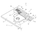
図1は本発明に係る取付構造の第1の実施形態を示す斜視図である。
図2は本発明に係る取付構造の第2の実施形態を示す斜視図である。
図3は本発明に係る取付構造の第3の実施形態を示す斜視図、図4は図3に示す取付構造のアース端子におけるモーメント発生状態を示す分解斜視図である。
図5は本発明に係る取付構造の第4の実施形態のアース端子を示す斜視図、図6は図5に示すアース端子におけるモーメント発生状態を示す分解斜視図である。
図7は本発明に係る取付構造の第5の実施形態を示す分解斜視図、図8は図7に示す取付構造のアース端子の平面図、図9は図8に示すアース端子の左側面図、図10は図8に示すアース端子の右側面図、図11は図8に示すアース端子の底面図、図12は図8に示すアース端子の正面図、図13は図8に示すアース端子の背面図、図14は図8に示すアース端子のA−A線による端面図、図15は電線を引き剥がすときの荷重特性を示すグラフである。
上述の実施形態においては、電線7を車体パネル2から取り外す際に、アース端子3の熱圧着面32と直交する方向に電線7を引き剥がす場合について説明したが、電線7はアース端子3の熱圧着面32と交差する方向に引き剥がせばよく、電線7の引張方向とアース端子3の熱圧着面32とは必ずしも90°で交差する必要はない。
2……車体パネル(被取付部材)
21……パネル本体
22……ボルト挿通孔
23……端子係合孔
25……端子固定爪
3……アース端子(接続端子)
31……端子本体
32……熱圧着面
33……締結部
34……車体取付孔(被取付部材取付孔)
35……車体固定爪
36、37……フランジ
38、39……電線かしめ爪(線状体かしめ爪)
5……ボルト
6……ナット
7……電線(線状体)
7a……被覆部
7b……熱圧着部
L3……非干渉距離
LN……電線配設ライン
Claims (5)
- 被取付部材に接続端子が固定され、この接続端子に線状体が取り付けられた取付構造であって、
前記接続端子は、電線配設ラインの一端に形成されて前記線状体の熱圧着部が熱圧着される熱圧着面と、前記電線配設ラインの他端に形成されて前記線状体の被覆部をかしめる線状体かしめ爪と、前記熱圧着面と前記線状体かしめ爪との間から前記電線配設ラインの脇に延びて前記被取付部材への取付孔が穿設された締結部とを備え、
前記電線配設ラインに沿って延びた縁部には、前記接続端子を補剛するフランジが形成されており、
前記線状体かしめ爪によるかしめ力、及び、前記熱圧着面に対する前記熱圧着部の熱圧着力が、前記取付孔を用いて前記被取付部材に前記接続端子を固定する固定力より弱く設定されていることを特徴とする取付構造。 - 被取付部材に接続端子が固定され、この接続端子に線状体が取り付けられた取付構造であって、
前記接続端子は、電線配設ラインの一端に形成されて前記線状体の熱圧着部が熱圧着される熱圧着面と、前記電線配設ラインの他端に形成されて前記線状体の被覆部をかしめる線状体かしめ爪と、前記熱圧着面から前記電線配設ラインの脇に真横に延びて前記被取付部材への取付孔が穿設された締結部とを備え、
前記電線配設ラインに沿って延びた縁部には、前記接続端子を補剛するフランジが形成されており、
前記線状体かしめ爪によるかしめ力、及び、前記熱圧着面に対する前記熱圧着部の熱圧着力が、前記取付孔を用いて前記被取付部材に前記接続端子を固定する固定力より弱く設定されていることを特徴とする取付構造。 - 被取付部材に接続端子が固定され、この接続端子に線状体が取り付けられた取付構造であって、
前記接続端子は、電線配設ラインの一端に形成されて線状体の熱圧着部が熱圧着される熱圧着面と、前記電線配設ラインの他端に形成されて前記線状体の被覆部をかしめる線状体かしめ爪と、前記熱圧着面と前記線状体かしめ爪との間から前記電線配設ラインの脇に延びて前記被取付部材への取付孔が穿設された締結部とを備え、
前記電線配設ラインに沿って延びた縁部と、前記締結部の前記一端側及び前記他端側の縁部には、前記接続端子を補剛するフランジが形成されており、
前記線状体かしめ爪によるかしめ力、及び、前記熱圧着面に対する前記熱圧着部の熱圧着力が、前記取付孔を用いて前記被取付部材に前記接続端子を固定する固定力より弱く設定されていることを特徴とする取付構造。 - 前記線状体かしめ爪は、一対であり、
これらの線状体かしめ爪は、互いに電線配設方向に所定の非干渉距離だけ離れていることを特徴とする請求項1乃至3のいずれかに記載の取付構造。 - 被取付部材に接続端子が固定され、この接続端子に線状体が取り付けられた取付構造であって、
前記接続端子は、電線配設ラインの一端に形成されて前記線状体の熱圧着部が熱圧着される熱圧着面と、前記電線配設ラインの他端に形成されて前記線状体の被覆部をかしめる第1の線状体かしめ爪と、前記熱圧着面と前記第1の線状体かしめ爪との間から前記電線配設ラインの脇に延びて前記被取付部材への取付孔が穿設された締結部と、前記熱圧着面と前記締結部との間に位置した前記電線配設ラインに形成されて前記被覆部をかしめる第2の線状体かしめ爪とを備え、
前記電線配設ラインに沿って延びた縁部には、前記接続端子を補剛するフランジが形成されており、
前記線状体かしめ爪によるかしめ力、及び、前記熱圧着面に対する前記熱圧着部の熱圧着力が、前記取付孔を用いて前記被取付部材に前記接続端子を固定する固定力より弱く設定されていることを特徴とする取付構造。
Priority Applications (3)
| Application Number | Priority Date | Filing Date | Title |
|---|---|---|---|
| JP2007065018A JP4970093B2 (ja) | 2006-08-01 | 2007-03-14 | 取付構造 |
| DE102007035973.1A DE102007035973B4 (de) | 2006-08-01 | 2007-08-01 | Anbringungsaufbau |
| US11/832,150 US7581966B2 (en) | 2006-08-01 | 2007-08-01 | Mounting structure |
Applications Claiming Priority (3)
| Application Number | Priority Date | Filing Date | Title |
|---|---|---|---|
| JP2006209935 | 2006-08-01 | ||
| JP2006209935 | 2006-08-01 | ||
| JP2007065018A JP4970093B2 (ja) | 2006-08-01 | 2007-03-14 | 取付構造 |
Publications (2)
| Publication Number | Publication Date |
|---|---|
| JP2008060059A JP2008060059A (ja) | 2008-03-13 |
| JP4970093B2 true JP4970093B2 (ja) | 2012-07-04 |
Family
ID=38955078
Family Applications (1)
| Application Number | Title | Priority Date | Filing Date |
|---|---|---|---|
| JP2007065018A Active JP4970093B2 (ja) | 2006-08-01 | 2007-03-14 | 取付構造 |
Country Status (3)
| Country | Link |
|---|---|
| US (1) | US7581966B2 (ja) |
| JP (1) | JP4970093B2 (ja) |
| DE (1) | DE102007035973B4 (ja) |
Cited By (1)
| Publication number | Priority date | Publication date | Assignee | Title |
|---|---|---|---|---|
| WO2015064667A1 (ja) * | 2013-11-01 | 2015-05-07 | 矢崎総業株式会社 | リッツ線用端子 |
Families Citing this family (13)
| Publication number | Priority date | Publication date | Assignee | Title |
|---|---|---|---|---|
| CN102214860A (zh) * | 2010-04-12 | 2011-10-12 | 李胜芝 | 异型接线端子 |
| JP5601259B2 (ja) * | 2011-03-24 | 2014-10-08 | 住友電装株式会社 | 端子金具 |
| JP5772810B2 (ja) * | 2012-12-27 | 2015-09-02 | 住友電装株式会社 | ジョイントコネクタ |
| JP6106517B2 (ja) * | 2013-05-09 | 2017-04-05 | 矢崎総業株式会社 | 丸端子固定構造 |
| JP2015060687A (ja) * | 2013-09-18 | 2015-03-30 | 住友電装株式会社 | アース装置 |
| JP2016048644A (ja) * | 2014-08-28 | 2016-04-07 | 矢崎総業株式会社 | アース接続装置 |
| JP6268605B2 (ja) * | 2014-10-27 | 2018-01-31 | 株式会社オートネットワーク技術研究所 | アース用端子金具 |
| JP6766437B2 (ja) * | 2016-05-10 | 2020-10-14 | 株式会社オートネットワーク技術研究所 | 端子付き電線及び端子 |
| JP6524961B2 (ja) * | 2016-05-13 | 2019-06-05 | 株式会社オートネットワーク技術研究所 | フラットケーブル及び止水ケーブル |
| JP6356376B1 (ja) * | 2017-05-31 | 2018-07-11 | Connect Fusion 合同会社 | 電線の接続構造及び補助端子 |
| JP7074080B2 (ja) * | 2019-01-15 | 2022-05-24 | 住友電装株式会社 | 端子付き電線 |
| CN112072348B (zh) * | 2020-09-10 | 2021-09-28 | 泰兴龙溢端子有限公司 | 一种冷压端子 |
| US20240149810A1 (en) * | 2021-03-10 | 2024-05-09 | Sumitomo Wiring Systems, Ltd. | Electrical junction box |
Family Cites Families (11)
| Publication number | Priority date | Publication date | Assignee | Title |
|---|---|---|---|---|
| JPS6132041A (ja) | 1984-07-24 | 1986-02-14 | Olympus Optical Co Ltd | Ttlオ−トストロボ制御装置 |
| US4583069A (en) * | 1984-09-28 | 1986-04-15 | Molex Incorporated | Crimp fuse link assembly |
| JPH06104021A (ja) * | 1992-09-18 | 1994-04-15 | Yazaki Corp | 圧着端子 |
| JP2927623B2 (ja) | 1992-10-15 | 1999-07-28 | 矢崎総業株式会社 | 電線の接続構造及び接続方法 |
| JP3400657B2 (ja) * | 1996-10-22 | 2003-04-28 | 矢崎総業株式会社 | 熱圧着用端子 |
| JP3671615B2 (ja) * | 1997-08-20 | 2005-07-13 | 住友電装株式会社 | アース端子の電線接続部における防水構造 |
| DE60114684T2 (de) * | 2000-03-21 | 2006-06-01 | Yazaki Corp. | Platten-Klemmen-Anordnung |
| JP3923395B2 (ja) * | 2001-09-26 | 2007-05-30 | 矢崎総業株式会社 | 端子金具 |
| JP2003178824A (ja) * | 2001-12-11 | 2003-06-27 | Auto Network Gijutsu Kenkyusho:Kk | アース端子 |
| JP2004040867A (ja) * | 2002-07-01 | 2004-02-05 | Sumitomo Wiring Syst Ltd | 電線取付金具 |
| US7354283B2 (en) * | 2005-09-29 | 2008-04-08 | Yazaki Corporation | Wire-connecting device |
-
2007
- 2007-03-14 JP JP2007065018A patent/JP4970093B2/ja active Active
- 2007-08-01 US US11/832,150 patent/US7581966B2/en not_active Expired - Fee Related
- 2007-08-01 DE DE102007035973.1A patent/DE102007035973B4/de not_active Expired - Fee Related
Cited By (2)
| Publication number | Priority date | Publication date | Assignee | Title |
|---|---|---|---|---|
| WO2015064667A1 (ja) * | 2013-11-01 | 2015-05-07 | 矢崎総業株式会社 | リッツ線用端子 |
| JP2015111556A (ja) * | 2013-11-01 | 2015-06-18 | 矢崎総業株式会社 | リッツ線用端子 |
Also Published As
| Publication number | Publication date |
|---|---|
| DE102007035973B4 (de) | 2019-04-11 |
| DE102007035973A1 (de) | 2008-02-21 |
| US7581966B2 (en) | 2009-09-01 |
| JP2008060059A (ja) | 2008-03-13 |
| US20080032548A1 (en) | 2008-02-07 |
Similar Documents
| Publication | Publication Date | Title |
|---|---|---|
| JP4970093B2 (ja) | 取付構造 | |
| US7828612B2 (en) | Crimp terminal with two pairs of sheath fastening pieces each pair fastening the sheath in superimposing reverse order | |
| US8337251B2 (en) | Tolerance-compensating current distribution board | |
| JP5140414B2 (ja) | コルゲートクランプ | |
| CN105164857B (zh) | 电压接接触装置 | |
| US8926246B2 (en) | Bolt support structure | |
| JP5581983B2 (ja) | 基板用コネクタ | |
| EP2675019A1 (en) | Ground terminal assembly structure and corresponding method | |
| WO2014156590A1 (ja) | 自動変速機の配線ユニット及びこれに用いられる保持プレート | |
| US9231312B2 (en) | Terminal-wire assembly | |
| US9153883B2 (en) | Terminal | |
| US20070264865A1 (en) | Mounting structure and method for removing linear member | |
| US6670555B2 (en) | Terminal | |
| EP2642601A1 (en) | Connector for high-voltage use | |
| JP4054265B2 (ja) | 圧着端子と電線の接続構造 | |
| JP5703011B2 (ja) | ワイヤハーネスのアース接続構造 | |
| JP4914746B2 (ja) | 電気接続箱のハーネス付設構造 | |
| CN109075306B (zh) | 布线模块 | |
| WO2014156591A1 (ja) | 自動変速機の配線ユニット | |
| JP3910403B2 (ja) | 組み合わせアース端子 | |
| WO2017110789A1 (ja) | ワイヤハーネスの端子接続構造 | |
| JP2010003517A (ja) | 端子金具及び端子金具群 | |
| KR20130060021A (ko) | 접지터미널 | |
| JP2014239606A (ja) | ワイヤハーネス取付部材及びワイヤハーネスの取付構造 | |
| WO2017002581A1 (ja) | 組合せ端子金具 |
Legal Events
| Date | Code | Title | Description |
|---|---|---|---|
| A621 | Written request for application examination |
Free format text: JAPANESE INTERMEDIATE CODE: A621 Effective date: 20100128 |
|
| A977 | Report on retrieval |
Free format text: JAPANESE INTERMEDIATE CODE: A971007 Effective date: 20110928 |
|
| A131 | Notification of reasons for refusal |
Free format text: JAPANESE INTERMEDIATE CODE: A131 Effective date: 20111004 |
|
| TRDD | Decision of grant or rejection written | ||
| A01 | Written decision to grant a patent or to grant a registration (utility model) |
Free format text: JAPANESE INTERMEDIATE CODE: A01 Effective date: 20120321 |
|
| A01 | Written decision to grant a patent or to grant a registration (utility model) |
Free format text: JAPANESE INTERMEDIATE CODE: A01 |
|
| A61 | First payment of annual fees (during grant procedure) |
Free format text: JAPANESE INTERMEDIATE CODE: A61 Effective date: 20120404 |
|
| FPAY | Renewal fee payment (event date is renewal date of database) |
Free format text: PAYMENT UNTIL: 20150413 Year of fee payment: 3 |
|
| R150 | Certificate of patent or registration of utility model |
Ref document number: 4970093 Country of ref document: JP Free format text: JAPANESE INTERMEDIATE CODE: R150 Free format text: JAPANESE INTERMEDIATE CODE: R150 |
|
| R250 | Receipt of annual fees |
Free format text: JAPANESE INTERMEDIATE CODE: R250 |
|
| R250 | Receipt of annual fees |
Free format text: JAPANESE INTERMEDIATE CODE: R250 |
|
| R250 | Receipt of annual fees |
Free format text: JAPANESE INTERMEDIATE CODE: R250 |
|
| R250 | Receipt of annual fees |
Free format text: JAPANESE INTERMEDIATE CODE: R250 |
|
| R250 | Receipt of annual fees |
Free format text: JAPANESE INTERMEDIATE CODE: R250 |