JP4981633B2 - Long covering - Google Patents
Long covering Download PDFInfo
- Publication number
- JP4981633B2 JP4981633B2 JP2007298659A JP2007298659A JP4981633B2 JP 4981633 B2 JP4981633 B2 JP 4981633B2 JP 2007298659 A JP2007298659 A JP 2007298659A JP 2007298659 A JP2007298659 A JP 2007298659A JP 4981633 B2 JP4981633 B2 JP 4981633B2
- Authority
- JP
- Japan
- Prior art keywords
- character
- stamped
- circumferential direction
- covering
- outer peripheral
- Prior art date
- Legal status (The legal status is an assumption and is not a legal conclusion. Google has not performed a legal analysis and makes no representation as to the accuracy of the status listed.)
- Expired - Fee Related
Links
Images



Classifications
-
- B—PERFORMING OPERATIONS; TRANSPORTING
- B29—WORKING OF PLASTICS; WORKING OF SUBSTANCES IN A PLASTIC STATE IN GENERAL
- B29C—SHAPING OR JOINING OF PLASTICS; SHAPING OF MATERIAL IN A PLASTIC STATE, NOT OTHERWISE PROVIDED FOR; AFTER-TREATMENT OF THE SHAPED PRODUCTS, e.g. REPAIRING
- B29C48/00—Extrusion moulding, i.e. expressing the moulding material through a die or nozzle which imparts the desired form; Apparatus therefor
- B29C48/15—Extrusion moulding, i.e. expressing the moulding material through a die or nozzle which imparts the desired form; Apparatus therefor incorporating preformed parts or layers, e.g. extrusion moulding around inserts
- B29C48/154—Coating solid articles, i.e. non-hollow articles
-
- B—PERFORMING OPERATIONS; TRANSPORTING
- B29—WORKING OF PLASTICS; WORKING OF SUBSTANCES IN A PLASTIC STATE IN GENERAL
- B29C—SHAPING OR JOINING OF PLASTICS; SHAPING OF MATERIAL IN A PLASTIC STATE, NOT OTHERWISE PROVIDED FOR; AFTER-TREATMENT OF THE SHAPED PRODUCTS, e.g. REPAIRING
- B29C48/00—Extrusion moulding, i.e. expressing the moulding material through a die or nozzle which imparts the desired form; Apparatus therefor
- B29C48/25—Component parts, details or accessories; Auxiliary operations
- B29C48/30—Extrusion nozzles or dies
- B29C48/32—Extrusion nozzles or dies with annular openings, e.g. for forming tubular articles
- B29C48/34—Cross-head annular extrusion nozzles, i.e. for simultaneously receiving moulding material and the preform to be coated
Landscapes
- Engineering & Computer Science (AREA)
- Mechanical Engineering (AREA)
- Insulated Conductors (AREA)
- Manufacturing & Machinery (AREA)
Description
本発明は、被覆長尺物に関する。特に、架空布設される絶縁電線、ケーブル等の架空被覆長尺物に係り、外周面に周方向に所定の間隔をおいて複数の山部と隣り合う山部に挟まれた複数の谷部が設けられた被覆長尺物に関する。 The present invention relates to a long coated article. In particular, it relates to aerial covering long objects such as insulated wires and cables installed aerial, and has a plurality of troughs sandwiched between a plurality of crests adjacent to a plurality of crests at a predetermined interval in the circumferential direction on the outer peripheral surface. It is related with the provided covering long thing.
一般に、外周に被覆体を設けた絶縁電線、ケーブル等の被覆長尺物の外周面に文字列、模様等を印刷する場合、印刷ロールから被覆体の外周面に印刷インクを転写して文字列、模様等を印刷する印刷ロール方式や、微滴化した印刷インクを被覆体の外周面に直接吹き付けて文字列、模様等を印刷するインクジェット方式や、印刷する文字列、模様等の刻印をロール外周面に凹凸状に加工したエンボスロールを、被覆体の外周面に押し付けて被覆体の外周面に文字列、模様等をエンボス印刷(印字)する(刻印する)エンボスロール方式等により行われている。 In general, when printing a character string, pattern, etc. on the outer peripheral surface of a long covering such as an insulated wire or cable having a covering on the outer periphery, the printing ink is transferred from the printing roll to the outer peripheral surface of the covering. Printing roll system for printing patterns, etc., inkjet system for printing character strings, patterns, etc. by spraying finely printed printing ink directly on the outer peripheral surface of the coated body, and rolls imprints for printed character strings, patterns, etc. The embossing roll processed into irregularities on the outer peripheral surface is pressed against the outer peripheral surface of the covering body, and the character string, pattern, etc. are embossed (printed) (engraved) on the outer peripheral surface of the covering body. Yes.
エンボスロール方式を利用した印刷として、例えば、特許文献1では、社名、商標、マーク、記号、製造年月日、ロットナンバー等の文字、数字、模様からなるエンボス表示を施したラミネート多芯平行電線の製造方法が提案されている。また、特許文献2では、スパイラルヒレ付き絶縁電線を製造する回転ダイスと一体化した印刷ロールを設けることにより外周にエンボス印刷を行うスパイラルヒレ付き絶縁電線のためのエンボス印刷装置が提案されている。また、特許文献3では、印刷ロールを用いて被覆電線の表面に連続模様や文字列を印刷する際、印刷ロールと一体的に配備された電磁石を用いて、印刷中に印刷ロールの制御を行うことができる表面印刷装置が提案されている。 As printing using the embossing roll method, for example, in Patent Document 1, a laminated multi-core parallel wire provided with an embossing display consisting of letters, numbers, and patterns such as company name, trademark, mark, symbol, date of manufacture, and lot number. The manufacturing method of this is proposed. Patent Document 2 proposes an emboss printing apparatus for an insulated wire with spiral fins that performs emboss printing on the outer periphery by providing a printing roll integrated with a rotary die that manufactures insulated wires with spiral fins. Moreover, in patent document 3, when printing a continuous pattern and a character string on the surface of a covered electric wire using a printing roll, the printing roll is controlled during printing using an electromagnet provided integrally with the printing roll. Surface printing devices that can be used have been proposed.
外周面の周方向に所定の間隔をおいて複数の山部と隣り合う山部に挟まれた複数の谷部が設けられた、外周表面が凹凸状になっている絶縁電線等の外周面に文字や模様を印刷する場合、印刷ロール方式では山部の頂点のみにしか印刷インクが付着せず、文字や模様を判別することができなかった。 On the outer peripheral surface of an insulated wire or the like that has a plurality of valleys sandwiched between peaks adjacent to a plurality of peaks with a predetermined interval in the circumferential direction of the outer peripheral surface, etc. When printing characters and patterns, the printing roll method only attaches printing ink to only the tops of the peaks, and the characters and patterns cannot be identified.
また、エンボスロール方式では、隣り合う2つの谷部の最下点間である山幅に文字や模様を印刷していたため、山幅に合わせたサイズの文字や模様しか印刷することができず、狭い山幅を持つ絶縁電線等では文字や模様を容易に判別するように印刷することが難しかった。
その為、従来は、外周面の周方向に所定の間隔をおいて複数の山部と隣り合う山部に挟まれた複数の谷部が設けられた、外周表面が凹凸状になっている絶縁電線等の外周面に文字や模様を印刷する場合、インクジェット方式を用いて、複数の隣り合う山部を有した領域にサイズの大きな文字や模様の印刷を行っていた。
Also, in the embossing roll method, characters and patterns were printed on the mountain width that is between the lowest points of two adjacent valleys, so only characters and patterns of sizes that match the mountain width can be printed, It is difficult to print so that characters and patterns can be easily identified with an insulated wire having a narrow mountain width.
Therefore, conventionally, a plurality of valleys sandwiched between a plurality of ridges adjacent to a plurality of ridges at a predetermined interval in the circumferential direction of the outer peripheral surface are provided, and the outer peripheral surface has an uneven surface. When printing a character or a pattern on the outer peripheral surface of an electric wire or the like, a large-sized character or pattern is printed in an area having a plurality of adjacent peaks using an inkjet method.
また、特許文献4では、外周表面が凹凸状になっている絶縁電線であり、風圧荷重を小さくした、低風圧絶縁電線が開示されている。また、他に、外周表面が凹凸状になっている絶縁電線は、特許文献5や特許文献6などがある。 Patent Document 4 discloses an insulated wire having an uneven outer peripheral surface and a low wind pressure insulated wire with a reduced wind pressure load. In addition, there are Patent Document 5 and Patent Document 6 as insulated wires whose outer peripheral surfaces are uneven.
しかしながら、印刷ロール方式やインクジェット方式により印刷インクを使用した印刷の場合、外周表面が凹凸状になっている絶縁電線、ケーブル等の被覆長尺物の外周面に印刷された文字や模様は表示がかすれたり、滲んで不鮮明となったり、山部の頂点近傍が摩擦により部分的に消失したりするという問題点があった。
また、架空に布設される外周表面が凹凸状になっている絶縁電線、ケーブル等の被覆長尺物の場合、印刷ロール方式やインクジェット方式により印刷された文字や模様は、屋外にて長期間使用されるため、紫外線劣化等により印刷が消失してしまい、文字や模様を判別することができなくなってしまうという問題点もあった。
However, in the case of printing using printing ink by the printing roll method or ink jet method, the characters and patterns printed on the outer peripheral surface of a long coated object such as an insulated wire or cable whose outer peripheral surface is uneven are displayed. There are problems such as fading, blurring and blurring, and the vicinity of the apex of the mountain portion partially disappearing due to friction.
In addition, in the case of long coverings such as insulated wires and cables that have an uneven outer peripheral surface that is installed in the aerial, characters and patterns printed by the printing roll method or inkjet method can be used outdoors for a long period of time. Therefore, there is a problem that printing is lost due to deterioration of ultraviolet rays or the like, and characters and patterns cannot be discriminated.
本発明は、以上のような問題点を解決するためになされたもので、外周面に判別可能なサイズの文字や模様をエンボス印刷するとともに架空布設による文字や模様の判別劣化を低減することが可能な、外周面に、周方向に所定の間隔をおいて複数の山部と隣り合う山部に挟まれた複数の谷部が設けられた絶縁電線、ケーブル等の被覆長尺物を提供することを目的とする。 The present invention has been made in order to solve the above-described problems, and can emboss and print characters and patterns of a size that can be distinguished on the outer peripheral surface, and reduce the deterioration of characters and patterns due to aerial installation. To provide a long covering such as an insulated wire or cable having a plurality of valleys sandwiched between a plurality of crests adjacent to a plurality of crests at a predetermined interval in the circumferential direction on an outer peripheral surface. For the purpose.
上述した従来の問題点を解決すべく下記の発明を提供する。
本発明の第1の態様にかかる被覆長尺物は、被覆体の外周面に周方向に所定の間隔をおいて複数の山部と2個の前記山部に挟まれた複数の谷部が設けられた被覆長尺物であって、1以上の刻印文字からなる刻印文字列が前記被覆体の前記外周面に識別表示され、前記被覆長尺物に識別表示される前記刻印文字は、凸状に刻印されると共に、当該刻印文字の刻印深さが前記山部の高さ以上であり、かつ、周方向の1個の当該刻印文字の文字高さまたは文字幅が少なくとも1個の前記谷部を挟んで周方向に隣り合う2個の前記山部を含む周方向の長さであり、更に、当該刻印文字は少なくとも1個の当該谷部を挟んで周方向に隣り合う2個の当該山部を含む領域に識別表示されていることを特徴とする。
The following invention is provided to solve the above-mentioned conventional problems.
The long covering according to the first aspect of the present invention has a plurality of crests and a plurality of troughs sandwiched between two crests at a predetermined interval in the circumferential direction on the outer peripheral surface of the covering. A long coated article provided, wherein a stamped character string made up of one or more stamped characters is identified and displayed on the outer peripheral surface of the coated body, and the stamped characters identified and displayed on the coated long object are convex. together are stamped on Jo, the engraved depth of the engraved characters is not less than the height of the ridges, and the circumferential direction of one of the engraved character height or character width is one even without least wherein a length in the circumferential direction, including two of the ridges adjacent to the sandwiched therebetween circumferentially valley, further, two said engraved characters adjacent to each other in the circumferential direction across at least one of said valleys It is characterized in that it is identified and displayed in an area including the mountain part.
これにより、外周面に周方向に所定の間隔をおいて複数の山部と隣り合う山部に挟まれた複数の谷部が設けられた絶縁電線、ケーブル等の被覆長尺物の外周面にエンボス印刷された被覆長尺物の周方向の刻印文字の文字高さまたは文字幅のサイズが大きくなり刻印文字列を容易に判別することができる。ここで、刻印文字は、社名、商標、マーク、記号、製造年月日、ロットナンバー等の文字、数字、模様等をエンボス表示した1以上の文字、数字、模様等である。また、被覆長尺物の周方向の刻印文字の文字高さまたは文字幅とは、被覆長尺物の長手方向に刻印文字列が印刷される場合は、刻印文字の文字高さのことであり、被覆長尺物の周方向に刻印文字列が印刷される場合は、刻印文字の文字幅のことである。 Thereby, on the outer peripheral surface of a long covering object such as an insulated wire or a cable provided with a plurality of troughs sandwiched between a plurality of peak portions adjacent to the plurality of peak portions at a predetermined interval in the circumferential direction on the outer peripheral surface. The size of the character height or character width of the stamped character in the circumferential direction of the coated long object embossed is increased, and the stamped character string can be easily identified. Here, the engraved characters are one or more characters, numbers, patterns, etc. embossed with characters such as company names, trademarks, marks, symbols, manufacturing dates, lot numbers, numbers, patterns, and the like. In addition, the character height or character width of the engraved character in the circumferential direction of the coated long object is the character height of the engraved character when the engraved character string is printed in the longitudinal direction of the coated long object. When a stamped character string is printed in the circumferential direction of the long covering material, it is the character width of the stamped character.
また、外周面に、周方向に所定の間隔をおいて複数の山部と隣り合う山部に挟まれた複数の谷部が設けられた絶縁電線、ケーブル等の被覆長尺物において、その外周面にエンボス印刷された刻印文字の凸が明確になり、より鮮明に刻印文字列を判別することができる。また、長期間にわたり、屋外で被覆長尺物が使用されても刻印文字列が消失することが避けられる。即ち、架空布設による刻印文字列の判別劣化を低減させることができる。 In addition, the outer periphery of a covered long object such as an insulated wire or cable provided with a plurality of troughs sandwiched between crests adjacent to a plurality of crests at a predetermined interval in the circumferential direction. The convexity of the stamped character embossed on the surface becomes clear, and the stamped character string can be distinguished more clearly. Further, even if a long covering material is used outdoors for a long period of time, it is possible to avoid the disappearance of the stamped character string. That is, it is possible to reduce the degradation of the stamped character string due to the aerial installation.
ここで、山部の高さとは、周方向の山部の頂点を内接または概ね内接する円の半径と、周方向の谷部の最下点を外接または概ね外接する円の半径との差である。また、刻印文字の刻印深さは、絶縁電線等においては絶縁設計上の耐圧可能な絶縁被覆の厚さまでの範囲である。 Here, the height of the peak is the difference between the radius of the circle inscribed or approximately inscribed at the apex of the peak in the circumferential direction and the radius of the circle that circumscribes or approximately circumscribed the lowest point of the valley in the circumferential direction. It is. In addition, the marking depth of the marking characters is in the range up to the thickness of the insulation coating capable of withstanding voltage in the insulation design for insulated wires and the like.
本発明によれば、外周面に、周方向に所定の間隔をおいて複数の山部と隣り合う山部に挟まれた複数の谷部が設けられた絶縁電線、ケーブル等の被覆長尺物において、その外周面にエンボス印刷された被覆長尺物の周方向の刻印文字の文字高さまたは文字幅のサイズが大きくなり刻印文字列を容易に判別することができる。また、刻印文字の凸が明確になり、より鮮明に刻印文字列を判別することができる。また、刻印文字列により、製造会社、製造年月、電線種類などを判別(識別)することができる。
加えて、本発明によれば、識別表示を付しても低風圧絶縁電線の低風圧性能を保持できる。
According to the present invention, a long covering material such as an insulated wire or a cable provided with a plurality of troughs sandwiched between crests adjacent to a plurality of crests at a predetermined interval in the circumferential direction on the outer peripheral surface. , The size of the character height or character width of the circumferentially imprinted characters embossed and printed on the outer peripheral surface is increased, and the imprinted character string can be easily identified. Further, the convexity of the stamped character becomes clear, and the stamped character string can be discriminated more clearly. Further, the manufacturing company, the manufacturing date, the electric wire type, and the like can be discriminated (identified) by the stamped character string.
In addition, according to the present invention, the low wind pressure performance of the low wind pressure insulated electric wire can be maintained even if the identification display is attached.
また、長期間にわたり、屋外で被覆長尺物が使用されても刻印文字列が消失することが避けられる。即ち、架空布設による刻印文字列の判別劣化を低減させることができる。 Further, even if a long covering material is used outdoors for a long period of time, it is possible to prevent the stamped character string from being lost. That is, it is possible to reduce the degradation of the stamped character string due to the aerial installation.
この発明の一実施形態を、図面を参照しながら説明する。なお、以下に説明する実施形態は説明のためのものであり、本発明の範囲を制限するものではない。従って、当業者であればこれらの各要素もしくは全要素をこれと同等なもので置換した実施形態を採用することが可能であるが、これらの実施形態も本発明の範囲に含まれる。 An embodiment of the present invention will be described with reference to the drawings. In addition, embodiment described below is for description and does not limit the scope of the present invention. Accordingly, those skilled in the art can employ embodiments in which each or all of these elements are replaced by equivalents thereof, and these embodiments are also included in the scope of the present invention.
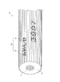
図1は、本発明を適用可能な被覆長尺物の横断面図の一例であり、図2は、本発明を適用可能な被覆長尺物の一部を示す斜視図の一例であり、図3は、エンボス印刷に使用するエンボスロールの概略斜視図の一例であり、図4は、図3のエンボスロールの概略縦断面図及び概略正面図の一例である。なお、図4の(a)は、刻印文字列を凸状にしたときの概略縦断面図であり、図4の(b)は、(a)のA−A線における概略正面図であり、図4の(c)は、刻印文字列を凹状にしたときの概略縦断面図であり、図4の(d)は、(c)のB−B線における概略正面図である。以下では、被覆長尺物として絶縁電線を例に挙げて説明する。 FIG. 1 is an example of a cross-sectional view of a long coated object to which the present invention can be applied, and FIG. 2 is an example of a perspective view showing a part of the long coated object to which the present invention can be applied. 3 is an example of a schematic perspective view of an embossing roll used for emboss printing, and FIG. 4 is an example of a schematic longitudinal sectional view and a schematic front view of the embossing roll of FIG. 4A is a schematic vertical cross-sectional view when the engraved character string is convex, and FIG. 4B is a schematic front view taken along the line AA in FIG. (C) of FIG. 4 is a schematic longitudinal sectional view when the engraved character string is formed into a concave shape, and (d) of FIG. 4 is a schematic front view taken along line BB of (c). Below, an insulated wire is mentioned as an example and it demonstrates as a covering long thing.
図1に示すように、絶縁電線10は、導体11と、導体11の外周に絶縁材料を押出成形して被覆形成された絶縁層である被覆体12とから構成される。被覆体12は、外周面に周方向に所定の間隔をおいて複数の山部13と、隣り合う該山部13に挟まれた複数の谷部14が設けられている。各山部13は丸みのある外凸の曲面を持ち、各谷部14は丸みのある外凹の曲面を持ち、山部13の曲面と谷部14の曲面とは滑らかに連なっている。また、山部13と谷部14とは、絶縁電線10の長手方向に直線状に形成されている。
As shown in FIG. 1, the insulated
また、図2及び図3に示すように、絶縁電線10は、1個または複数の刻印文字31からなる刻印文字列32が被覆体12の外周面にエンボス印刷されている。エンボス印刷は、絶縁電線10の被覆体12が完全に硬化する前に、外凹の曲面である外周面に刻印文字列32を反転した刻印部21(22)を有したロール形状のエンボスロール20を押し付け、絶縁電線10の長手方向への移動による被覆体12とエンボスロール20との間の摩擦によりエンボスロール20を回転させることで、絶縁電線10の長手方向へ印刷が行われる。なお、絶縁電線10の被覆体12の外周面に、複数回エンボス印刷される刻印文字列32の間隔は、エンボスロール20の外周長である。
Further, as shown in FIGS. 2 and 3, the insulated
また、図1、図2、図4(a)及び図4(b)に示すように、絶縁電線10の被覆体12の外周面にエンボス印刷された刻印文字31の文字高さSは、1個の谷部14と該谷部14を挟んで周方向に隣り合う2個の山部13からなる周方向の長さl以上である。また、刻印文字31の刻印深さD1は、山部13の高さh以上である。なお、刻印文字31の刻印深さD1は、絶縁電線10においては絶縁設計上の最小絶縁体(被覆体12)の厚さまでの範囲である。
As shown in FIGS. 1, 2, 4 (a) and 4 (b), the character height S of the stamped
図1に示すように、山部13の高さhは、周方向の山部13の頂点を内接または概ね内接する円15の半径と、周方向の谷部の最下点を外接または概ね外接する円16の半径との差である。また、長さlは、円15の半径と円16の半径との平均を半径とする円17上と被覆体12の外周面とが交差する連続した4点間の距離である。
As shown in FIG. 1, the height h of the
上述したように、文字高さSが長さl以上であり、かつ、刻印文字31の刻印深さD1は山部13の高さh以上である刻印文字31を絶縁電線10の被覆体12の外周面にエンボス印刷することにより、刻印文字31の文字高さSのサイズが大きくなり刻印文字列32を容易に判別することができる。また、刻印文字31の凹凸が明確になり、より鮮明に刻印文字列32を判別することができる。
As described above, the character height S is equal to or longer than the length l, and the stamped
また、図3のエンボスロール20に刻印部21(22)を多段に設け、図2に示すように刻印文字31を多段に印刷することができる。また、エンボスロール20を絶縁電線10の外周に沿う方向に大きくすることにより刻印部21(22)を多段に設け、刻印文字31が多段に印刷することができる。また、エンボスロール20を複数個用意し、それらを並列または/および直列に配置することにより、刻印文字31を多段に印刷することができる。
Further, the marking portion 21 (22) to the
また、エンボスロール20の直径を大きくすることにより円周が長くなるので、刻印文字列を絶縁電線10の長手方向に文字数を多く印刷できる。あるいは、刻印文字または/および刻印文字列を間欠的に印刷することができる。
In addition, since the circumference becomes longer by increasing the diameter of the
また、長期間にわたり、屋外で絶縁電線10が使用されても刻印文字列32が消失することが避けられる。即ち、架空布設による刻印文字列32の判別劣化を低減させることができる。
Moreover, even if the
上述した絶縁電線10のエンボス印刷は、絶縁電線10の長手方向への印刷であったが、絶縁電線10の周方向への印刷であっても良い。そのときは、刻印文字31の文字幅が長さl以上であり、かつ、刻印文字31の刻印深さD1は山部13の高さh以上となるように印刷する。
Although the emboss printing of the
また、上述した絶縁電線10のエンボス印刷は、エンボスロール20を使用して印刷していたが、図5に示すような外凹の曲面である表面に刻印文字列32を反転した刻印部41を有した判子40であっても良い。
Moreover, although the embossing printing of the
また、上述した絶縁電線10のエンボス印刷は、図4(a)及び(b)に示すように刻印文字31を周辺部より凸状に浮かび上がることにより形成している場合と、図4(c)及び(d)に示すように刻印文字31を周辺部より凹状に沈むことにより形成している場とを記載したが、刻印文字31が周辺部より凸状であるものと凹状であるものとが混在していても良い。
Moreover, the emboss printing of the
以上のことは、様々な条件の刻印文字列32をエンボス印刷した絶縁電線10を試作し、実験した結果から判明した。次に、エンボスロール20を使用してエンボス印刷した様々な条件で試作した絶縁電線10を使用して実験した結果を示す。
The above has been found from experimental results obtained by experimentally testing the
(実施例1)
図1に示した外周に凹凸がある絶縁電線にエンボスロールを使用して、絶縁電線にエンボス印刷された刻印文字の刻印深さと文字高さの違いによる、刻印文字の判別可否を示す。また、絶縁電線が低風圧性能を有するとき、低風圧性能を測定した結果もあわせて表1に示す。なお、使用した絶縁電線は低風圧絶縁電線であり、外径が約20mm、山部の高さが0.5mm、山部の間隔が2.1mmである。ここで、山部の間隔とは、1つの谷部を挟んで隣り合う2つの山部の頂点間の距離である。また、文字高さと、谷部を挟んで隣り合う山部の個数とが対応する。
Example 1
The embossing roll is used for the insulated wire which has an unevenness | corrugation in the outer periphery shown in FIG. 1, and the discrimination | determination of the stamped character by the difference in the stamping depth and the character height of the stamping character emboss-printed on the insulated wire is shown. Table 1 also shows the results of measuring the low wind pressure performance when the insulated wire has low wind pressure performance. In addition, the used insulated wire is a low wind pressure insulated wire, and an outer diameter is about 20 mm, the height of a peak part is 0.5 mm, and the space | interval of a peak part is 2.1 mm. Here, the interval between the peaks is the distance between the vertices of two peaks adjacent to each other across one valley. In addition, the character height corresponds to the number of adjacent peak portions across the valley.
刻印文字の判別可否は、絶縁電線の被覆体の外周面にエンボス印刷した刻印文字が、視覚的に鮮明に判別できる場合を判別可(○)とし、視覚的にぎりぎり判別できる場合を判別可限界(△)とし、視覚的に判別できない場合を判別不可(×)とした。 Whether or not the stamped characters can be distinguished is determined to be discriminable (○) when the stamped characters embossed on the outer peripheral surface of the insulated wire sheath can be clearly distinguished, and it is possible to distinguish when the margin can be visually discriminated. (△), and the case where it cannot be visually discriminated is marked as indistinguishable (×).
また、低風圧性能は、絶縁電線を所定の風の中に、エンボス印刷部分を含み、風向きに対して所定の長さの絶縁電線の長手方向を直角に置いた場合の風圧特性であり、エンボス印刷されていない状態の絶縁電線の低風圧特性を100%としたとき、エンボス印刷された状態の絶縁電線の低風圧特性が90%未満(低風圧性能の低下が10%超)であった場合に低風圧性能の低下(×)とし、風圧特性が90%以上であった場合に低風圧性能の保持(○)とした。 The low wind pressure performance is a wind pressure characteristic when an insulated wire is placed in a predetermined wind, including an embossed printed portion, and the longitudinal direction of the insulated wire having a predetermined length with respect to the wind direction is placed at right angles. When the low wind pressure characteristic of the uninsulated insulated wire is 100% and the low wind pressure characteristic of the embossed insulated wire is less than 90% (decrease in low wind pressure performance is more than 10%) When the wind pressure characteristics were 90% or more, the low wind pressure performance was maintained (O).
なお、風圧特性の設定や絶縁電線を敷設する線路設計等によっては、エンボス印刷されていない状態の絶縁電線に比べ60%程度に低風圧性能を保持してれば良い場合もあるので、それらの場合は、別途、絶縁電線の太さ、絶縁電線の外周の凹凸の大きさや数量、形状等や、エンボス印刷の刻印文字数やその大きさ等を適宜変更することによって、低風圧性能をその都度設定してよい。 Depending on the setting of the wind pressure characteristics and the line design for laying insulated wires, it may be necessary to keep the low wind pressure performance to about 60% compared to insulated wires that are not embossed. In this case, low wind pressure performance is set each time by changing the thickness of the insulated wire, the size, quantity, shape, etc. of the irregularities on the outer periphery of the insulated wire, the number of embossed printed characters and the size, etc. You can do it.

表1から判るように、刻印文字の刻印深さが0.5mm以上であり、かつ、谷部を挟んで隣り合う山部の個数が2個以上(即ち、文字高さが3mm以上)であるとき、刻印文字を鮮明に判別することができることがわかった。
また、刻印文字の刻印深さが0.5mm以上であり、かつ、山部の個数が1個(即ち、文字高さが1.5mm)であるときを除いた条件下では、低風圧性能の保持できることがわかった。また、刻印文字の刻印深さが0.5mm以上であり、かつ、山部の個数が1個(即ち、文字高さが1.5mm)であるときに低風圧性能が低下した原因は、文字高さが小さいために、エンボスロールの刻印部以外の外周部により隣接する山部が潰されたためである。
As can be seen from Table 1, the stamping depth of the stamped characters is 0.5 mm or more, and the number of adjacent mountain portions across the valley is two or more (that is, the character height is 3 mm or more). It was found that the engraved characters can be clearly distinguished.
In addition, under the conditions except when the stamping depth of the stamped character is 0.5 mm or more and the number of ridges is one (that is, the character height is 1.5 mm), the low wind pressure performance I found that I could hold it. In addition, when the stamping depth of the stamped character is 0.5 mm or more and the number of ridges is one (that is, the character height is 1.5 mm), the cause of the decrease in the low wind pressure performance is the character This is because the ridges adjacent to each other are crushed by the outer peripheral portion other than the stamped portion of the embossing roll because the height is small.
以上のことから、刻印文字の刻印深さが山部の高さ以上であり、かつ、エンボス印刷される周方向の1個の刻印文字の文字高さが、少なくとも1個の谷部を挟んで周方向に隣り合う2個の山部を含む周方向の長さであり、かつ、刻印文字は少なくとも1個の谷部を挟んで周方向に隣り合う2個の山部を含む領域にエンボス印刷された絶縁電線においては、刻印文字の文字高さのサイズが大きくなり刻印文字列を容易に判別することができるとともに刻印文字の凹凸が明確になり、より鮮明に刻印文字列を判別することができることがわかった。 From the above, the stamping depth of the stamped character is equal to or higher than the height of the mountain portion, and the character height of one stamped character in the circumferential direction to be embossed printed is sandwiching at least one valley. It is the length in the circumferential direction including two crests adjacent in the circumferential direction, and the stamped character is embossed in an area including two crests adjacent in the circumferential direction across at least one trough. In the insulated electric wire, the size of the character height of the engraved character becomes large and the engraved character string can be easily discriminated, and the unevenness of the engraved character becomes clear, and the engraved character string can be discriminated more clearly. I knew it was possible.
(実施例2)
図1に示した外周に凹凸がある絶縁電線にエンボスロールを使用して、絶縁電線の外径、山部の高さ、及び山部の間隔の違いによる、刻印文字の判別可否を示す。また、絶縁電線が低風圧性能を有するとき、低風圧性能を測定した結果もあわせて表2から表5に示す。なお、エンボスロールにより印刷する(刻印する)、刻印文字の刻印深さが山部の高さであり、かつ、刻印文字が1個の谷部を挟んで周方向に隣り合う2個の山部を含む領域にエンボス印刷した。
(Example 2)
The embossing roll is used for the insulated wire having irregularities on the outer periphery shown in FIG. Tables 2 to 5 also show the results of measuring the low wind pressure performance when the insulated wire has low wind pressure performance. In addition, two crests that are printed (embossed) by an embossing roll, the imprinting depth of the imprinted character is the height of the crest, and the imprinted character is adjacent in the circumferential direction across one trough Embossed printing was performed on the area including
表2から表5より判るように、絶縁電線の外径(約10mm、30mm)、山部の高さ(0.2mm、0.3mm、0.6mm、0.9mm)、及び山部の間隔(約0.9mm、1.3mm、2.6mm、3.9mm)が異なっても、刻印文字を鮮明に判別することができることがわかった。また、絶縁電線の外径、山部の高さ、及び山部の間隔が異なっても、低風圧性能を保持できることがわかった。 As can be seen from Table 2 to Table 5, the outer diameter of the insulated wire (about 10 mm, 30 mm), the height of the peak (0.2 mm, 0.3 mm, 0.6 mm, 0.9 mm), and the distance between the peaks It was found that even if (about 0.9 mm, 1.3 mm, 2.6 mm, 3.9 mm) is different, the engraved characters can be clearly distinguished. It was also found that low wind pressure performance can be maintained even when the outer diameter of the insulated wire, the height of the ridges, and the interval between the ridges are different.
以上のことから、刻印文字の刻印深さが山部の高さ以上であり、かつ、エンボス印刷される周方向の1個の刻印文字の文字高さが、少なくとも1個の谷部を挟んで周方向に隣り合う2個の山部を含む周方向の長さであり、かつ、刻印文字は少なくとも1個の谷部を挟んで周方向に隣り合う2個の山部を含む領域にエンボス印刷された絶縁電線においては、刻印文字の文字高さのサイズが大きくなり刻印文字列を容易に判別することができるとともに刻印文字の凹凸が明確になり、より鮮明に刻印文字列を判別することができることがわかった。 From the above, the stamping depth of the stamped character is equal to or higher than the height of the mountain portion, and the character height of one stamped character in the circumferential direction to be embossed printed is sandwiching at least one valley. It is the length in the circumferential direction including two crests adjacent in the circumferential direction, and the stamped character is embossed in an area including two crests adjacent in the circumferential direction across at least one trough. In the insulated electric wire, the size of the character height of the engraved character becomes large and the engraved character string can be easily discriminated, and the unevenness of the engraved character becomes clear, and the engraved character string can be discriminated more clearly. I knew it was possible.
また、本発明の任意の刻印文字に、エンボス印刷とほぼ同時、あるいは、後からカラーインクを塗布又は印刷してよい。 In addition, color ink may be applied or printed on any engraved character of the present invention almost simultaneously with emboss printing or afterwards.
10 絶縁電線
11 導体
12 被覆体
13 山部
14 谷部
20 エンボスロール
21 刻印部
31 刻印文字
32 刻印文字列
DESCRIPTION OF
Claims (1)
1以上の刻印文字からなる刻印文字列が前記被覆体の前記外周面に識別表示され、
前記被覆長尺物に識別表示される前記刻印文字は、凸状に刻印されると共に、当該刻印文字の刻印深さが前記山部の高さ以上であり、かつ、周方向の1個の当該刻印文字の文字高さまたは文字幅が少なくとも1個の前記谷部を挟んで周方向に隣り合う2個の前記山部を含む周方向の長さであり、更に、当該刻印文字は少なくとも1個の当該谷部を挟んで周方向に隣り合う2個の当該山部を含む領域に識別表示されていることを特徴とする被覆長尺物。 A covering long object provided with a plurality of crests and a plurality of troughs sandwiched between two crests at a predetermined interval in the circumferential direction on the outer peripheral surface of the covering,
A stamped character string composed of one or more stamped characters is identified and displayed on the outer peripheral surface of the covering,
The stamped letter recognized displayed on the coating long was, while being inscribed in a convex shape, and the engraved depth of the engraved characters or height of the ridges, and the circumferential direction of one of the even without least a character height or character width of engraved characters are circumferential length comprising one of said valleys two of the crest sandwiched therebetween circumferentially adjacent to, further, the engraved characters at least A long covering material, characterized in that it is identified and displayed in a region including two crests adjacent in the circumferential direction across one trough.
Priority Applications (1)
| Application Number | Priority Date | Filing Date | Title |
|---|---|---|---|
| JP2007298659A JP4981633B2 (en) | 2007-11-16 | 2007-11-16 | Long covering |
Applications Claiming Priority (1)
| Application Number | Priority Date | Filing Date | Title |
|---|---|---|---|
| JP2007298659A JP4981633B2 (en) | 2007-11-16 | 2007-11-16 | Long covering |
Publications (2)
| Publication Number | Publication Date |
|---|---|
| JP2009123630A JP2009123630A (en) | 2009-06-04 |
| JP4981633B2 true JP4981633B2 (en) | 2012-07-25 |
Family
ID=40815548
Family Applications (1)
| Application Number | Title | Priority Date | Filing Date |
|---|---|---|---|
| JP2007298659A Expired - Fee Related JP4981633B2 (en) | 2007-11-16 | 2007-11-16 | Long covering |
Country Status (1)
| Country | Link |
|---|---|
| JP (1) | JP4981633B2 (en) |
Families Citing this family (4)
| Publication number | Priority date | Publication date | Assignee | Title |
|---|---|---|---|---|
| BRPI1011064A2 (en) | 2009-05-21 | 2016-04-05 | Sharp Kk | liquid crystal panel |
| JP5389875B2 (en) * | 2011-09-01 | 2014-01-15 | 北日本電線株式会社 | Low wind piezoelectric wire with fins |
| JP6052359B2 (en) * | 2014-09-11 | 2016-12-27 | 住友電気工業株式会社 | Insulated wire |
| CN106125241A (en) * | 2016-08-30 | 2016-11-16 | 江苏中天科技股份有限公司 | A kind of air-blowing high-strength micro vitta fiber unit |
Family Cites Families (3)
| Publication number | Priority date | Publication date | Assignee | Title |
|---|---|---|---|---|
| JPS5987708A (en) * | 1982-11-11 | 1984-05-21 | 昭和電線電纜株式会社 | Embossing device for cable |
| JPS60102808A (en) * | 1983-11-09 | 1985-06-07 | 日立電線株式会社 | Method of mark for identifying line on surface of cable at laying time |
| JP4383038B2 (en) * | 2002-11-26 | 2009-12-16 | 古河電気工業株式会社 | Low wind pressure resistant snow insulated wire |
-
2007
- 2007-11-16 JP JP2007298659A patent/JP4981633B2/en not_active Expired - Fee Related
Also Published As
| Publication number | Publication date |
|---|---|
| JP2009123630A (en) | 2009-06-04 |
Similar Documents
| Publication | Publication Date | Title |
|---|---|---|
| US9040825B2 (en) | Conductors and metal-covered cable with coded information and method of applying coded information | |
| USRE38345E1 (en) | Armored cable | |
| ES2951277T3 (en) | Printer for printing marking strips | |
| JP2009123630A (en) | Long covering | |
| US10369735B2 (en) | Marking strip | |
| FI92888C (en) | Color coding of data carriers | |
| CA2683332A1 (en) | Metal-clad cable with foraminous coded label | |
| US3229623A (en) | Marking metal sheathed cables | |
| EP0938417A1 (en) | Improvements in and relating to security documents | |
| JP2022505561A5 (en) | ||
| CN203876359U (en) | Gravure plate roller | |
| CN107076950B (en) | Optical fiber cable with printed protective outer surface profile | |
| US11247404B1 (en) | Method and apparatus for applying labels to cable | |
| JP6052359B2 (en) | Insulated wire | |
| JP3636953B2 (en) | Crease member, crease template, crease device and cardboard sheet | |
| CN109383122B (en) | Transfer printing belt | |
| KR100407150B1 (en) | The Marking Roller for the Cable | |
| CN218343097U (en) | Heating substrate for thermal printing head and thermal printing head | |
| ES2992258T3 (en) | Embossing structure for an embossing roll for gluing tissue paper products, a corresponding embossing roll, a corresponding tissue paper product and a method for manufacturing an embossing roll | |
| JP6125550B2 (en) | Printing apparatus and printing method | |
| JP2011246163A (en) | Bundling band | |
| DE102014207271A1 (en) | Conductor wire, cable with such and theft protection system | |
| JP2544729Y2 (en) | Tape roll | |
| JP6581336B2 (en) | Pneumatic tire | |
| US11840103B2 (en) | Tapeless carrier for mechanically fixing tube-shaped objects |
Legal Events
| Date | Code | Title | Description |
|---|---|---|---|
| A977 | Report on retrieval |
Free format text: JAPANESE INTERMEDIATE CODE: A971007 Effective date: 20110425 |
|
| A131 | Notification of reasons for refusal |
Free format text: JAPANESE INTERMEDIATE CODE: A131 Effective date: 20110523 |
|
| A521 | Written amendment |
Free format text: JAPANESE INTERMEDIATE CODE: A523 Effective date: 20110720 |
|
| TRDD | Decision of grant or rejection written | ||
| A01 | Written decision to grant a patent or to grant a registration (utility model) |
Free format text: JAPANESE INTERMEDIATE CODE: A01 Effective date: 20120406 |
|
| A01 | Written decision to grant a patent or to grant a registration (utility model) |
Free format text: JAPANESE INTERMEDIATE CODE: A01 |
|
| A61 | First payment of annual fees (during grant procedure) |
Free format text: JAPANESE INTERMEDIATE CODE: A61 Effective date: 20120420 |
|
| FPAY | Renewal fee payment (event date is renewal date of database) |
Free format text: PAYMENT UNTIL: 20150427 Year of fee payment: 3 |
|
| R150 | Certificate of patent or registration of utility model |
Ref document number: 4981633 Country of ref document: JP Free format text: JAPANESE INTERMEDIATE CODE: R150 Free format text: JAPANESE INTERMEDIATE CODE: R150 |
|
| R250 | Receipt of annual fees |
Free format text: JAPANESE INTERMEDIATE CODE: R250 |
|
| R250 | Receipt of annual fees |
Free format text: JAPANESE INTERMEDIATE CODE: R250 |
|
| S111 | Request for change of ownership or part of ownership |
Free format text: JAPANESE INTERMEDIATE CODE: R313117 |
|
| R350 | Written notification of registration of transfer |
Free format text: JAPANESE INTERMEDIATE CODE: R350 |
|
| R250 | Receipt of annual fees |
Free format text: JAPANESE INTERMEDIATE CODE: R250 |
|
| R250 | Receipt of annual fees |
Free format text: JAPANESE INTERMEDIATE CODE: R250 |
|
| R250 | Receipt of annual fees |
Free format text: JAPANESE INTERMEDIATE CODE: R250 |
|
| LAPS | Cancellation because of no payment of annual fees |