JP4982547B2 - Working fluid test bench adjustment system and apparatus for driving this type of test bench adjustment system - Google Patents
Working fluid test bench adjustment system and apparatus for driving this type of test bench adjustment system Download PDFInfo
- Publication number
- JP4982547B2 JP4982547B2 JP2009246234A JP2009246234A JP4982547B2 JP 4982547 B2 JP4982547 B2 JP 4982547B2 JP 2009246234 A JP2009246234 A JP 2009246234A JP 2009246234 A JP2009246234 A JP 2009246234A JP 4982547 B2 JP4982547 B2 JP 4982547B2
- Authority
- JP
- Japan
- Prior art keywords
- conduit
- heat exchanger
- test bench
- mixing valve
- coolant
- Prior art date
- Legal status (The legal status is an assumption and is not a legal conclusion. Google has not performed a legal analysis and makes no representation as to the accuracy of the status listed.)
- Expired - Fee Related
Links
- 239000012530 fluid Substances 0.000 title description 34
- 238000010438 heat treatment Methods 0.000 claims description 17
- 239000003507 refrigerant Substances 0.000 claims description 14
- 239000002826 coolant Substances 0.000 claims description 10
- 238000004891 communication Methods 0.000 claims description 4
- 230000003750 conditioning effect Effects 0.000 claims description 4
- 238000011144 upstream manufacturing Methods 0.000 claims 1
- 238000001816 cooling Methods 0.000 description 8
- 239000000203 mixture Substances 0.000 description 4
- 230000001143 conditioned effect Effects 0.000 description 3
- 238000004378 air conditioning Methods 0.000 description 2
- 239000000498 cooling water Substances 0.000 description 2
- 230000001934 delay Effects 0.000 description 2
- 238000010586 diagram Methods 0.000 description 2
- 238000002485 combustion reaction Methods 0.000 description 1
- 230000001276 controlling effect Effects 0.000 description 1
- 238000002347 injection Methods 0.000 description 1
- 239000007924 injection Substances 0.000 description 1
- 239000000314 lubricant Substances 0.000 description 1
- 239000010687 lubricating oil Substances 0.000 description 1
- 238000005259 measurement Methods 0.000 description 1
- 230000001105 regulatory effect Effects 0.000 description 1
- 238000004088 simulation Methods 0.000 description 1
- XLYOFNOQVPJJNP-UHFFFAOYSA-N water Substances O XLYOFNOQVPJJNP-UHFFFAOYSA-N 0.000 description 1
Images


Classifications
-
- G—PHYSICS
- G01—MEASURING; TESTING
- G01M—TESTING STATIC OR DYNAMIC BALANCE OF MACHINES OR STRUCTURES; TESTING OF STRUCTURES OR APPARATUS, NOT OTHERWISE PROVIDED FOR
- G01M15/00—Testing of engines
- G01M15/02—Details or accessories of testing apparatus
Landscapes
- Physics & Mathematics (AREA)
- General Physics & Mathematics (AREA)
- Other Air-Conditioning Systems (AREA)
- Testing Of Devices, Machine Parts, Or Other Structures Thereof (AREA)
- Testing Of Engines (AREA)
- Control Of Temperature (AREA)
Description
この発明は、試験台に存在する作業機械の作動流体、特に作業機械の冷却剤用の試験台調整システムに関し、調整(コンディショニング)システムが作動流体を循環させる少なくとも一つのポンプと、作業機械の放出導管から来る作動流体を冷却させる熱交換器並びに作業機械への供給導管に供給された作動流体用の加熱装置と混合弁を含有し、放出導管と供給導管の間の遮断可能な迂回路と、作動流体用の温度経過を設定する制御装置並びにこの種の試験台調整システムを作動する装置を備える。 The present invention relates to a test bench conditioning system for work machine working fluid present on a test bench, particularly a work machine coolant, and at least one pump through which the conditioning system circulates the working fluid; A heat exchanger for cooling the working fluid coming from the conduit as well as a heating device and a mixing valve for the working fluid supplied to the supply conduit to the work machine, and a breakable detour between the discharge conduit and the supply conduit; A control device for setting the temperature course for the working fluid and a device for operating such a test bench adjustment system are provided.
車両内の空気流により強制された冷却は、冷却水或いは例えば潤滑剤のような他の作動流体によって行われて、試験台では水熱交換器と交換される。熱交換器内の追加的流れ抵抗を補償させるために冷却すべき媒体用の循環ポンプが設けられてその媒体の熱入力が同様に考慮されなければならない。冷却器、加熱レジスタ、種々のユニット、測定要素と制御要素を介して作動流体が実際の作動中に生じる温度経過を再生させるように調整(コンディショニング)される。 The cooling forced by the air flow in the vehicle is effected by cooling water or other working fluid, such as a lubricant, and is replaced with a water heat exchanger at the test bench. In order to compensate for the additional flow resistance in the heat exchanger, a circulation pump for the medium to be cooled must be provided and the heat input of that medium must be taken into account as well. Via the cooler, heating register, various units, measurement and control elements, the working fluid is conditioned to regenerate the temperature profile that occurs during actual operation.
通常には、制御回路を介して冷却器及び/又は加熱レジスタを介して案内された作動流体が駆動試験から知られた温度経過を出来るだけ正確に再生させるように設定されて、しかし、それはユニットの応答時間とシステム内の無駄時間に基づいて実行出来ない。 Normally, the working fluid guided via the control circuit via the cooler and / or the heating resistor is set to regenerate the temperature profile known from the drive test as accurately as possible, but it is It cannot be executed based on the response time and dead time in the system.
それ故に、この発明の課題は、作業機械の作動流体の温度経過の最適なシミュレーションが所定経過から最小偏差により可能である試験台調整システムとこの種のシステムを作動する装置を提供することである。 SUMMARY OF THE INVENTION Therefore, an object of the present invention is to provide a test bench adjustment system and an apparatus for operating this kind of system in which an optimum simulation of the temperature course of the working fluid of a work machine is possible with a minimum deviation from a predetermined course. .
この課題を解決するために、調整システムは、混合弁の前で制御弁との連結導管が放出導管に案内され、ポンプの前でこの放出導管に連通することを特徴としている。この連結導管によって、温度制御が三つのそれ自体独立の制御回路に分割されて、加熱作動流体、冷却作動流体とこれらの二つの割合の混合物に別々に応答できる。異なった割合の加熱作動流体と冷却作動流体の混合によって混合された作動流体の所定温度が加熱或いは冷却のみによって可能であるより実質的により迅速に調整され得る。加熱レジスタ或いは冷却器における装置関連遅延がこのアプローチによって回避される。 In order to solve this problem, the regulation system is characterized in that the connecting conduit with the control valve is guided in the discharge conduit before the mixing valve and communicates with this discharge conduit in front of the pump. With this connecting conduit, the temperature control is divided into three independent control circuits that can respond separately to the heated working fluid, the cooled working fluid, and a mixture of these two ratios. The predetermined temperature of the working fluid mixed by mixing different proportions of heated and cooled working fluid can be adjusted substantially more quickly than is possible by heating or cooling alone. Device related delays in the heating register or cooler are avoided by this approach.
この発明の実施例によると、このシステムはさらに、熱交換器の冷媒回路には、迂回導管が冷媒の供給導管からその放出導管まで案内され、混合弁が迂回流の量を調整するように設けられている。この特徴によって冷却回路がより正確に且つ迅速に冷却された作動流体の所望の温度に制御できる。 According to an embodiment of the present invention, the system is further provided in the refrigerant circuit of the heat exchanger such that a bypass conduit is guided from the refrigerant supply conduit to its discharge conduit and a mixing valve regulates the amount of bypass flow. It has been. This feature allows the cooling circuit to be more accurately and quickly controlled to the desired temperature of the cooled working fluid.
この発明の別の実施態様は、作業機械の放出導管と供給導管の間の遮断可能な迂回路の分岐と注入は加熱装置或いは熱交換器に属するシステム成分より近くに配置されている。 In another embodiment of the invention, the breakable bypass branch and injection between the work machine discharge and supply conduits are located closer to the system components belonging to the heating device or heat exchanger.
この課題を解決するために、最初に挙げられた装置は、この発明によると、温度経過が制御装置に貯蔵され、制御装置が熱交換器の迂回導管中の混合弁や加熱装置へ平行な連結導管中の制御弁を制御して、各時点の作動流体用の混合弁には、温度経過による現実の目標温度を備える部分流や現実の目標温度以下に位置する温度を備える部分流が供給され、そして制御装置が作動流体用の混合弁を制御して、両部分流が現実の目標温度で正確に混合される。 In order to solve this problem, according to the present invention, the first mentioned device has a temperature profile stored in the control device, which is connected in parallel to the mixing valve and the heating device in the bypass conduit of the heat exchanger. By controlling the control valve in the conduit, the partial flow with the actual target temperature or the partial flow with the temperature located below the actual target temperature is supplied to the mixing valve for the working fluid at each point of time. And the controller controls the mixing valve for the working fluid so that both partial streams are accurately mixed at the actual target temperature.
この発明は、次に添付図面に基づいて詳細に説明される。 The invention will now be described in detail with reference to the accompanying drawings.
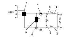
図1は先行技術による従来のシステムを示し、図2はこの発明によるシステムの表示であり、図3は部分流や調整された作動流体の温度経過の線図を示す。 FIG. 1 shows a conventional system according to the prior art, FIG. 2 is a representation of the system according to the invention, and FIG. 3 shows a diagram of the temperature profile of a partial flow or conditioned working fluid.
作業機械に循環する作動流体、特に冷却水、しかも、潤滑油などが放出導管1を介して作業機械から放出され、供給導管2を介して空調後に再び作業機械、例えば内燃機関に供給される。第一装置までの放出導管1或いは供給導管2は代表的にはおよそ5メータである。作動流体の循環のために、調整システムが少なくとも一つのポンプ3を有する。通常には、作業機械の放出導管1から来る作動流体を冷却する熱交換器4及び供給導管2で作業機械へ供給された作動流体用の加熱装置5が設けられている。好都合には、しばしば、直接にポンプ3の前や混合弁6の後にこれら構成部材のそれぞれに直接付近に連通していて、弁7によって遮断可能な迂回路8が放出導管1と供給導管2の間に設けられている。作動流体用の温度経過を与える制御装置が図面には図示されていない。
A working fluid that circulates to the work machine, particularly cooling water, and lubricating oil is discharged from the work machine via the
この発明による作動流体用の調整システムの図2に図示された実施例は、従来のシステムとの基本的差異として連結導管10を有し、この連結導管は混合弁6の前、即ちこの混合弁6の作業機械と反対側で出発し、ポンプ3の前、即ちこのポンプ3と作業機械の間で放出導管1に連通する。連結導管10には、制御弁11が挿入されている。この連結導管10によって、温度制御が三つのそれ自体独立の制御回路に分割され、加熱された作動流体、冷却された作動流体とこれら二つの作動流体の混合物に別々に応答できる。
The embodiment shown in FIG. 2 of the regulating system for working fluid according to the invention has a connecting
好ましくは作業機械の放出導管1と供給導管2の間で遮断可能な迂回路10の分岐と連通が加熱装置5或いは熱交換器4に属するシステム成分よりも作業機械に接近して配置されている。
Preferably, the branching and communication of the
熱交換器4の冷媒回路には、好ましくは、冷媒迂回導管12が冷媒の供給導管13からその放出導管14へ案内され得て、その冷媒迂回導管12には、冷媒の混合弁15が迂回流の量を調整するように設けられて、冷却回路をより正確に且つ迅速に冷却された作動流体(冷却剤)の所望温度に制御できる。
In the refrigerant circuit of the
非常に正確に且つ迅速に与えられた温度経過を実施できるために、好ましくは、空調システムの制御装置には、温度経過が貯蔵され、制御装置が熱交換器4の迂回導管12における可能な混合弁15を作動し、加熱装置5と平行な連結導管10における制御弁11を作動し、温度経過による現実の目標温度S以上を備える部分流Wと現実の目標温度S以下である温度の部分流Kが各時点で作動流体の混合弁6に供給される。さらに、制御装置が作動流体の混合弁6を作動し、両部分流W、Kから全体流が現実の目標温度Sに正確に混合される。
In order to be able to carry out a given temperature course very accurately and quickly, preferably the temperature system is stored in the control unit of the air conditioning system and the control unit can mix in the
図3の線図において明確に認識するように、異なった割合の加熱作動流体Wと冷却作動流体Kのこれら混合物によって本質的に迅速に且つ正確に混合された作動流体の制御装置によって与えられた目標温度Sが加熱或いは冷却単独によって可能であるように設定される。加熱レジスタ5或いは冷却器4における装置関連遅延がこのアプローチによって回避される。
As clearly seen in the diagram of FIG. 3, given by the control device of the working fluid which is essentially rapidly and accurately mixed by these mixtures of different proportions of heated working fluid W and cooling working fluid K. The target temperature S is set so as to be possible by heating or cooling alone. Device related delays in the
1.....放出導管
2.....供給導管
3.....ポンプ
4.....冷却器
5.....加熱レジスタ
6.....混合弁
8.....迂回路
10....連結導管
11....制御弁
12....迂回導管
13....供給導管
14....放出導管
15....混合弁
1. . . . .
Claims (4)
この調整システムは、放出導管(1)、少なくとも一つのポンプ(3)、供給導管(2)、熱交換器(4)、加熱装置(5)、および、迂回路(8)からなり、
放出導管(1)は、作業機械からの冷却剤を受け入れ、かつ、放出導管(1)からの冷却剤を冷却する熱交換器(4)に接続し、
少なくとも一つのポンプ(3)は、熱交換器(4)を通して冷却剤を循環させる放出導管(1)に設けられ、
供給導管(2)は、作業機械に冷却剤を供給するため、熱交換器(4)と作業機械を接続し、
加熱装置(5)は、熱交換器(4)を迂回する迂回連絡導管中に設けられ、この迂回連絡導管は、供給導管(2)に設けられた混合弁(6)を介して供給導管(2)に接続し、
迂回路(8)は、遮断弁(7)を備えるとともに、熱交換器(4)と加熱装置(5)を迂回して放出導管(1)と供給導管(2)を接続する試験台調整システムにおいて、
さらに連結導管(10)が設けられ、この連結導管(10)は、制御弁(11)を備えるとともに、熱交換器(4)と混合弁(6)の間の供給導管(2)と、ポンプ(3)上流における放出導管(1)とを連通することを特徴とする試験台調整システム。 A test bench conditioning system for a work machine of the coolant present in the test stand,
The conditioning system consists of a discharge conduit (1), at least one pump (3), a supply conduit (2), a heat exchanger (4), a heating device (5), and a bypass (8),
The discharge conduit (1) is connected to a heat exchanger (4) that receives the coolant from the work machine and cools the coolant from the discharge conduit (1);
At least one pump (3) is provided in the discharge conduit (1) for circulating the coolant through the heat exchanger (4),
A supply conduit (2) connects the heat exchanger (4) and the work machine to supply coolant to the work machine,
The heating device (5) is provided in a bypass communication conduit that bypasses the heat exchanger (4), which bypass communication conduit is connected via a mixing valve (6) provided in the supply conduit (2) ( 2)
The bypass circuit (8) includes a shut-off valve (7) and a test bench adjusting system that bypasses the heat exchanger (4) and the heating device (5) and connects the discharge conduit (1) and the supply conduit (2). In
Furthermore, a connecting conduit (10) is provided, which comprises a control valve (11), a supply conduit (2) between the heat exchanger (4) and the mixing valve (6), and a pump. (3) test stand adjustment system, characterized in that communicating the discharge conduit (1) upstream.
制御装置は、熱交換器(4)の冷媒迂回導管(12)における冷媒の混合弁(15)、連結導管(10)の制御弁(11)、及び供給導管(2)の混合弁(6)を制御し、
現実の目標温度(S)以上の温度を備える迂回連絡導管の部分流(W)と現実の目標温度(S)以下である温度を備える供給導管の部分流(K)が、各時点で冷却剤の混合弁(6)に供給され、そして、制御装置に貯蔵された温度経過に基づく目標温度(S)に、全体の流れが両部分流(W、K)から正確に混合されるように、冷却剤の混合弁(6)が制御されることを特徴とする請求項2に記載の試験台調整システムを作動する装置。 A control device is provided, in which the temperature profile of the coolant is stored,
The control device comprises a refrigerant mixing valve (15) in the refrigerant bypass conduit (12) of the heat exchanger (4), a control valve (11) of the connecting conduit (10), and a mixing valve (6) of the supply conduit (2). Control
Partial stream of bypass contact conduit comprising a target temperature (S) above the temperature of the real (W) and the real part flow of the feed conduit with a target temperature (S) or less is temperature (K) is the coolant at each time point So that the entire flow is accurately mixed from both partial flows (W, K) to a target temperature (S) based on the temperature course supplied to the mixing valve (6) and stored in the controller Apparatus for operating a test bench adjustment system according to claim 2 , characterized in that the coolant mixing valve (6) is controlled .
Applications Claiming Priority (2)
| Application Number | Priority Date | Filing Date | Title |
|---|---|---|---|
| AT0062108U AT10460U3 (en) | 2008-10-30 | 2008-10-30 | TEST LEVEL CONDITIONING SYSTEM FOR A WORKFLUID, AND DEVICE FOR OPERATING SUCH A TEST BENCH CONDITIONING SYSTEM |
| ATGM621/2008 | 2008-10-30 |
Publications (2)
| Publication Number | Publication Date |
|---|---|
| JP2010107510A JP2010107510A (en) | 2010-05-13 |
| JP4982547B2 true JP4982547B2 (en) | 2012-07-25 |
Family
ID=40240496
Family Applications (1)
| Application Number | Title | Priority Date | Filing Date |
|---|---|---|---|
| JP2009246234A Expired - Fee Related JP4982547B2 (en) | 2008-10-30 | 2009-10-27 | Working fluid test bench adjustment system and apparatus for driving this type of test bench adjustment system |
Country Status (4)
| Country | Link |
|---|---|
| US (1) | US8117905B2 (en) |
| JP (1) | JP4982547B2 (en) |
| AT (1) | AT10460U3 (en) |
| DE (1) | DE102009049209B4 (en) |
Families Citing this family (9)
| Publication number | Priority date | Publication date | Assignee | Title |
|---|---|---|---|---|
| CN101968401B (en) * | 2009-07-28 | 2012-09-26 | 北汽福田汽车股份有限公司 | Cooling fluid temperature control system for testing engine performance |
| CN103134687B (en) * | 2013-01-30 | 2016-03-16 | 奇瑞汽车股份有限公司 | Air-conditioning system analog loading device in engine rig test |
| DE102016123985A1 (en) | 2015-12-16 | 2017-06-22 | FEV Europe GmbH | Method for influencing oil level fluctuations |
| AT519004B1 (en) * | 2016-11-30 | 2018-03-15 | Avl List Gmbh | Method and device for controlling a conditioning system |
| AT522447B1 (en) * | 2019-04-23 | 2020-11-15 | Christof Systems Gmbh | Device and method for conditioning a medium |
| AT522634B1 (en) * | 2019-05-31 | 2024-08-15 | Kristl Seibt & Co Engineers Ges M B H | Method and a vehicle test bench for testing a vehicle |
| AT524116B1 (en) * | 2020-10-06 | 2022-03-15 | Avl List Gmbh | Conditioning system for a test stand |
| AT524781B1 (en) * | 2021-06-22 | 2022-09-15 | Avl List Gmbh | Conditioning device for a test stand |
| US12516724B2 (en) * | 2024-04-04 | 2026-01-06 | General Electric Company | Systems and methods for heating a gearbox prior to fan rotation |
Family Cites Families (15)
| Publication number | Priority date | Publication date | Assignee | Title |
|---|---|---|---|---|
| US2188172A (en) * | 1937-01-06 | 1940-01-23 | Gen Electric | Heat transfer system |
| JPS5935609A (en) | 1982-08-20 | 1984-02-27 | Nippon Steel Chem Co Ltd | Detection of molten iron |
| JPS5935609U (en) * | 1982-08-30 | 1984-03-06 | トヨタ自動車株式会社 | Engine oil temperature control device |
| JP3015829B2 (en) * | 1992-10-02 | 2000-03-06 | 株式会社小野測器 | Engine lubricating oil temperature control device |
| ES2120174T3 (en) | 1994-01-11 | 1998-10-16 | Abbott Lab | APPARATUS AND PROCEDURE FOR THERMAL CYCLING OF DOSAGES OF NUCLEIC ACIDS. |
| IT1291270B1 (en) | 1997-02-10 | 1998-12-30 | Angelantoni Ind Spa | SYSTEM FOR FAST COOLING OF ENGINES IN TEST BENCHES AND RELATED DEVICE |
| US6427640B1 (en) * | 2000-10-11 | 2002-08-06 | Ford Global Tech., Inc. | System and method for heating vehicle fluids |
| JP3942836B2 (en) * | 2001-03-09 | 2007-07-11 | ジヤトコ株式会社 | Hydraulic oil cooling device for automatic transmission for vehicle |
| FR2832187B1 (en) * | 2001-11-13 | 2005-08-05 | Valeo Thermique Moteur Sa | THERMAL ENERGY MANAGEMENT SYSTEM DEVELOPED BY A MOTOR VEHICLE THERMAL MOTOR |
| US6678628B2 (en) * | 2002-01-14 | 2004-01-13 | William J. Ryan | Apparatus and methods for monitoring and testing coolant recirculation systems |
| FR2852678B1 (en) * | 2003-03-21 | 2005-07-15 | Valeo Thermique Moteur Sa | LOW TEMPERATURE COOLING SYSTEM OF EQUIPMENT, IN PARTICULAR A MOTOR VEHICLE EQUIPMENT, AND RELATED HEAT EXCHANGERS |
| JP4111332B2 (en) * | 2003-11-07 | 2008-07-02 | 三機工業株式会社 | Engine cooling water circulation system for testing |
| JP2008128809A (en) * | 2006-11-21 | 2008-06-05 | Sanki Eng Co Ltd | Temperature adjustment device for testing |
| FR2909713B1 (en) | 2006-12-12 | 2009-02-27 | Renault Sas | SYSTEM FOR CONTROLLING THE TEMPERATURE OF AN ENGINE ON A TEST BENCH. |
| US7748262B2 (en) * | 2008-10-09 | 2010-07-06 | Toyota Motor Engineering & Manufacturing North America, Inc. | Coolant flow measurement devices and methods of measuring coolant flow |
-
2008
- 2008-10-30 AT AT0062108U patent/AT10460U3/en not_active IP Right Cessation
-
2009
- 2009-10-13 DE DE102009049209.7A patent/DE102009049209B4/en not_active Expired - Fee Related
- 2009-10-27 JP JP2009246234A patent/JP4982547B2/en not_active Expired - Fee Related
- 2009-10-28 US US12/588,813 patent/US8117905B2/en not_active Expired - Fee Related
Also Published As
| Publication number | Publication date |
|---|---|
| AT10460U3 (en) | 2009-09-15 |
| DE102009049209B4 (en) | 2020-06-04 |
| US20100116040A1 (en) | 2010-05-13 |
| DE102009049209A1 (en) | 2010-07-08 |
| AT10460U2 (en) | 2009-03-15 |
| JP2010107510A (en) | 2010-05-13 |
| US8117905B2 (en) | 2012-02-21 |
Similar Documents
| Publication | Publication Date | Title |
|---|---|---|
| JP4982547B2 (en) | Working fluid test bench adjustment system and apparatus for driving this type of test bench adjustment system | |
| JP7248378B2 (en) | Method for operating ship cooling system | |
| JP4572131B2 (en) | Engine variable separation cooling structure and engine cooling system | |
| US8757110B2 (en) | Coolant circuit | |
| CN101809262B (en) | Arrangement for cooling of oil in a gearbox for a vehicle | |
| CN100585141C (en) | Cooling water circuit system | |
| JP2003293772A (en) | Cooling system of automobile engine having indirect air supply cooling | |
| JP2012504205A (en) | Cooling circuit for temperature control independent of other consumption parts of the engine | |
| CN112839836B (en) | Cooling system, vehicle comprising such a cooling system and method of cooling a battery | |
| JP2014081251A (en) | Water cooled type transmission oil heat exchanger test system | |
| US7929305B1 (en) | Power electronics cooling system with flow orifice control | |
| EP3194810B1 (en) | Transmission heat exchange system | |
| JP4947292B2 (en) | Fuel temperature control device | |
| JP2005090508A (en) | Temperature control method for internal combustion engine and cooling system for internal combustion engine | |
| KR20180049018A (en) | Cooling device for electric power unit in vehicle | |
| KR20200003910A (en) | Cooling system for combustion engine and WHR system | |
| CN204961050U (en) | Engine cooling system and vehicle | |
| JP2005140654A (en) | Engine cooling water circulation system for test | |
| JP6652719B2 (en) | Temperature control device | |
| JP2016118115A (en) | Cooling device of rotary piston engine | |
| JP2001271644A (en) | Engine oil temperature adjusting method and oil temperature adjusting device | |
| KR20110071720A (en) | Fan motor control system of construction machinery | |
| JP2001228924A (en) | Method of changing temperature control fluid temperature at high speed in heat exchanger and circulator provided with the device | |
| JPH10197009A (en) | Room temperature control method and apparatus by bypass control | |
| JP3079542U (en) | Temperature control mechanism for chiller |
Legal Events
| Date | Code | Title | Description |
|---|---|---|---|
| RD04 | Notification of resignation of power of attorney |
Free format text: JAPANESE INTERMEDIATE CODE: A7424 Effective date: 20100604 |
|
| A131 | Notification of reasons for refusal |
Free format text: JAPANESE INTERMEDIATE CODE: A131 Effective date: 20110906 |
|
| A601 | Written request for extension of time |
Free format text: JAPANESE INTERMEDIATE CODE: A601 Effective date: 20111205 |
|
| A602 | Written permission of extension of time |
Free format text: JAPANESE INTERMEDIATE CODE: A602 Effective date: 20111208 |
|
| A601 | Written request for extension of time |
Free format text: JAPANESE INTERMEDIATE CODE: A601 Effective date: 20120105 |
|
| A602 | Written permission of extension of time |
Free format text: JAPANESE INTERMEDIATE CODE: A602 Effective date: 20120111 |
|
| A601 | Written request for extension of time |
Free format text: JAPANESE INTERMEDIATE CODE: A601 Effective date: 20120203 |
|
| A602 | Written permission of extension of time |
Free format text: JAPANESE INTERMEDIATE CODE: A602 Effective date: 20120208 |
|
| A521 | Request for written amendment filed |
Free format text: JAPANESE INTERMEDIATE CODE: A523 Effective date: 20120209 |
|
| TRDD | Decision of grant or rejection written | ||
| A01 | Written decision to grant a patent or to grant a registration (utility model) |
Free format text: JAPANESE INTERMEDIATE CODE: A01 Effective date: 20120327 |
|
| A01 | Written decision to grant a patent or to grant a registration (utility model) |
Free format text: JAPANESE INTERMEDIATE CODE: A01 |
|
| A61 | First payment of annual fees (during grant procedure) |
Free format text: JAPANESE INTERMEDIATE CODE: A61 Effective date: 20120423 |
|
| FPAY | Renewal fee payment (event date is renewal date of database) |
Free format text: PAYMENT UNTIL: 20150427 Year of fee payment: 3 |
|
| R150 | Certificate of patent or registration of utility model |
Ref document number: 4982547 Country of ref document: JP Free format text: JAPANESE INTERMEDIATE CODE: R150 Free format text: JAPANESE INTERMEDIATE CODE: R150 |
|
| R250 | Receipt of annual fees |
Free format text: JAPANESE INTERMEDIATE CODE: R250 |
|
| R250 | Receipt of annual fees |
Free format text: JAPANESE INTERMEDIATE CODE: R250 |
|
| R250 | Receipt of annual fees |
Free format text: JAPANESE INTERMEDIATE CODE: R250 |
|
| R250 | Receipt of annual fees |
Free format text: JAPANESE INTERMEDIATE CODE: R250 |
|
| R250 | Receipt of annual fees |
Free format text: JAPANESE INTERMEDIATE CODE: R250 |
|
| R250 | Receipt of annual fees |
Free format text: JAPANESE INTERMEDIATE CODE: R250 |
|
| R250 | Receipt of annual fees |
Free format text: JAPANESE INTERMEDIATE CODE: R250 |
|
| R250 | Receipt of annual fees |
Free format text: JAPANESE INTERMEDIATE CODE: R250 |
|
| LAPS | Cancellation because of no payment of annual fees |