JP4982884B2 - Solar simulator - Google Patents
Solar simulator Download PDFInfo
- Publication number
- JP4982884B2 JP4982884B2 JP2006309113A JP2006309113A JP4982884B2 JP 4982884 B2 JP4982884 B2 JP 4982884B2 JP 2006309113 A JP2006309113 A JP 2006309113A JP 2006309113 A JP2006309113 A JP 2006309113A JP 4982884 B2 JP4982884 B2 JP 4982884B2
- Authority
- JP
- Japan
- Prior art keywords
- integrator
- collimation lens
- angle
- light
- focal length
- Prior art date
- Legal status (The legal status is an assumption and is not a legal conclusion. Google has not performed a legal analysis and makes no representation as to the accuracy of the status listed.)
- Active
Links
Images



Classifications
-
- F—MECHANICAL ENGINEERING; LIGHTING; HEATING; WEAPONS; BLASTING
- F21—LIGHTING
- F21S—NON-PORTABLE LIGHTING DEVICES; SYSTEMS THEREOF; VEHICLE LIGHTING DEVICES SPECIALLY ADAPTED FOR VEHICLE EXTERIORS
- F21S8/00—Lighting devices intended for fixed installation
- F21S8/006—Solar simulators, e.g. for testing photovoltaic panels
-
- G—PHYSICS
- G02—OPTICS
- G02B—OPTICAL ELEMENTS, SYSTEMS OR APPARATUS
- G02B27/00—Optical systems or apparatus not provided for by any of the groups G02B1/00 - G02B26/00, G02B30/00
- G02B27/09—Beam shaping, e.g. changing the cross-sectional area, not otherwise provided for
- G02B27/0938—Using specific optical elements
- G02B27/095—Refractive optical elements
- G02B27/0955—Lenses
Landscapes
- Physics & Mathematics (AREA)
- General Physics & Mathematics (AREA)
- Optics & Photonics (AREA)
- Life Sciences & Earth Sciences (AREA)
- Sustainable Development (AREA)
- Engineering & Computer Science (AREA)
- General Engineering & Computer Science (AREA)
- Non-Portable Lighting Devices Or Systems Thereof (AREA)
- Securing Globes, Refractors, Reflectors Or The Like (AREA)
Description
本発明は、ソーラパネル等の測定に用いられるソーラシミュレータに関する。 The present invention relates to a solar simulator used for measuring solar panels and the like.
図3は、従来技術に係るソーラシミュレータにおいて、出射光の平行度角を上げるために取られてきた標準的な光学構造を示す図である。
同図に示すように、通常、入射角θ1と出射角θ2を等しく設計した均一照射用インテグレ−タ4を用いて、不図示の光源からの光を光軸の近くに集めた後、コリメーションレンズ5により収束させ、高平行度出射光を得ている。
ここで、コリメーションレンズ5から出射された光の平行度角φは、φ≒atan(r/f)で近似できる。ただし、rはインテグレータ4の外接円半径、fはコリメ−ションレンズ5の焦点距離である。
従来、このような構造においては、出射光束の平行度角を上げる(φを小さくする)ために、コリメーションレンズ5の焦点距離fを大きく取る方法が取られてきた。
As shown in the figure, after collimating the light from a light source (not shown) using a uniform irradiation integrator 4 in which the incident angle θ1 and the outgoing angle θ2 are designed to be equal, the collimation lens is usually collected. 5 to obtain a highly parallel light.
Here, the parallelism angle φ of the light emitted from the collimation lens 5 can be approximated by φ≈atan (r / f). Here, r is a circumscribed circle radius of the integrator 4, and f is a focal length of the collimation lens 5.
Conventionally, in such a structure, a method of increasing the focal length f of the collimation lens 5 has been taken in order to increase the parallelism angle of the emitted light beam (decrease φ).
しかしながら、図3に示すような光学構造においては、インテグレータ4の出射角θ2を固定したまま、図4に示すように、平行度角φを上げるためにコリメ−ションレンズ5の焦点距離fを大きくしていくと、インテグレータ4とコリメーションレンズ5間の距離も大きくなるため、インテグレータ4からの出射光はコリメーションレンズ5の外まで大きく拡がる。つまり、インテグレータ4から出射した光の大部分がコリメーションレンズ5外に放散されてしまう。そのため、光エネルギーの損失が大きく、また、コリメーションレンズ5から得られる平行光の照度も小さくなるという問題が生じていた。
本発明の目的は、出射光の高平行度化と出射光の高照度化の問題を同時に解決すると共に、出射光の均一度を上げることを可能にしたソーラシミュレータを提供することにある。
However, in the optical structure as shown in FIG. 3, the focal length f of the collimation lens 5 is increased in order to increase the parallelism angle φ as shown in FIG. 4 while the output angle θ2 of the integrator 4 is fixed. As a result, the distance between the integrator 4 and the collimation lens 5 also increases, so that the light emitted from the integrator 4 greatly spreads outside the collimation lens 5. That is, most of the light emitted from the integrator 4 is diffused out of the collimation lens 5. For this reason, there has been a problem that the loss of light energy is large and the illuminance of parallel light obtained from the collimation lens 5 is also small.
An object of the present invention is to provide a solar simulator that can simultaneously solve the problems of increasing the parallelism of the emitted light and increasing the illuminance of the emitted light, and can increase the uniformity of the emitted light.
本発明は、上記の課題を解決するために、下記の手段を採用した。
光源から放射された光をインテグレータに入射し、該インテグレータから出射された光をコリメーションレンズに入射し、該コリメーションレンズから平行光を出射させるソーラシミュレータにおいて、
前記インテグレータの外接円半径をr、前記平行光の平行度角をφ、前記コリメーションレンズの焦点距離をf=r/tanφとするとき、前記平行度角φが2.5°未満でかつ焦点距離fが320mm以上となるように前記焦点距離fを選択するとともに、前記インテグレータは、一辺が5mm以下の9本以上の微小インテグレータの集合体で構成され、かつ、前記インテグレータの外接円半径rが10.6mm以下であり、前記インテグレータから出射される光の出射角をθ、前記コリメーションレンズの直径をD、前記インテグレータから見た前記コリメーションレンズの見込み角度θX=2×atan(D/2f)とするとき、前記出射角θを前記見込み角度θXより小さくしたことを特徴とするソーラシミュレータである。
The present invention employs the following means in order to solve the above problems.
In a solar simulator that enters light emitted from a light source into an integrator, enters light emitted from the integrator into a collimation lens, and emits parallel light from the collimation lens.
When the circumscribed circle radius of the integrator is r, the parallelism angle of the parallel light is φ, and the focal length of the collimation lens is f = r / tanφ, the parallelism angle φ is less than 2.5 ° and the focal length The focal length f is selected so that f is 320 mm or more, and the integrator is composed of an assembly of nine or more micro integrators whose sides are 5 mm or less, and the circumscribed circle radius r of the integrator is 10 0.6 mm or less, the emission angle of light emitted from the integrator is θ, the diameter of the collimation lens is D, and the expected angle of the collimation lens viewed from the integrator is θX = 2 × atan (D / 2f). In this case, the solar simulator is characterized in that the emission angle θ is smaller than the expected angle θX.
請求項1に記載の発明によれば、照射面において、高平行度化された高照度光が得られる。
請求項2に記載の発明によれば、照射面において、高均一化された光が得られる。
According to the first aspect of the present invention, high illuminance light with high parallelism can be obtained on the irradiated surface.
According to the second aspect of the present invention, highly uniform light can be obtained on the irradiated surface.
本発明の一実施形態を図1ないし図4を用いて説明する。
図1は、本実施形態の発明に係るソーラシミュレータの構成を示す図である。
同図に示すように、例えば、300WのXe(キセノン)ランプ1から出射された光は、楕円鏡2によって反射され、AM(エアマス)フィルター3を介して小出射角の微小インテグレータの集合体からなるインテグレータ4に入射される。インテグレータ4から出射された光は長焦点距離を有するコリメーションレンズ5に入射され、高平行度光として出射される。出射された高平行光はソーラパネル等の照射面6に高照度で照射される。
An embodiment of the present invention will be described with reference to FIGS.
FIG. 1 is a diagram showing a configuration of a solar simulator according to the invention of this embodiment.
As shown in the figure, for example, light emitted from a 300 W Xe (xenon) lamp 1 is reflected by an elliptical mirror 2 and passes through an AM (air mass) filter 3 from a collection of small integrators having a small emission angle. Is incident on the integrator 4. The light emitted from the integrator 4 is incident on a collimation lens 5 having a long focal length, and is emitted as high parallel light. The emitted highly parallel light is irradiated to the irradiation surface 6 such as a solar panel with high illuminance.
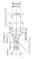
図2は、図1に示したソーラシミュレータにおいて、出射光の平行度角を上げるために取られた光学構造を示す図である。
同図において、不図示の光源から放射された光はインテグレータ4に入射され、インテグレータ4から出射された光はコリメーションレンズ5に入射され、コリメーションレンズ5から平行光が出射される。
ここで、インテグレータ4の外接円半径をr、平行光の平行度角をφ、コリメーションレンズ5の焦点距離をf、インテグレータ4とコリメーションレンズ5間の距離をL、インテグレータ4の入射角をθ1、インテグレータ4の出射角をθ2、コリメーションレンズ5の直径をD、インテグレータ4から見たコリメーションレンズ5の見込み角度をθXとする。
FIG. 2 is a diagram showing an optical structure taken to increase the parallelism angle of outgoing light in the solar simulator shown in FIG.
In the figure, light emitted from a light source (not shown) enters the integrator 4, light emitted from the integrator 4 enters the collimation lens 5, and parallel light is emitted from the collimation lens 5.
Here, the circumscribed circle radius of the integrator 4 is r, the parallelism angle of parallel light is φ, the focal length of the collimation lens 5 is f, the distance between the integrator 4 and the collimation lens 5 is L, the incident angle of the integrator 4 is θ1, Assume that the output angle of the integrator 4 is θ2, the diameter of the collimation lens 5 is D, and the expected angle of the collimation lens 5 viewed from the integrator 4 is θX.
通常、インテグレータ4は、正方形断面の微小インテグレータの集合体からなり、例えば、5mm角の正方形の微小インテグレータの3×3=9本の集合体で構成される。集合体の外形をできるだけ外接円に近づけるためには、各微小インテグレータの断面を正方形以外の多角形、例えば、正6角形で構成するとよい。 Usually, the integrator 4 is composed of an assembly of micro integrators having a square cross section, and is composed of, for example, 3 × 3 = 9 assemblies of 5 mm square micro integrators. In order to make the outer shape of the aggregate as close as possible to the circumscribed circle, it is preferable that the cross section of each micro-integrator be configured by a polygon other than a square, for example, a regular hexagon.
インテグレータ4から出射された光を、焦点距離fのコリメーションレンズ5で収束させる場合、インテグレータ4の外接円の半径rが無限に0に近い場合、インテグレータ4とコリメーションレンズ5間の距離を焦点距離fに等しく取れば、コリメーションレンズ5からの出射光は、球面収差・色収差等を無視すれば、完全な平行光となる。 When the light emitted from the integrator 4 is converged by the collimation lens 5 having the focal length f, when the radius r of the circumscribed circle of the integrator 4 is infinitely close to 0, the distance between the integrator 4 and the collimation lens 5 is determined as the focal length f. Is equal, the emitted light from the collimation lens 5 becomes completely parallel light if spherical aberration, chromatic aberration, etc. are ignored.
しかし、実際のインテグレータ4は、上述のごとく、微小インテグレータの集合体で構成されるため、その外接円半径rは有限の大きさを持つため、その円周上の光(微小インテグレータ個々の光)が、コリメーションレンズ5通過後に光軸となす角度が誤差となって、完全な平行光とはならない。
つまり、コリメーションレンズ5の出射光の平行度角φは、コリメーションレンズ5中心からインテグレータ4を見たときの外接円半径rの見込み角度で求められ、次式で与えられる。
φ=atan(r/L)≒atan(r/f)
ここで、φが小さいとき、L≒fとなる関係を用いた。
However, as described above, the actual integrator 4 is composed of a collection of minute integrators, and therefore the circumscribed circle radius r has a finite size, so that the light on the circumference (light of each minute integrator). However, the angle formed with the optical axis after passing through the collimation lens 5 becomes an error, and the light is not completely parallel.
That is, the parallelism angle φ of the light emitted from the collimation lens 5 is obtained by the expected angle of the circumscribed circle radius r when the integrator 4 is viewed from the center of the collimation lens 5 and is given by the following equation.
φ = atan (r / L) ≈atan (r / f)
Here, when φ is small, a relationship of L≈f is used.
例えば、インテグレータ4の外接円半径r=10.6mm、コリメーションレンズ5の焦点距離f=200mmのとき、平行度角φ=3.04°であり、インテグレータ4の外接円半径r=10.6mm、コリメーションレンズ5の焦点距離f=320mmのとき、平行度角φ=1.90°であった。つまり、コリメーションレンズ5の焦点距離fを200mmから320mmに増加させることにより、実測平行度角φを3.0°から1.9°に改善することができた。このことから、高平行度光を得るためには、コリメーションレンズ5の長焦点化が有効であることが分かる。 For example, when the circumscribed circle radius r of the integrator 4 is 10.6 mm and the focal length f of the collimation lens 5 is 200 mm, the parallelism angle φ is 3.04 °, and the circumscribed circle radius r of the integrator 4 is 10.6 mm. When the focal length f of the collimation lens 5 was 320 mm, the parallelism angle φ was 1.90 °. That is, by increasing the focal length f of the collimation lens 5 from 200 mm to 320 mm, the measured parallelism angle φ can be improved from 3.0 ° to 1.9 °. From this, it can be seen that increasing the focal length of the collimation lens 5 is effective for obtaining highly parallel light.
下記に示す表は、図2〜図4に示す光学構造において、インテグレータ4の出射角θ2、インテグレータ4から見たコリメーションレンズ5の見込み角度をθX、及びコリメーションレンズ5の焦点距離fを変化させたときの、コリメーションレンズ5から出射される光の平行度角、及び照射面6における照度を示すものである。なお、見込み角度θXは、
θX=2×atan(D/2f)で示され、インテグレータ4の入射角θ1はいずれも27°である。
対応図 出射角 見込み角度 焦点距離 平行度角 照度(mW/cm2)
図3 27° 35° 200mm 3.04° 100
図3 27° 30° 250mm 2.43° 67
図4 27° 23° 320mm 1.90° 39
図2 17° 20° 320mm 1.90° 97
The table shown below changes the output angle θ2 of the integrator 4, the expected angle of the collimation lens 5 viewed from the integrator 4, and the focal length f of the collimation lens 5 in the optical structure shown in FIGS. The parallelism angle of the light emitted from the collimation lens 5 and the illuminance on the irradiation surface 6 are shown. The expected angle θX is
θX = 2 × atan (D / 2f), and the incident angle θ1 of the integrator 4 is 27 °.
Corresponding figure Output angle Expected angle Focal length Parallelism angle Illuminance (mW / cm 2 )
Fig. 3 27 ° 35 ° 200mm 3.04 ° 100
Fig. 3 27 ° 30 ° 250mm 2.43 ° 67
Fig. 4 27 ° 23 ° 320mm 1.90 ° 39
Fig. 2 17 ° 20 ° 320mm 1.90 ° 97
上表に示すように、図3及び図4に示す従来の光学構造においては、インテグレータ4の出射角θ2を27°と入射角θ1と等しく固定した場合、焦点距離fが200mm、250mm、320mmと増加させるにつれて、平行度角は3.04°、2.43°、1.90°と改善されるが、照度は100mW/cm2、67mW/cm2、39mW/cm2と減少することが分かる。このように、出射角θ2が27°と大きいと、比較的短焦点のコリメーションレンズ5でないと、照度は100mW/cm2という、所望の高照度を得ることができないということが分かる。
即ち、図4に示す光学構造においては、平行度角が1.90°という高平行度を得るためにコリメーションレンズ5の焦点距離fを320mmと大きくすれば、照度が39mW/cm2と低照度になってしまい、逆に、図3に示す光学構造において、照度を100mW/cm2に維持するためにコリメーションレンズ5の焦点距離fを200mmと小さくすれば、平行度角は3.04°に低下してしまう。
As shown in the above table, in the conventional optical structure shown in FIGS. 3 and 4, when the exit angle θ2 of the integrator 4 is fixed equal to 27 ° and the incident angle θ1, the focal length f is 200 mm, 250 mm, and 320 mm. as increasing parallelism angle 3.04 °, 2.43 °, but is improved as 1.90 °, the illuminance is seen to decrease with 100mW / cm 2, 67mW / cm 2, 39mW / cm 2 . Thus, it can be seen that when the emission angle θ2 is as large as 27 °, the illuminance cannot be as high as 100 mW / cm 2 unless the collimation lens 5 has a relatively short focal point.
That is, in the optical structure shown in FIG. 4, when the focal length f of the collimation lens 5 is increased to 320 mm in order to obtain a high parallelism with a parallelism angle of 1.90 °, the illuminance is as low as 39 mW / cm 2. On the contrary, in the optical structure shown in FIG. 3, if the focal length f of the collimation lens 5 is reduced to 200 mm in order to maintain the illuminance at 100 mW / cm 2 , the parallelism angle becomes 3.04 °. It will decline.
これに対して、上記の問題を解決するために、図2に示す本発明の光学構造においては、インテグレータ4の出射角θ2を、インテグレータ4中心から見たコリメーションレンズ5の見込み角度θXより小さくなるように構成する。このように構成することにより、1.90°という高平行度を得るためにコリメーションレンズ5の焦点距離fを320mmと大きくしても、照度は97mW/cm2となり、図3に示した光学構造における最大照度100mW/cm2とほぼ同水準の照度が得られる。 On the other hand, in order to solve the above problem, in the optical structure of the present invention shown in FIG. 2, the output angle θ2 of the integrator 4 is smaller than the expected angle θX of the collimation lens 5 viewed from the center of the integrator 4. Configure as follows. With this configuration, even when the focal length f of the collimation lens 5 is increased to 320 mm in order to obtain a high parallelism of 1.90 °, the illuminance is 97 mW / cm 2 , and the optical structure shown in FIG. The maximum illuminance at 100 mW / cm 2 is obtained.
ソーラシミュレータ5に要求される他の特性は、照射面6における照度の高均一化である。高均一性を得るためには、例えば、直径が5mm以下である複数の微小インテグレータの集合体であって、この集合体の外接円半径rが10.6mmのインテグレータ4を用いることによって実現することができる。
コリメーションレンズ5の焦点距離320mm、照射面6における有効照射面積を60mm角としたときの、インテグレータ4の細分化の効果を9本と25本の集合本数について実測した結果、3×3(9本組)のインテグレータ4を用いて照射面6における均一度は±4.5%、5×5(25本組)のインテグレータ4を用いて照射面6における均一度は±1.5%であった。この実測結果に示すように、インテグレータ4を9本から25本に細分化することにより、照度の均一度が3倍改善された。
Another characteristic required for the solar simulator 5 is to make the illuminance on the irradiation surface 6 highly uniform. In order to obtain high uniformity, for example, it is realized by using an integrator 4 having a plurality of minute integrators having a diameter of 5 mm or less and having a circumscribed circle radius r of 10.6 mm. Can do.
When the focal length of the collimation lens 5 is 320 mm and the effective irradiation area on the irradiation surface 6 is 60 mm square, the subdivision effect of the integrator 4 is measured for 9 and 25 sets, and 3 × 3 (9) Uniformity on the irradiated surface 6 using the integrator 4 of the set) was ± 4.5%, and uniformity on the irradiated surface 6 using the 5 × 5 (25-piece set) integrator 4 was ± 1.5%. . As shown in the actual measurement results, the uniformity of illuminance was improved by a factor of 3 by subdividing the integrator 4 from 9 to 25.
1 Xe(キセノン)ランプ
2 楕円鏡
3 AM(エアマス)フィルター
4 インテグレータ
5 コリメーションレンズ
6 照射面
1 Xe (xenon) lamp 2 elliptical mirror 3 AM (air mass) filter 4 integrator 5 collimation lens 6 irradiation surface
Claims (1)
前記インテグレータの外接円半径をr、前記平行光の平行度角をφ、前記コリメーションレンズの焦点距離をf=r/tanφとするとき、前記平行度角φが2.5°未満でかつ焦点距離fが320mm以上となるように前記焦点距離fを選択するとともに、前記インテグレータは、一辺が5mm以下の9本以上の微小インテグレータの集合体で構成され、かつ、前記インテグレータの外接円半径rが10.6mm以下であり、前記インテグレータから出射される光の出射角をθ、前記コリメーションレンズの直径をD、前記インテグレータから見た前記コリメーションレンズの見込み角度θX=2×atan(D/2f)とするとき、前記出射角θを前記見込み角度θXより小さくしたことを特徴とするソーラシミュレータ。 In a solar simulator that enters light emitted from a light source into an integrator, enters light emitted from the integrator into a collimation lens, and emits parallel light from the collimation lens.
When the circumscribed circle radius of the integrator is r, the parallelism angle of the parallel light is φ, and the focal length of the collimation lens is f = r / tanφ, the parallelism angle φ is less than 2.5 ° and the focal length The focal length f is selected so that f is 320 mm or more, and the integrator is composed of an assembly of nine or more micro integrators whose sides are 5 mm or less, and the circumscribed circle radius r of the integrator is 10 0.6 mm or less, the emission angle of light emitted from the integrator is θ, the diameter of the collimation lens is D, and the expected angle of the collimation lens viewed from the integrator is θX = 2 × atan (D / 2f). The solar simulator is characterized in that the emission angle θ is smaller than the expected angle θX.
Priority Applications (3)
| Application Number | Priority Date | Filing Date | Title |
|---|---|---|---|
| JP2006309113A JP4982884B2 (en) | 2006-11-15 | 2006-11-15 | Solar simulator |
| PCT/JP2007/071573 WO2008059733A1 (en) | 2006-11-15 | 2007-11-06 | Solar simulator |
| US12/513,301 US8016439B2 (en) | 2006-11-15 | 2007-11-06 | Solar simulator |
Applications Claiming Priority (1)
| Application Number | Priority Date | Filing Date | Title |
|---|---|---|---|
| JP2006309113A JP4982884B2 (en) | 2006-11-15 | 2006-11-15 | Solar simulator |
Publications (2)
| Publication Number | Publication Date |
|---|---|
| JP2008123951A JP2008123951A (en) | 2008-05-29 |
| JP4982884B2 true JP4982884B2 (en) | 2012-07-25 |
Family
ID=39401542
Family Applications (1)
| Application Number | Title | Priority Date | Filing Date |
|---|---|---|---|
| JP2006309113A Active JP4982884B2 (en) | 2006-11-15 | 2006-11-15 | Solar simulator |
Country Status (3)
| Country | Link |
|---|---|
| US (1) | US8016439B2 (en) |
| JP (1) | JP4982884B2 (en) |
| WO (1) | WO2008059733A1 (en) |
Families Citing this family (16)
| Publication number | Priority date | Publication date | Assignee | Title |
|---|---|---|---|---|
| US8646925B2 (en) * | 2010-03-16 | 2014-02-11 | Yamashita Denso Corporation | Solar simulator |
| CN102338323A (en) * | 2010-07-21 | 2012-02-01 | 上海太阳能工程技术研究中心有限公司 | Steady state solar simulator |
| TWI440794B (en) | 2010-09-27 | 2014-06-11 | Ind Tech Res Inst | Solar light simulator |
| JP2013062093A (en) * | 2011-09-13 | 2013-04-04 | Sharp Corp | Pseudo sunlight irradiation device |
| JP6089603B2 (en) * | 2012-11-06 | 2017-03-08 | 岩崎電気株式会社 | Pseudo-sunlight irradiation device |
| CN103091846B (en) * | 2012-12-26 | 2015-04-22 | 中国科学院长春光学精密机械与物理研究所 | Solar simulation device capable of distinguishing photosphere and corona |
| US9410669B2 (en) | 2013-04-10 | 2016-08-09 | The Boeing Company | Multi-lamp solar simulator |
| JPWO2014188746A1 (en) * | 2013-05-20 | 2017-02-23 | 山下電装株式会社 | Solar simulator |
| US9243776B1 (en) | 2013-08-05 | 2016-01-26 | The Boeing Company | Solar simulator and method for solar simulation |
| CN104198383B (en) * | 2014-07-02 | 2017-04-26 | 北京卫星环境工程研究所 | Multi-light-path near-ultraviolet simulator |
| CN104749089A (en) * | 2015-02-06 | 2015-07-01 | 北京环境特性研究所 | Solar simulator adopting heat-sink-free collimating mirror |
| CN105807430A (en) * | 2016-03-17 | 2016-07-27 | 邓泳安 | Parallel discrete light beam emitting system with efficient heat dissipation function |
| CN107966132B (en) * | 2017-11-27 | 2020-07-14 | 上海卫星装备研究所 | Device and method for measuring included angle between central optical axis of solar simulator and central axis of tank body |
| CN111536461B (en) * | 2020-05-12 | 2022-02-11 | 长春理工大学 | Design method of irradiation attenuator of xenon lamp light source solar simulator |
| US11356056B1 (en) | 2020-12-23 | 2022-06-07 | Industrial Technology Research Institute | Photovoltaic mobile lab |
| CN115199967B (en) * | 2022-07-15 | 2024-01-12 | 北京环境特性研究所 | Irradiation distance adjustable solar simulator system |
Family Cites Families (14)
| Publication number | Priority date | Publication date | Assignee | Title |
|---|---|---|---|---|
| JPH0231475B2 (en) * | 1981-10-02 | 1990-07-13 | Hatsuko Kk | JINKOKOGENSOCHI |
| US4641227A (en) * | 1984-11-29 | 1987-02-03 | Wacom Co., Ltd. | Solar simulator |
| JPH0398792U (en) * | 1990-01-23 | 1991-10-15 | ||
| US5217285A (en) * | 1991-03-15 | 1993-06-08 | The United States Of America As Represented By United States Department Of Energy | Apparatus for synthesis of a solar spectrum |
| JP2878944B2 (en) * | 1993-05-19 | 1999-04-05 | 三菱電機株式会社 | Light source device and projection display device |
| JP3600076B2 (en) | 1999-08-04 | 2004-12-08 | 三洋電機株式会社 | Lighting optical system |
| JP2002116501A (en) | 2000-10-10 | 2002-04-19 | Ricoh Co Ltd | Illuminator |
| JP5036102B2 (en) | 2000-10-10 | 2012-09-26 | 株式会社リコー | Lighting device |
| US6866404B2 (en) * | 2001-04-23 | 2005-03-15 | Ricoh Company, Ltd. | Illumination apparatus and a liquid crystal projector using the illumination apparatus |
| JP3937885B2 (en) * | 2002-03-22 | 2007-06-27 | セイコーエプソン株式会社 | Device manufacturing method and device, electro-optical device manufacturing method, electro-optical device, and electronic apparatus |
| JP2004245912A (en) * | 2003-02-12 | 2004-09-02 | Ushio Inc | Light irradiation device |
| JP3098792U (en) * | 2003-06-25 | 2004-03-11 | 山下電装株式会社 | Simulated sunlight irradiation device |
| US7839503B2 (en) * | 2008-07-16 | 2010-11-23 | The Boeing Company | Method and system for a solar simulator |
| JP5283037B2 (en) * | 2009-04-25 | 2013-09-04 | 独立行政法人産業技術総合研究所 | Illumination device and illumination method capable of obtaining high uniform illuminance |
-
2006
- 2006-11-15 JP JP2006309113A patent/JP4982884B2/en active Active
-
2007
- 2007-11-06 WO PCT/JP2007/071573 patent/WO2008059733A1/en not_active Ceased
- 2007-11-06 US US12/513,301 patent/US8016439B2/en active Active
Also Published As
| Publication number | Publication date |
|---|---|
| WO2008059733A1 (en) | 2008-05-22 |
| US8016439B2 (en) | 2011-09-13 |
| JP2008123951A (en) | 2008-05-29 |
| US20100027236A1 (en) | 2010-02-04 |
Similar Documents
| Publication | Publication Date | Title |
|---|---|---|
| US8016439B2 (en) | Solar simulator | |
| CN203930191U (en) | Light source module and projector equipment | |
| JP2015501508A (en) | Light source system and laser light source | |
| US20210208492A1 (en) | Light source device and projection apparatus | |
| JP2015088410A (en) | LED lighting device | |
| JP2007311085A (en) | Simulated solar irradiation device | |
| WO2012002219A1 (en) | Irradiation device | |
| JP5497481B2 (en) | Simulated solar irradiation device | |
| US9625726B2 (en) | Lens array-based illumination for wafer inspection | |
| JP2012094247A (en) | Solar simulator | |
| CN104154495B (en) | Mixed type optics integrator component and its optical system | |
| CN112345481A (en) | Optical system for multi-channel infrared detector | |
| CN103941381A (en) | Collector for weak light in three-dimensional space | |
| CN207880734U (en) | Laser lighting unit and vehicle | |
| WO2012093508A1 (en) | Simulated solar radiation device | |
| CN107831142B (en) | Light scattering confocal excitation collection system | |
| CN114280801B (en) | Uniform illumination system based on free-form surface and its design method | |
| CN111258163A (en) | Light source device, light path structure design method and projection system | |
| CN102734664B (en) | Light-gathering type light source simulator | |
| JP5013415B2 (en) | Light source device and simulated sunlight irradiation device | |
| EP2589857A1 (en) | Light source apparatus and pseudo-sunlight irradiating apparatus provided with same | |
| JP2011222581A (en) | Condenser structure | |
| JP2012094248A (en) | Solar simulator equipped with optical fiber flux light guide member and optical fiber lens | |
| CN104198383B (en) | Multi-light-path near-ultraviolet simulator | |
| JPH0498214A (en) | Laser light irradiation device |
Legal Events
| Date | Code | Title | Description |
|---|---|---|---|
| A621 | Written request for application examination |
Free format text: JAPANESE INTERMEDIATE CODE: A621 Effective date: 20090212 |
|
| A131 | Notification of reasons for refusal |
Free format text: JAPANESE INTERMEDIATE CODE: A131 Effective date: 20110726 |
|
| A521 | Request for written amendment filed |
Free format text: JAPANESE INTERMEDIATE CODE: A523 Effective date: 20110926 |
|
| TRDD | Decision of grant or rejection written | ||
| A01 | Written decision to grant a patent or to grant a registration (utility model) |
Free format text: JAPANESE INTERMEDIATE CODE: A01 Effective date: 20120403 |
|
| A01 | Written decision to grant a patent or to grant a registration (utility model) |
Free format text: JAPANESE INTERMEDIATE CODE: A01 |
|
| A61 | First payment of annual fees (during grant procedure) |
Free format text: JAPANESE INTERMEDIATE CODE: A61 Effective date: 20120406 |
|
| R150 | Certificate of patent or registration of utility model |
Free format text: JAPANESE INTERMEDIATE CODE: R150 Ref document number: 4982884 Country of ref document: JP |
|
| FPAY | Renewal fee payment (event date is renewal date of database) |
Free format text: PAYMENT UNTIL: 20150511 Year of fee payment: 3 |
|
| S533 | Written request for registration of change of name |
Free format text: JAPANESE INTERMEDIATE CODE: R313533 |
|
| R350 | Written notification of registration of transfer |
Free format text: JAPANESE INTERMEDIATE CODE: R350 |
|
| R250 | Receipt of annual fees |
Free format text: JAPANESE INTERMEDIATE CODE: R250 |
|
| R250 | Receipt of annual fees |
Free format text: JAPANESE INTERMEDIATE CODE: R250 |
|
| R250 | Receipt of annual fees |
Free format text: JAPANESE INTERMEDIATE CODE: R250 |
|
| R250 | Receipt of annual fees |
Free format text: JAPANESE INTERMEDIATE CODE: R250 |
|
| R250 | Receipt of annual fees |
Free format text: JAPANESE INTERMEDIATE CODE: R250 |
|
| R250 | Receipt of annual fees |
Free format text: JAPANESE INTERMEDIATE CODE: R250 |
|
| R250 | Receipt of annual fees |
Free format text: JAPANESE INTERMEDIATE CODE: R250 |
|
| R250 | Receipt of annual fees |
Free format text: JAPANESE INTERMEDIATE CODE: R250 |
|
| R250 | Receipt of annual fees |
Free format text: JAPANESE INTERMEDIATE CODE: R250 |
|
| R250 | Receipt of annual fees |
Free format text: JAPANESE INTERMEDIATE CODE: R250 |
|
| R250 | Receipt of annual fees |
Free format text: JAPANESE INTERMEDIATE CODE: R250 |
|
| R250 | Receipt of annual fees |
Free format text: JAPANESE INTERMEDIATE CODE: R250 |