JP4984450B2 - Winding battery manufacturing method - Google Patents
Winding battery manufacturing method Download PDFInfo
- Publication number
- JP4984450B2 JP4984450B2 JP2005208494A JP2005208494A JP4984450B2 JP 4984450 B2 JP4984450 B2 JP 4984450B2 JP 2005208494 A JP2005208494 A JP 2005208494A JP 2005208494 A JP2005208494 A JP 2005208494A JP 4984450 B2 JP4984450 B2 JP 4984450B2
- Authority
- JP
- Japan
- Prior art keywords
- electrode plate
- winding
- positive electrode
- negative electrode
- wound
- Prior art date
- Legal status (The legal status is an assumption and is not a legal conclusion. Google has not performed a legal analysis and makes no representation as to the accuracy of the status listed.)
- Expired - Fee Related
Links
Images




Classifications
-
- Y—GENERAL TAGGING OF NEW TECHNOLOGICAL DEVELOPMENTS; GENERAL TAGGING OF CROSS-SECTIONAL TECHNOLOGIES SPANNING OVER SEVERAL SECTIONS OF THE IPC; TECHNICAL SUBJECTS COVERED BY FORMER USPC CROSS-REFERENCE ART COLLECTIONS [XRACs] AND DIGESTS
- Y02—TECHNOLOGIES OR APPLICATIONS FOR MITIGATION OR ADAPTATION AGAINST CLIMATE CHANGE
- Y02E—REDUCTION OF GREENHOUSE GAS [GHG] EMISSIONS, RELATED TO ENERGY GENERATION, TRANSMISSION OR DISTRIBUTION
- Y02E60/00—Enabling technologies; Technologies with a potential or indirect contribution to GHG emissions mitigation
- Y02E60/10—Energy storage using batteries
-
- Y—GENERAL TAGGING OF NEW TECHNOLOGICAL DEVELOPMENTS; GENERAL TAGGING OF CROSS-SECTIONAL TECHNOLOGIES SPANNING OVER SEVERAL SECTIONS OF THE IPC; TECHNICAL SUBJECTS COVERED BY FORMER USPC CROSS-REFERENCE ART COLLECTIONS [XRACs] AND DIGESTS
- Y02—TECHNOLOGIES OR APPLICATIONS FOR MITIGATION OR ADAPTATION AGAINST CLIMATE CHANGE
- Y02P—CLIMATE CHANGE MITIGATION TECHNOLOGIES IN THE PRODUCTION OR PROCESSING OF GOODS
- Y02P70/00—Climate change mitigation technologies in the production process for final industrial or consumer products
- Y02P70/50—Manufacturing or production processes characterised by the final manufactured product
Landscapes
- Secondary Cells (AREA)
- Battery Electrode And Active Subsutance (AREA)
Description
本発明は,正極板と負極板とをそれぞれセパレータで絶縁しつつ捲回してなる捲回型の電池の製造方法に関する。さらに詳細には,角形ケース等に封入されて使用される扁平型の捲回型電池の製造方法に関するものである。 The present invention relates to a method for manufacturing a wound-type batteries made by winding with insulating separators respectively a positive electrode plate and the negative electrode plate. More particularly, a method for manufacturing a wound-type batteries flat type used are enclosed in square case or the like.
従来より,正極板と負極板とがセパレータを挟んで捲回された電極体を有する電池が使用されている。このような捲回型の電池では,電極体の巻き終わり端部の箇所ではわずかに外形に段差ができる。もし,段差部分に集中的に力が加わった場合には,その段差位置の内部に局所的に大きい圧力が加わるおそれがある。そのため,この巻き終わり端部が適切な位置に来るようにすることが必要である。 Conventionally, a battery having an electrode body in which a positive electrode plate and a negative electrode plate are wound around a separator has been used. In such a wound battery, there is a slight step in the outer shape at the end of the winding end of the electrode body. If a force is applied intensively to the stepped portion, a large pressure may be locally applied to the inside of the stepped position. Therefore, it is necessary to ensure that the end of the winding is in an appropriate position.
ここで,捲回型電池の製造方法の1つとして,略円筒型に捲回した電極積層体を直径方向に押しつぶすことにより,扁平型の電極体を形成する方法がある。この製造方法では,巻き終わり端部をほぼ所望の位置に配置させることができる。例えば特許文献1には,ケースと電極体との間に加圧板を設けて,圧力が集中しないようにした電池が開示されている。この文献に記載の電池では,加圧板による加圧部と電極体側部のR部との間に巻き終わり端部が配置されている。あるいは,特許文献2には,電極体の端部を電極体側面の湾曲部において絶縁テープや接着剤によって固定した電池が開示されている。この文献に記載の電池では,電極体側部のR部に巻き終わり端部が配置されている。
Here, as one of the methods for manufacturing a wound battery, there is a method of forming a flat electrode body by crushing an electrode stack wound in a substantially cylindrical shape in the diameter direction. In this manufacturing method, the winding end end can be arranged at a substantially desired position. For example,
これに対し,捲回時のテンションを一定にして,扁平な巻き芯を軸に初めから扁平に捲回することによる電極体の製造方法がある。一般に電池の正極板や負極板は,金属箔等にそれぞれの活物質を塗工して形成され,その長さは電池容量等の特性によって決定されている。従って,このような電池の電極体は,所定の長さの電極板を所定のテンションをかけつつ扁平に捲回することにより製造される。
しかしながら,前記した扁平な巻き芯によって捲回される電池では,同じ長さの電極板を巻いて製造した電極体であっても,その巻き終わり端部は必ずしも同じ場所に来るとは限らないという問題点があった。電極板は剛体ではないため,同一の製造条件によって製造しても微妙な差が出てくることが避けられないのである。 However, in the battery wound by the flat winding core described above, even if the electrode body is manufactured by winding the electrode plate of the same length, the winding end is not always at the same place. There was a problem. Since the electrode plate is not a rigid body, it is inevitable that subtle differences will occur even if it is manufactured under the same manufacturing conditions.
このため,巻き終わり端部による段差が電極体の捲回平面部に来てしまうと,例えば事故等の原因により部分的に大きな力が加わった場合には,電流集中によるデンドライトが発生するおそれがあった。特にポール側突等の悪条件では,この段差部分からセパレータに亀裂が生じ,短絡するおそれがあるという問題点があった。そのため,巻き終わり端部を確実に両側のR部に配置させたいという要望があった。 For this reason, if a step due to the end of the winding comes to the winding flat part of the electrode body, for example, if a large force is applied partially due to an accident or the like, dendrite due to current concentration may occur. there were. In particular, under bad conditions such as pole side collision, there is a problem that the separator may crack from this stepped portion and may cause a short circuit. For this reason, there has been a demand to securely arrange the winding end portions at the R portions on both sides.
本発明は,前記した従来の捲回型電池の製造方法が有する問題点を解決するためになされたものである。すなわちその課題とするところは,扁平な巻き芯によって扁平に巻かれた電極体を有する捲回型電池であっても,電池特性等に影響を与えることなく,巻き終わり端部を所望の位置に配置させることができる捲回型電池の製造方法を提供することにある。 The present invention has been made to solve the problems method for manufacturing a wound-type batteries of the prior described above has. In other words, the problem is that even with a wound battery having an electrode body that is flatly wound by a flat core, the end of the winding end is brought to a desired position without affecting the battery characteristics. it is to provide a method for manufacturing a wound-type batteries that can be placed.
この課題の解決を目的としてなされた本発明の捲回型電池の製造方法は,正極板と負極板との少なくとも一方に,活物質が塗工されていない未塗工領域を,電極捲回体の周長の2分の1以上の長さにわたって設けておき,正極板と負極板とをセパレータで絶縁しつつ捲回し,正極板または負極板の未塗工領域の少なくとも一部が電極捲回体の外周の所望の領域上に来たときに,その極板の未塗工領域内でかつ所望の領域上の位置を切断することにより,その極板の切断後の巻き終わり端を所望の領域内に配置する捲回型電池の製造方法である。 In order to solve this problem, a method for manufacturing a wound battery according to the present invention includes an electrode winding body in which an uncoated region where no active material is coated is provided on at least one of a positive electrode plate and a negative electrode plate. The positive electrode plate and the negative electrode plate are wound while being insulated by a separator, and at least a part of the uncoated region of the positive electrode plate or the negative electrode plate is wound around the electrode. When it comes to the desired area on the outer periphery of the body, the end of the wound plate after cutting the electrode plate is cut in the desired area by cutting the position in the uncoated area of the electrode plate and on the desired area. It is a manufacturing method of the winding type battery arrange | positioned in an area | region.
本発明の製造方法によれば,正極板と負極板との少なくとも一方に,活物質が塗工されていない未塗工領域が,電極捲回体の周長の2分の1以上の長さにわたって設けられる。さらに,この正極板と負極板とをセパレータで絶縁しつつ捲回し,正極板または負極板の未塗工領域の少なくとも一部が電極捲回体の外周の所望の領域上に来たときに,その極板の未塗工領域内でかつ所望の領域上の位置を切断する。これにより,その極板の切断後の巻き終わり端は,所望の領域内に配置される。 According to the manufacturing method of the present invention, the uncoated region where the active material is not applied to at least one of the positive electrode plate and the negative electrode plate has a length of one half or more of the circumference of the electrode winding body. Provided. Further, the positive electrode plate and the negative electrode plate are wound while being insulated with a separator, and when at least a part of the uncoated region of the positive electrode plate or the negative electrode plate comes on a desired region on the outer periphery of the electrode winding body, A position in an uncoated region of the electrode plate and on a desired region is cut. Thereby, the winding end after the cutting of the electrode plate is arranged in a desired region.
さらに本発明は,電極捲回体の捲回形状が扁平形であり,所望の領域が,電極捲回体を扁平容器に収容したときに電極捲回体の外周と容器の内面との間に隙間ができるR部であるものである。このようになっているので,電極捲回体の巻き終わり端を容器の内面との間に隙間ができるR部に位置させることができる。 Furthermore, in this onset bright, a wound shape flat-shaped electrode winding body, for the desired region, the outer periphery of the electrode winding body and the container inner surface when accommodating the electrode winding body in a flat container This is the R portion where a gap is formed . Thus , the winding end of the electrode winding body can be positioned in the R portion where a gap is formed between the inner surface of the container.
本発明の捲回型電池の製造方法によれば,扁平な巻き芯によって扁平に巻かれた電極体を有する捲回型電池であっても,電池特性等に影響を与えることなく,巻き終わり端部を所望の位置に配置させることができる。 According to the method of manufacturing the wound-type batteries of the present invention, even in wound-type battery having a flat winding core by flattened wound electrode body, without affecting the battery characteristics and the like, the winding end The end can be arranged at a desired position.
以下,本発明を具体化した最良の形態について,添付図面を参照しつつ詳細に説明する。本形態は,捲回型のリチウムイオン二次電池に本発明を適用したものである。 DESCRIPTION OF THE PREFERRED EMBODIMENTS Hereinafter, the best mode for embodying the present invention will be described in detail with reference to the accompanying drawings. In this embodiment, the present invention is applied to a wound type lithium ion secondary battery.
本形態のリチウムイオン二次電池10は,図1に示すように,扁平に捲回された電極体11が電解液とともに角形のケース12に封入されたものである。ケース12の上部には,正極端子13と負極端子14が突出して固定されている。ここで,電極体11は,正極板と負極板とがセパレータを挟んで,扁平な巻き芯を利用して初めから扁平型に捲回されたものである。また以下では,ケース12のうち図中手前と奥側の面積の大きい面を平面部と言う。
As shown in FIG. 1, the lithium ion
本形態の二次電池10の断面の一例を図2〜図4に示す。これらは,同一仕様の電池の個体差を表している。これらの図では,最外周以外の内部の状態およびセパレータは省略し,図1とは縦横を変更して示している。従って,図2に示すように,図中の上下がケース12の平面部に相当している。また,いずれの例においても,最外周の正極板21の巻き終わり端部21eおよび負極板22の巻き終わり端部22eは,左右のR部に配置されている。
An example of a cross section of the
ここで,図2に示すように,電極体11の扁平面はケース12の両平面部にほぼ接して挿入されており,電極体11の左右端部はケース12との間にやや隙間がある。これは,二次電池10ではその充放電によって電極体11が膨張・収縮を繰り返すため,あらかじめある程度の余裕を設けておくのである。この電極体11では,膨張したときにその外周のさらに広い部分がケース12の両平面部に圧接されて,より扁平な形状へと変化する。そして,上記のR部とは,このように膨張した状態においてもケース12に圧接されない部分のことである。
Here, as shown in FIG. 2, the flat surface of the
また,図2に示す電極体11の正極板21は,図5に伸ばして示すように,アルミニウム箔23に正極活物質24が途中まで塗工されている。図5中左端が巻き初め位置であり,そこから電池特性等から決定されている所定の塗工領域L1まで正極活物質24が塗工され,続いて正極活物質24が塗工されていない未塗工領域L2が形成されている。図中右端が未塗工領域L2の終端であり,この位置が正極板21の巻き終わり端部21eでもある。また,本形態の負極板22は,図6に示すように,銅箔25に負極活物質26が途中まで塗工されている。負極活物質26の塗工領域L3は,正極活物質24の塗工領域L1と同様に電池特性等から決定される。図中右端が未塗工領域L4の終端であり,負極板22の巻き終わり端部22eでもある。
Further, the
ここで,課題欄にも記載したように扁平な巻き芯によって捲回される捲回体では,同一の長さの帯を同一のテンションをかけて同じように捲回しても,その巻き終わりの位置は必ずしも同一とはならない。そのため,図2に示した電極体11と同一の塗工領域L1を有する正極板21と同一の塗工領域L3を有する負極板22とを使用して捲回しても,それらの塗工領域L1,L3の終端は,図3や図4に黒く示しているように個体差により異なる位置となるのである。
Here, as described in the assignment section, in a wound body wound by a flat winding core, even if the same length of belt is wound with the same tension, The position is not necessarily the same. Therefore, even if it rolls using the
そこで,本形態の電極体11では,正極板21の未塗工領域L2と負極板22の未塗工領域L4との長さを変えることにより,巻き終わり端部21e,22eを常にR部に配置させている。正極板21の未塗工領域L2や負極板22の未塗工領域L4は,電極体11の巻き終わり状態での外周長の半分をL0としたとき,0≦L2≦L0,0≦L4≦L0の範囲内である。これにより,本形態の電極体11では,この未塗工領域L2,L4により,電池特性等を狙い通りとしつつ,正極板21と負極板22との巻き終わり端部21e,22eを所望の位置に配置させることができる。
Therefore, in the
すなわち,図2〜図4の例において,各塗工領域L1,L3は全て等しく,各未塗工領域L2,L4はそれぞれ異なっている。このようにすることにより,図2〜図4の電極体11を封入した二次電池10の電池特性は全て等しく,しかも,巻き方の個体差にかかわらず,いずれの電極体11の巻き終わり端部21e,22eもR部に位置している。ここで,未塗工領域L2の長さと未塗工領域L4の長さとは,必ずしも同じぐらいであるとは限らない。
That is, in the example of FIGS. 2 to 4, the coated areas L1 and L3 are all equal, and the uncoated areas L2 and L4 are different from each other. By doing so, the battery characteristics of the
なお,本形態の電極体11は,ケース12の両平面部にのみ圧接されるとしたが,ケース12の側面部(図2中左右面)にも圧接されるものでは,左右の端部を除いて,ケース12の四隅に相当する部分に,正極板21および負極板22の巻き終わり端部21e,22eを配置すると良い。この部分であれば,電極体11が膨張したときにもケース12に圧接されることはないからである。
In addition, although the
次に,本形態の電極体11の製造方法を説明する。本形態の製造方法は,(1)正極板,負極板の製造工程,(2)捲回工程,(3)正極板,負極板の終端部設定工程,(4)セパレータ固定工程の各工程を有している。
Next, the manufacturing method of the
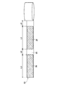
まず,(1)正極板,負極板の製造工程では,図7に示すように正極板21を,また,図8に示すように負極板22を,それぞれ製造する。正極板21の製造工程では,帯状のアルミニウム箔23に,正極活物質24を塗工領域L1にわたって塗工する。次に,未塗工領域L0を残して,次の塗工領域L1に塗工する。これを繰り返して帯状の正極板21を製造する。未塗工領域L0は,上記の電極体11の巻き終わり状態での外周長の半分である。
First, (1) in the manufacturing process of the positive electrode plate and the negative electrode plate, the
また同様に,負極板22の製造工程では,帯状の銅箔25に,負極活物質26を塗工領域L3にわたって塗工する。次に,未塗工領域L0を残して,次の塗工領域L3に塗工する。これを繰り返して帯状の負極板22を製造する。なお,塗工領域L1と塗工領域L3は,電池特性等により決定される1セル分の長さ範囲であり,一般的には正負極で同じ長さにされる。また,この両極板の製造工程には,金属箔にペースト状の活物質を塗り,乾燥・圧延する各工程を含んでいる。
Similarly, in the manufacturing process of the
次に,(2)捲回工程では,それぞれ製造された正極板21と負極板22とをセパレータを挟んで捲回する。内側から順に,正極板21,内側セパレータ27,負極板22,外側セパレータ28の端部を,扁平状の巻き芯にそれぞれ固定する。この巻き初めの端部には未塗工領域は不要である。そして,それぞれに所定のテンションをかけつつ巻き芯を回転させることにより,図9と図10に示すように,扁平状に捲回する。図10は,図9の捲回軸に垂直な方向の断面を模式的に示したものであり,ここでは,既に1セル分の正極板21と負極板22とのほとんどが捲回された状態を示している。
Next, in the (2) winding step, the manufactured
次に,(3)正極板,負極板の終端部設定工程では,内周側の正極板21から処理を行う。まず,図11に示すように,正極板21の塗工領域L1の正極活物質24が完全に巻き取られた後,未塗工領域L0のうち,R部からはみ出ている部分を切り落として仮止めする。これにより,正極板21の巻き終わり端部21eは電極体11のR部に配置される。次に,巻き芯を半回転させ,図12に示すように,負極板22の塗工領域L3の負極活物質26が完全に巻き取られた後,未塗工領域L0のうち,R部からはみ出ている部分を切り落として仮止めする。これにより,負極板22の巻き終わり端部22eは電極体11のR部に配置される。このとき,内側セパレータ27は折り返しておく。
Next, (3) in the terminal portion setting step of the positive electrode plate and the negative electrode plate, the processing is performed from the
次に,(4)セパレータ固定工程では,折り返しておいた内側セパレータ27と外側セパレータ28とを重ね合わせて,1〜3周程度巻き付け,図13に示すようにR部において接着テープ29で固定する。これで,本形態の電極体11が完成した。
Next, in the (4) separator fixing step, the folded
さらに,上記のように製造した電極体11をケース12に封入して本形態のリチウムイオン二次電池10ができる。まず,電極体11の正極板21に正極端子13を,負極板22に負極端子14を,それぞれ接着テープ29側に突出するように接続する。そして,両極端子13,14が接続された電極体11を,ケース12内に挿入する。このとき,両極端子13,14は図1中上方向に向けられるので,接着テープ29も上側に配置される。さらに,電解液を充填して蓋を固定することにより,封入する。これにより,図1に示した本形態の二次電池10が完成した。
Furthermore, the
次に,このように製造された二次電池10に対して,図14に示すように,ポール側突を想定した縦方向の圧壊試験を実施した。この試験では,二次電池10の中央付近へ,図中縦方向の圧壊バー31を所定の荷重で衝突させた。比較のために,ケースの平面部に対向する位置に正極板と負極板の巻き終わり端部が配置されている他は,本形態と同様の二次電池を製造し,比較例とした。その結果は,図15に示すように,比較例では荷重2.4トンで短絡が発生したのに対し,本形態の二次電池10では,荷重3.0トンまでは短絡が発生しなかった。従って,本形態の二次電池10では,ポール側突等の事故に対する耐圧が向上していると言える。
Next, as shown in FIG. 14, the
以上詳細に説明したように,本形態の二次電池10によれば,正極板21と負極板22とにあらかじめ未塗工領域を設けているので,扁平型の巻き芯を使用して捲回した後,未塗工領域内で切り落とすことにより巻き終わり端部21e,22eを所望の位置に配置させることができる。従って,扁平な巻き芯によって扁平に巻かれた電極体11を有する捲回型電池であっても,電池特性等に影響を与えることなく,巻き終わり端部を所望の位置に配置させることができる捲回型電池の製造方法となっている。
As described in detail above, according to the
なお,本形態は単なる例示にすぎず,本発明を何ら限定するものではない。したがって本発明は当然に,その要旨を逸脱しない範囲内で種々の改良,変形が可能である。
例えば,上記の形態では,正極板21の巻き終わり端部21eと負極板22の巻き終わり端部22eとは左右別の側のR部に配置されているが,これらがともに同じ側のR部に配置されるようにしても良い。
また例えば,リチウムイオン二次電池に限らず,捲回型電池であれば適用可能である。
In addition, this form is only a mere illustration and does not limit this invention at all. Therefore, the present invention can naturally be improved and modified in various ways without departing from the gist thereof.
For example, in the above embodiment, the winding
Further, for example, the present invention is not limited to a lithium ion secondary battery, and can be applied to any wound type battery.
10 リチウムイオン二次電池(捲回型電池)
11 電極体(電極捲回体)
12 ケース(容器)
21 正極板
22 負極板
24 正極活物質
26 負極活物質
10 Lithium ion secondary battery (winding battery)
11 Electrode body (electrode winding body)
12 Case (container)
21
Claims (1)
前記正極板と前記負極板とをセパレータで絶縁しつつ扁平形に捲回し,
前記正極板または前記負極板の前記未塗工領域の少なくとも一部が,電極捲回体の外周の,前記電極捲回体を扁平容器に収容したときに前記電極捲回体の外周と前記容器の内面との間に隙間ができるR部上に来たときに,その極板の前記未塗工領域内でかつ前記R部上の位置を切断することにより,その極板の切断後の巻き終わり端を前記R部内に配置することを特徴とする捲回型電池の製造方法。 At least one of the positive electrode plate and the negative electrode plate is provided with an uncoated region where the active material is not applied over a length of one-half or more of the circumference of the electrode winding body,
Winding the positive electrode plate and the negative electrode plate in a flat shape while being insulated by a separator;
Wherein at least a portion of the positive electrode plate or the uncoated area of the negative electrode plate, the outer periphery of the electrode winding body, wherein the container and the outer periphery of the electrode winding body when the electrode winding body is accommodated in a flat container When it comes to the R part where a gap is formed between the inner surface of the electrode plate and the position of the electrode plate in the uncoated region and the position on the R part is cut, the winding after the electrode plate is cut wound type method for producing a battery, characterized by arranging an end edge in the R portion.
Priority Applications (1)
| Application Number | Priority Date | Filing Date | Title |
|---|---|---|---|
| JP2005208494A JP4984450B2 (en) | 2005-07-19 | 2005-07-19 | Winding battery manufacturing method |
Applications Claiming Priority (1)
| Application Number | Priority Date | Filing Date | Title |
|---|---|---|---|
| JP2005208494A JP4984450B2 (en) | 2005-07-19 | 2005-07-19 | Winding battery manufacturing method |
Publications (2)
| Publication Number | Publication Date |
|---|---|
| JP2007026939A JP2007026939A (en) | 2007-02-01 |
| JP4984450B2 true JP4984450B2 (en) | 2012-07-25 |
Family
ID=37787446
Family Applications (1)
| Application Number | Title | Priority Date | Filing Date |
|---|---|---|---|
| JP2005208494A Expired - Fee Related JP4984450B2 (en) | 2005-07-19 | 2005-07-19 | Winding battery manufacturing method |
Country Status (1)
| Country | Link |
|---|---|
| JP (1) | JP4984450B2 (en) |
Families Citing this family (12)
| Publication number | Priority date | Publication date | Assignee | Title |
|---|---|---|---|---|
| JP5132783B2 (en) * | 2007-12-25 | 2013-01-30 | ビーワイディー カンパニー リミテッド | Battery system having a heating terminal |
| JP5222030B2 (en) * | 2008-06-06 | 2013-06-26 | 日立ビークルエナジー株式会社 | Winding type secondary battery and manufacturing method thereof |
| JP4835956B2 (en) | 2008-07-02 | 2011-12-14 | トヨタ自動車株式会社 | battery |
| JPWO2012004886A1 (en) * | 2010-07-09 | 2013-09-02 | 日立ビークルエナジー株式会社 | Secondary battery and method of manufacturing flat wound electrode group |
| JP5589190B2 (en) * | 2011-06-13 | 2014-09-17 | 日立オートモティブシステムズ株式会社 | Secondary battery and electrode assembly manufacturing apparatus |
| WO2013136461A1 (en) * | 2012-03-14 | 2013-09-19 | 株式会社日立製作所 | Non-aqueous electrolyte battery |
| JP5914635B2 (en) * | 2012-03-15 | 2016-05-11 | 日立オートモティブシステムズ株式会社 | Square rechargeable battery module |
| JP2014045001A (en) * | 2012-08-24 | 2014-03-13 | Jsr Corp | Electrode plate for power storage device, electrode group for power storage device, and power storage device |
| JP2016103361A (en) * | 2014-11-27 | 2016-06-02 | 株式会社豊田自動織機 | Power storage device |
| KR102124106B1 (en) * | 2015-11-26 | 2020-06-18 | 주식회사 엘지화학 | Secondary battery |
| US20200321660A1 (en) * | 2017-12-01 | 2020-10-08 | Ningde Amperex Technology Ltd. | Coiled battery cell |
| JP7202338B2 (en) * | 2020-10-22 | 2023-01-11 | プライムプラネットエナジー&ソリューションズ株式会社 | battery |
Family Cites Families (3)
| Publication number | Priority date | Publication date | Assignee | Title |
|---|---|---|---|---|
| JP2003086233A (en) * | 2001-09-07 | 2003-03-20 | Mitsubishi Electric Corp | Flat battery and its manufacturing method |
| JP4097443B2 (en) * | 2002-03-27 | 2008-06-11 | 三洋電機株式会社 | Lithium secondary battery |
| JP4502616B2 (en) * | 2003-09-30 | 2010-07-14 | 三洋電機株式会社 | Batteries having a film-like outer package |
-
2005
- 2005-07-19 JP JP2005208494A patent/JP4984450B2/en not_active Expired - Fee Related
Also Published As
| Publication number | Publication date |
|---|---|
| JP2007026939A (en) | 2007-02-01 |
Similar Documents
| Publication | Publication Date | Title |
|---|---|---|
| JP4984450B2 (en) | Winding battery manufacturing method | |
| US20130084479A1 (en) | Secondary battery | |
| WO2014097586A1 (en) | Cylindrical secondary battery and method for manufacturing same | |
| US20120141850A1 (en) | Middle or large sized battery | |
| WO2017141613A1 (en) | Rectangular secondary battery | |
| JPH11265703A (en) | Battery and its manufacture | |
| JP7037725B2 (en) | Sealed battery | |
| EP1717894B1 (en) | Cylindrical lithium secondary battery and method of fabricating the same | |
| JP2023530203A (en) | Electrode assembly, battery, device and method of manufacturing electrode assembly | |
| US20240234931A9 (en) | Battery, and battery pack and vehicle including the same | |
| CN219457721U (en) | Battery winding core, cylindrical battery, battery module and electricity utilization device | |
| KR101712449B1 (en) | A hollow-shaped jelly roll tap plate assembly | |
| JP2019523975A (en) | Electrode for electrochemical bundle of metal ion storage battery or supercapacitor, related bundle manufacturing method and storage battery | |
| JP2010205429A (en) | Nonaqueous electrolyte secondary battery and electrode for the same | |
| CN222775412U (en) | Cells and Batteries | |
| KR100307452B1 (en) | Electrode of secondary battery | |
| US7687196B2 (en) | Prismatic battery and method for manufacturing the same | |
| JP3302200B2 (en) | Sealed rectangular non-aqueous electrolyte battery | |
| KR100529098B1 (en) | Secondary battery | |
| KR101472878B1 (en) | Winder Using for Secondary Battery of Novel Structure | |
| KR100813829B1 (en) | Electrode Jelly Roll for Secondary Battery | |
| JP7836872B2 (en) | Flat wound electrode body, battery, battery module, and method for manufacturing the flat wound electrode body and battery. | |
| JPH09213361A (en) | Manufacture of spiral plate group | |
| JP4978530B2 (en) | Cylindrical battery and manufacturing method thereof | |
| US20240405394A1 (en) | Power storage cell |
Legal Events
| Date | Code | Title | Description |
|---|---|---|---|
| A621 | Written request for application examination |
Free format text: JAPANESE INTERMEDIATE CODE: A621 Effective date: 20080709 |
|
| A977 | Report on retrieval |
Free format text: JAPANESE INTERMEDIATE CODE: A971007 Effective date: 20110420 |
|
| A131 | Notification of reasons for refusal |
Free format text: JAPANESE INTERMEDIATE CODE: A131 Effective date: 20110426 |
|
| A521 | Request for written amendment filed |
Free format text: JAPANESE INTERMEDIATE CODE: A523 Effective date: 20110622 |
|
| TRDD | Decision of grant or rejection written | ||
| A01 | Written decision to grant a patent or to grant a registration (utility model) |
Free format text: JAPANESE INTERMEDIATE CODE: A01 Effective date: 20120403 |
|
| A01 | Written decision to grant a patent or to grant a registration (utility model) |
Free format text: JAPANESE INTERMEDIATE CODE: A01 |
|
| A61 | First payment of annual fees (during grant procedure) |
Free format text: JAPANESE INTERMEDIATE CODE: A61 Effective date: 20120416 |
|
| R151 | Written notification of patent or utility model registration |
Ref document number: 4984450 Country of ref document: JP Free format text: JAPANESE INTERMEDIATE CODE: R151 |
|
| FPAY | Renewal fee payment (event date is renewal date of database) |
Free format text: PAYMENT UNTIL: 20150511 Year of fee payment: 3 |
|
| LAPS | Cancellation because of no payment of annual fees |