JP4986580B2 - Soundproof partition - Google Patents
Soundproof partition Download PDFInfo
- Publication number
- JP4986580B2 JP4986580B2 JP2006306120A JP2006306120A JP4986580B2 JP 4986580 B2 JP4986580 B2 JP 4986580B2 JP 2006306120 A JP2006306120 A JP 2006306120A JP 2006306120 A JP2006306120 A JP 2006306120A JP 4986580 B2 JP4986580 B2 JP 4986580B2
- Authority
- JP
- Japan
- Prior art keywords
- sound
- partition
- case
- main body
- absorbing member
- Prior art date
- Legal status (The legal status is an assumption and is not a legal conclusion. Google has not performed a legal analysis and makes no representation as to the accuracy of the status listed.)
- Expired - Fee Related
Links
Images


Landscapes
- Building Environments (AREA)
Description
本発明は、例えば建物の部屋間を仕切るために用いられ、各部屋間の音の伝播を防止するための防音仕切りに関する。 The present invention relates to a soundproof partition that is used, for example, for partitioning rooms in a building, and that prevents the propagation of sound between rooms.
従来、例えば建物に設けられる防音仕切りとして、建物に形成された窓に設けられる防音カーテンが知られている。この防音カーテンは、通常遮光のために用いられるカーテンに比べて高い面密度を有する布地素材からなる。これにより、空気が防音カーテンを通過することが抑制されるので、空気中を伝播する音の一部が防音カーテンで反射する。従って、建物内の音が窓を経て屋外に漏れること及び屋外の音が窓を経て建物内に入ってくることが抑制される。 Conventionally, for example, as a soundproof partition provided in a building, a soundproof curtain provided in a window formed in the building is known. This soundproof curtain is made of a fabric material having a higher surface density than a curtain normally used for light shielding. Thereby, since it is suppressed that air passes a soundproof curtain, a part of sound which propagates in the air reflects in a soundproof curtain. Therefore, it is suppressed that the sound in the building leaks to the outside through the window and the outdoor sound enters the building through the window.
また、この防音カーテンとは別に、一組のレースカーテン間にプラスチックフィルムを挟み込んだ防音カーテンが提案されている(例えば、特許文献1参照。)。この防音カーテンによれば、特に高音域の音から受ける音圧によりプラスチックフィルムが振動したとき、その振動を各レースカーテンのクッション作用により吸収することができるので、高音が防音カーテンを経て伝播することを防止することができる。
しかしながら、布地素材からなる防音カーテンは、音の一部を反射させ、音の一部の通過を許すことから、音の伝播を防音カーテンで十分に抑制することができない。 However, a soundproof curtain made of a fabric material reflects a part of the sound and allows a part of the sound to pass therethrough. Therefore, the sound propagation cannot be sufficiently suppressed by the soundproof curtain.
また、一組のレースカーテン間にプラスチックフィルムが挟み込まれた防音カーテンでは、各レースカーテン自体は防音性能を有していないため、音の一部がプラスチックフィルムを経て伝播した場合、通過した音をレースカーテンで遮断又は吸収することができない。このため、この場合も、音の伝播を防音カーテンで十分に抑制することができない。 In addition, in a soundproof curtain in which a plastic film is sandwiched between a pair of lace curtains, each lace curtain itself does not have soundproofing performance, so if part of the sound propagates through the plastic film, It cannot be blocked or absorbed by the lace curtain. For this reason, also in this case, the propagation of sound cannot be sufficiently suppressed by the soundproof curtain.
そこで、本発明の目的は、音の伝播をより確実に抑制することができる仕切りの防音構造を提供することにある。 Accordingly, an object of the present invention is to provide a soundproof structure for a partition that can more reliably suppress sound propagation.
上記課題を解決するために、請求項1に記載の発明は、全体に板状をなした仕切り本体を備える防音仕切りであって、前記仕切り本体は、その一方の面を構成し、該一方の面側で発生した音の少なくとも一部の伝播を遮断する遮音部材と、該遮音部材の前記仕切り本体の他方の面側に位置する面に設けられ、前記遮音部材を経て該遮音部材の前記仕切り本体の前記他方の面側に伝播した音を吸収するための吸音部材とを備えることを特徴とする。
In order to solve the above-mentioned problem, the invention described in
請求項2に記載の発明は、請求項1に記載の発明において、前記遮音部材は所定の面密度を有する布地素材からなり、前記吸音部材は互いに絡み合った複数の繊維からなる綿状体であることを特徴とする。
The invention according to
前記仕切り本体は、前記遮音部材を含む一対の遮音部材と、前記吸音部材を含む一対の吸音部材とを備え、前記各遮音部材は、それぞれ前記仕切り本体の前記一方の面及び前記他方の面を構成し、前記仕切り本体の板厚方向に互いに間隔をおいて配置されており、前記各吸音部材は、それぞれ前記各遮音部材の互いに対向する面に設けられることを特徴とする。 Before Symbol partition body has a pair of sound insulating members containing said sound insulating member, wherein a pair of the sound absorbing member including the sound absorbing member, wherein each of the sound insulating member, the one surface and the other surface of each of the partition body Are arranged at intervals in the plate thickness direction of the partition main body, and the respective sound absorbing members are respectively provided on surfaces of the respective sound insulating members facing each other.
少なくとも一方の前記遮音部材には、該遮音部材の前記吸音部材が設けられた前記面と反対側に位置する面から前記仕切り本体の外方へ突出し且つ前記遮音部材の前記面に沿って互いに同一方向に伸びる100mm以上の高さの複数の凸部が互いに間隔をおいて形成されており、該各凸部の幅寸法は、それぞれ前記各凸部の先端から前記遮音部材に向けて漸増していることを特徴とする。 On one of the sound insulating member even without low, along the surface of the sound absorbing member is protruded from the surface located opposite the surface formed outwardly of the partition body and the sound insulating member of the shielding sound member A plurality of convex portions with a height of 100 mm or more extending in the same direction are formed at intervals, and the width dimension of each convex portion gradually increases from the tip of each convex portion toward the sound insulation member. It is characterized by that.
前記各吸音部材間には空気層が形成されていてもよい。 Between before Symbol the sound absorbing member may be formed an air layer.
前記吸音部材の前記遮音部材側の面と反対側に位置する面を覆うシート部材を備えていることを特徴とする。 Before SL, characterized in that it includes the sound insulating member side surface opposite to the Hare covering a surface located on the side sheet member of the sound absorbing member.
前記シート部材はビニルシートであってもよい。 Before Symbol sheet member may be I vinyl sheet Der.
前記シート部材は、二枚の樹脂フィルム間に空気が封入されたエアーキャップであってもよい。 Before SL sheet member may me air cap der air is sealed between two sheets of resin films.
請求項1に記載の発明によれば、仕切り本体が、仕切り本体の一方の面側で発生した音の少なくとも一部の伝播を遮断する遮音部材を備えることから、仕切り本体の前記一方の面側で音が発生したとき、その音の少なくとも一部が仕切り本体の他方の面側に伝播することを遮音部材により阻止することができる。これにより、布地素材からなる従来の防音カーテンと同様に、前記音が仕切り本体の前記一方の面側から前記他方の面側に音が漏れることが抑制される。 According to the first aspect of the present invention, since the partition main body includes a sound insulation member that blocks the propagation of at least a part of the sound generated on one surface side of the partition main body, the one surface side of the partition main body is provided. When a sound is generated in the sound insulation member, it is possible to prevent the sound insulation member from propagating at least a part of the sound to the other surface side of the partition main body. Thereby, like the conventional soundproof curtain which consists of a textile material, it is suppressed that the said sound leaks from the said one surface side of a partition main body to the said other surface side.
更に、遮音部材の仕切り本体の他方の面側に位置する面に、遮音部材を経て仕切り本体の前記他方の面側に伝播した音を吸収するための吸音部材が設けられていることから、仕切り本体の前記一方の面側で発生した音の一部が遮音部材により遮断されることなく仕切り本体の前記他方の面側に伝播した場合でも、遮音部材を通過した音を吸音部材により吸収することができる。これにより、一枚の布地素材からなる従来の防音カーテンや一組のレースカーテン間にプラスチックフィルムが挟み込まれた防音カーテンに比べて、音の伝播をより確実に抑制することができる。 Furthermore, since the sound absorbing member for absorbing the sound propagated to the other surface side of the partition body through the sound insulation member is provided on the surface located on the other surface side of the partition body of the sound insulation member, the partition Even when a part of the sound generated on the one surface side of the main body propagates to the other surface side of the partition main body without being blocked by the sound insulating member, the sound passing through the sound insulating member is absorbed by the sound absorbing member. Can do. Thereby, the propagation of sound can be more reliably suppressed as compared with a conventional soundproof curtain made of a single fabric material or a soundproof curtain in which a plastic film is sandwiched between a pair of lace curtains.
請求項2に記載の発明によれば、遮音部材は所定の面密度を有する布地素材からなることから、仕切り本体の前記一方の面側で発生した音が遮音部材に到達したとき、音の一部は遮音部材の面密度の大きさに応じて遮音部材で例えば反射し、音の一部は遮音部材の内部を通って遮音部材の仕切り本体の前記他方の面側に伝播する。 According to the second aspect of the present invention, since the sound insulating member is made of a cloth material having a predetermined surface density, when the sound generated on the one surface side of the partition main body reaches the sound insulating member, The part is reflected by the sound insulation member according to the surface density of the sound insulation member, for example, and part of the sound propagates through the inside of the sound insulation member to the other surface side of the partition main body of the sound insulation member.
また、遮音部材の仕切り本体の前記他方の面側に位置する面に設けられた吸音部材が互いに絡み合った複数の繊維からなる綿状体であることから、吸音部材は多孔質構造を有する。これにより、遮音部材を通過して吸音部材の内部に入ると、吸音部材の各繊維間の空気は、それぞれ音から受ける音圧により吸音部材の仕切り本体の前記他方の面側に向けて吸音部材の内方に押し込まれ、更に、吸音部材の仕切り本体の前記他方の面側に存在する空気から受ける気圧により吸音部材の内方に押し戻される。この繰り返しにより、吸音部材の各繊維間の空気は、遮音部材を通過した音の周波数と同一の周波数で単振動する。この単振動により各繊維間の空気と各繊維との間に摩擦が生じ、この摩擦により音のエネルギーが熱エネルギーに変換される。これにより、遮音部材を通過した周波数成分の音が吸収される。 The sound absorbing member has a porous structure because the sound absorbing member provided on the other surface of the partition body of the sound insulating member is a cotton-like body made of a plurality of fibers intertwined with each other. Thereby, when passing through the sound insulation member and entering the inside of the sound absorption member, the air between the fibers of the sound absorption member is directed toward the other surface of the partition main body of the sound absorption member by the sound pressure received from the sound. Is further pushed back inward by the air pressure received from the air present on the other surface side of the partition main body of the sound absorbing member. By repeating this, the air between the fibers of the sound absorbing member simply vibrates at the same frequency as the sound that has passed through the sound insulating member. This simple vibration causes friction between the air between the fibers and the fibers, and the sound energy is converted into thermal energy by the friction. Thereby, the sound of the frequency component which passed the sound insulation member is absorbed.
従って、仕切り本体の前記一方の面側で発生した音が仕切り本体の前記他方の面側に向けて伝播することを遮音部材及び吸音部材により確実に抑制することができる。 Therefore, the sound insulation member and the sound absorbing member can reliably suppress the sound generated on the one surface side of the partition body from propagating toward the other surface side of the partition body.
また、遮音部材が互いに絡み合った複数の繊維からなる綿状体であることから、例えば高い面密度を有する布地素材と同一の大きさで比べた場合、一般的に綿状体である遮音部材の重量は布地素材の重量よりも軽い。 Further, since the sound insulation member is a cotton-like body composed of a plurality of fibers intertwined with each other, for example, when compared with the same size as a fabric material having a high surface density, the sound insulation member that is generally a cotton-like body The weight is lighter than the weight of the fabric material.
従来、例えば布地素材からなる防音カーテンの防音性をより向上させるために、防音カーテンの厚さを厚くすることが考えられる。しかしながら、防音カーテンの厚さを厚くすると、防音カーテン全体の重量が重くなるため、防音カーテンの可動性が低下する。 Conventionally, in order to further improve the soundproofing property of a soundproof curtain made of, for example, a fabric material, it is conceivable to increase the thickness of the soundproof curtain. However, when the thickness of the soundproof curtain is increased, the weight of the entire soundproof curtain is increased, so that the mobility of the soundproof curtain is lowered.
これに対し、本発明によれば、布地素材からなる遮音部材に設けられた吸音部材が綿状体であることから、前記したように、遮音部材の重量は布地素材の重量よりも軽いことから、遮音部材の厚さを従来のように単に厚くした場合程、仕切り本体全体の重量が重くなることはない。これにより、重量の増加による仕切り本体の従来のような可動性の低下を確実に防止することができる。 On the other hand, according to the present invention, since the sound absorbing member provided on the sound insulating member made of the fabric material is a cotton-like body, as described above, the weight of the sound insulating member is lighter than the weight of the fabric material. The weight of the entire partition body does not increase as much as when the thickness of the sound insulation member is simply increased as in the prior art. Thereby, the fall of the conventional mobility of the partition main body by the increase in a weight can be prevented reliably.
また、仕切り本体が一対の遮音部材と一対の吸音部材とを備え、各遮音部材は、それぞれ仕切り本体の前記一方の面及び前記他方の面を構成し、仕切り本体の板厚方向に互いに間隔をおいて配置されており、各吸音部材は、それぞれ各遮音部材の互いに対向する面に設けられていることから、各遮音部材の遮音作用及び各吸音部材の吸音作用により、仕切り本体の前記一方の面側と前記他方の面側とのそれぞれで発生した音が仕切り本体の前記一方の面側と前記他方の面側との間で伝播することを確実に抑制することができる。 The partition body includes a pair of sound insulation members and a pair of sound absorption members, and each sound insulation member constitutes the one surface and the other surface of the partition body, and is spaced from each other in the thickness direction of the partition body. Since each sound absorbing member is provided on the surface of each sound insulating member facing each other, the sound insulating action of each sound insulating member and the sound absorbing action of each sound absorbing member cause the one of the partition main bodies to It is possible to reliably suppress the sound generated on each of the surface side and the other surface side from propagating between the one surface side and the other surface side of the partition main body.
さらに、少なくとも一方の遮音部材には、該遮音部材の吸音部材が設けられた面と反対側に位置する面から仕切り本体の外方へ突出し且つ遮音部材の前記面に沿って互いに同一方向に伸びる複数の凸部が互いに間隔をおいて形成されており、各凸部の幅寸法は、それぞれ各凸部の先端から遮音部材に向けて漸増していることから、例えば仕切り本体の前記一方の面側で発生した音が前記一方の遮音部材に到達したとき、音の一部は、互いに隣接して形成された各凸部の側面に反射することにより、互いに隣接した各凸部間を前記一方の遮音部材に向けて減衰振動する。これにより、遮音部材に到達した音のうち遮音部材の内方に入射することなく遮音部材で伝播が遮断される音の大部分が、遮音部材の前記面で反射することなく各凸部の減衰作用により消滅するので、遮音部材により遮断された音が遮音部材で反射することによる仕切り本体の前記一方の面側への大きな残響の発生が防止される。従って、大きな残響が生じることにより不快さを招くことを、確実に防止することができる。 Further , at least one of the sound insulating members protrudes outward from the surface of the partition body from the surface of the sound insulating member opposite to the surface on which the sound absorbing member is provided and extends in the same direction along the surface of the sound insulating member. A plurality of convex portions are formed at intervals from each other, and the width dimension of each convex portion is gradually increased from the tip of each convex portion toward the sound insulating member, for example, the one surface of the partition main body When the sound generated on the side reaches the one sound insulation member, a part of the sound is reflected on the side surfaces of the respective protrusions formed adjacent to each other, so that the one between the adjacent protrusions is Damping vibration toward the sound insulation member. As a result, most of the sound that has reached the sound insulation member and is blocked by the sound insulation member without being incident on the inside of the sound insulation member is attenuated by the projections without being reflected by the surface of the sound insulation member. Since it disappears due to the action, the occurrence of large reverberation on the one surface side of the partition main body due to the sound blocked by the sound insulating member being reflected by the sound insulating member is prevented. Therefore, it is possible to surely prevent unpleasantness caused by large reverberation.
また、各吸音部材間に空気層が形成されていれば、各吸音部材を経て各吸音部材の遮音部材側からその反対側に音がたとえ伝播されたとしても、その音が空気層に入ったとき、空気層内の空気が音から受ける音圧により両吸音部材間
で振動し、これにより、空気と各吸音部材との間に生じる摩擦により音のエネルギーが熱エネルギーに変換されて各吸音部材を通過した周波数成分の音が吸収されるので、一方の吸音部材を通過した音が他方の吸音部材に入ることをより確実に抑制することができる。
Further , if an air layer is formed between the sound absorbing members, even if the sound is propagated from the sound insulating member side of each sound absorbing member to the opposite side through each sound absorbing member, the sound enters the air layer. When the air in the air layer is vibrated between the sound absorbing members due to the sound pressure received from the sound, the sound energy is converted into heat energy by the friction generated between the air and each sound absorbing member, and each sound absorbing member Since the sound of the frequency component that has passed through is absorbed, it is possible to more reliably suppress the sound that has passed through one of the sound absorbing members from entering the other sound absorbing member.
そして、吸音部材の遮音部材側の面と反対側に位置する面には、該面を覆うシート部材が設けられていることから、前記一方の吸音部材を経て該吸音部材の遮音部材側からその反対側に音がたとえ伝播されたとしても、その音がシート部材に当たったとき、音から受ける音圧によりシート部材が各吸音部材を通過した音の周波数と同一の周波数でいわゆる膜振動し、このシート部材の膜振動が前記一方の吸音部材の変形により吸収されるので、前記一方の吸音部材を通過した音が他方の吸音部材に入ることをより確実に抑制することができる。 And since the sheet member covering the surface is provided on the surface of the sound absorbing member opposite to the surface on the sound insulating member side , the sound absorbing member side of the sound absorbing member passes through the one sound absorbing member. Even if the sound is propagated to the opposite side, when the sound hits the sheet member, so-called membrane vibration occurs at the same frequency as the frequency of the sound that the sheet member has passed through each sound absorbing member due to the sound pressure received from the sound, Since the membrane vibration of the sheet member is absorbed by the deformation of the one sound absorbing member, it is possible to more reliably suppress the sound that has passed through the one sound absorbing member from entering the other sound absorbing member.
また、シート部材がビニルシートであれば、少なくとも前記一方の吸音部材の前記面にビニルシートを設けることにより、前記一方の吸音部材を通過した音が他方の吸音部材に入ることを容易に抑制することができる。 Further , if the sheet member is a vinyl sheet, by providing a vinyl sheet on at least the surface of the one sound absorbing member, the sound that has passed through the one sound absorbing member is easily suppressed from entering the other sound absorbing member. be able to.
さらに、シート部材が二枚の樹脂フィルム間に空気が封入されたエアーキャップであれば、前記一方の吸音部材を経て該吸音部材の遮音部材側からその反対側に伝播した音がエアーキャップに当たったとき、エアーキャップ全体に生じる膜振動を前記一方の吸音部材により吸収することにより前記音を遮断することができることに加えて、エアーキャップの両樹脂フィルム間に封入された空気が前記音から受ける音圧により両樹脂フィルム間で前記音の周波数と同一の周波数で振動し、この振動により両樹脂フィルム間の空気と各樹脂フィルムとの間に摩擦が生じ、この摩擦により音のエネルギーが熱エネルギーに変換される。これにより、前記一方の吸音部材を通過した周波数成分の音が吸収されるので、前記一方の吸音部材を通過した音が他方の吸音部材に入ることをより確実に抑制することができる。 Furthermore, Der air cap sheet member is sealed air between two sheets of resin films lever, sound propagating on the opposite side from the sound insulating member side of said sound absorbing member and the through one of the sound absorbing member is in the air cap In addition to being able to block the sound by absorbing the membrane vibration generated in the entire air cap with the one sound absorbing member, the air enclosed between the two resin films of the air cap is removed from the sound. The received sound pressure vibrates between the two resin films at the same frequency as that of the sound, and this vibration causes friction between the air between the two resin films and each resin film. Converted into energy. Thereby, since the sound of the frequency component that has passed through the one sound absorbing member is absorbed, it is possible to more reliably suppress the sound that has passed through the one sound absorbing member from entering the other sound absorbing member.
本発明を図示の実施例に沿って説明する。 The present invention will be described with reference to the illustrated embodiments.
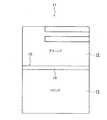
図1は、建物11に設けられたダイニング12とリビング13との間を仕切るための間仕切に本発明に係る防音仕切り10を適用した例を示す。
FIG. 1 shows an example in which a
本発明に係る防音仕切り10は、図1に示すように、ダイニング12及びリビング13間に配置される仕切り本体14を備える。
As shown in FIG. 1, the
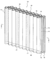
仕切り本体14は、図2に示すように、全体に板状をなしており、一対の枠組15を備える。
As shown in FIG. 2, the partition
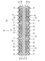
各枠組み15は、互いに間隔をおく且つ建物11の上下方向に伸びるように配置された一対の縦枠16と、該各縦枠に平行に且つ該各縦枠に間隔をおき更に互いに間隔をおいて各縦枠16間に配置された一対の中枠17と、該各中枠及び各縦枠16の各上端部及び各下端部をそれぞれ連結する一対の横枠18とをそれぞれ備え、全体に矩形状をなしている。各枠組み15は、図3に示すように、一方の枠組15の各縦枠16、各中枠17及び各横枠18が他方のそれらに整合し且つ仕切り本体14の板厚方向に互いに間隔がおかれるように配置されている。仕切り本体14は、各枠組み15がそれぞれダイニング12及びリビング13間を横切るように配置されている。
Each
また、仕切り本体14は、図2及び図3に示すように、各枠組み15に設けられ、ダイニング12及びリビング13内で発生した音の少なくとも一部の伝播を遮断する一対の遮音部材19を備える。
As shown in FIGS. 2 and 3, the partition
各遮音部材19は、図示の例では、それぞれ例えば絨毯のような布地素材からなる。各遮音部材19の面密度の値は、図示の例では、それぞれ2.5kg/m2に設定されており、各遮音部材19の遮音率の値は、図示の例では、それぞれ0.7以上に設定されている。各遮音部材19のうち一方の遮音部材19は、ダイニング12側に配置された一方の枠組み15のダイニング12に面する表面15aに該表面を覆うように設けられている。また、他方の遮音部材19は、リビング13側に配置された他方の枠組み15のリビング13に面する表面15aに設けられている。これにより、各遮音部材19はそれぞれ板状の仕切り本体14の各面を構成する。
Each
各遮音部材19のダイニング12及びリビング13に面する表面19aには、それぞれ該各表面からダイニング12及びリビング13内へ突出し且つ各遮音部材19の表面19aに沿って互いに同一方向に伸びる複数の凸部20が互いに間隔をおいて形成されている。各遮音部材19は、図示の例では、その横断面がほぼ波形をなすように形成されており、各凸部20は、それぞれ波を構成する各山で構成されており、それぞれ建物11の上下方向に沿って伸びる。各凸部20が波を構成する各山で構成されていることから、各凸部20の幅寸法は、それぞれ該各凸部の先端20aから各遮音部材19の表面19aに向けて漸増する。波を構成する各山間のピッチすなわち各凸部20の先端20a間の間隔L(図3参照。)は、図示の例では、50〜1800mmの範囲内で設定されており、各凸部20の突出量である高さH(図3参照。)は、1〜300mmの範囲内で設定されている。
The
更に、仕切り本体14は、ダイニング12及びリビング13内からそれぞれに対応した各遮音部材19を通過して該各遮音部材の反対側に伝播した音を吸収するための一対の吸音部材21を備える。
Furthermore, the partition
各吸音部材21は、図3に示す例では、各枠組み15の各縦枠16、各中枠17及び各横枠18により規定された各空間S内に該各空間をそれぞれ充填するように設けられている。各吸音部材21は、図示の例では、それぞれグラスウールで構成されている。グラスウールは、従来よく知られているように、複数のガラス製の繊維を互いに絡み合わせることにより形成された綿状体である。各吸音部材21の面密度は、図示の例では、それぞれ5〜20kg/m2の範囲内で設定されており、各吸音部材21の厚さ寸法は、それぞれ10〜30mmの範囲内で設定されている。各吸音部材21の面密度が5kg/m2以下である場合、又は、各吸音部材21の厚さ寸法が10mm以下である場合、各吸音部材21の吸音効果が低下してしまい、また、各吸音部材21の面密度が20kg/m2以上である場合、又は各吸音部材21の厚さ寸法が30mm以上である場合、各吸音部材21の重量が過度に重くなるため、仕切り本体14の可動性が低下するが、本実施例では、前記したように、各吸音部材21の面密度がそれぞれ5〜20kg/m2の範囲内で設定されており、各吸音部材21の厚さ寸法がそれぞれ10〜30mmの範囲内で設定されていることから、吸音効果の低下及び仕切り本体14の可動性の低下が防止される。各吸音部材21は、それぞれ各遮音部材19に例えば図示しない糸により縫合されることにより各遮音部材19に当接した状態に保持されている。
In the example shown in FIG. 3, each
各吸音部材21が充填された各枠組み15間には、前記したように間隔がおかれていることから、両吸音部材21間には空気層Kが形成される。
Since the intervals between the
各枠組み15の表面15aと反対側に位置する裏面15bには、図示の例では、それぞれ該各裏面を覆うシート部材が設けられている。各シート部材は、図示の例では、それぞれビニルシート23で構成されており、各縦枠16、各中枠17及び各横枠18にそれぞれ例えば図示しない釘のような締結具により固定されている。各ビニルシート23の面密度の値は、図示の例では、0.62kg/m2に設定されている。各枠組み15の裏面15bが各ビニルシート23よって覆われることにより、各枠組み15内に充填された各吸音部材21の互いに対向する裏面21bがそれぞれ各ビニルシート23により覆われる。
In the illustrated example, a sheet member that covers each back surface is provided on the
例えばダイニング12内で音が発生時にその音が仕切り本体14に到達したとき、音の一部は、前記一方の遮音部材19に形成された各凸部20に当たる。このとき、各凸部20の幅寸法が、前記したように、それぞれ各凸部20の先端20aから各遮音部材19の表面19aに向けて漸増していることから、各凸部20に当たった音は、互いに隣接して形成された各凸部20の側面20b(図3参照。)に反射することにより、互いに隣接した各凸部20間を前記一方の遮音部材19に向けて減衰振動して消滅する。
For example, when sound is generated in the
また、ダイニング12内で発生した音の一部は、ダイニング12に面する前記一方の遮音部材19の面密度の大きさに応じて、前記遮音部材19により遮断されることなく前記一方の遮音部材19の内部に進入し、該遮音部材内を通って前記一方の枠組み15に向けて前記一方の遮音部材19内から出射される。
Further, a part of the sound generated in the
前記一方の遮音部材19を通過した音は、該遮音部材が設けられた前記一方の枠組み15内に充填された一方の吸音部材21内に入る。各吸音部材21が、前記したように、互いに絡み合った複数の繊維からなる綿状体であることから、各吸音部材21はそれぞれ多孔質構造を有する。従って、前記一方の吸音部材21内に音が入ったとき、該吸音部材の各繊維間の空気は、それぞれ音から受ける音圧により前記一方の吸音部材21の内方に押し込まれ、更に、前記一方の吸音部材21の裏面21b側に存在する空気から受ける気圧により前記一方の吸音部材21の内方に押し戻される。この繰り返しにより、前記一方の吸音部材21の各繊維間の空気は、各繊維間で前記一方の遮音部材19を通過した音の周波数と同一の周波数で単振動する。この単振動により各繊維間の空気と各繊維との間に摩擦が生じ、この摩擦により音のエネルギーが熱エネルギーに変換される。これにより、前記一方の遮音部材19を通過した周波数成分の音が前記一方の吸音部材21で吸収される。
The sound that has passed through the one
前記一方の遮音部材19を通過した音を前記一方の吸音部材21で吸収し切れず、前記一方の吸音部材21を経て該吸音部材の裏面21b側に音が伝播された場合、各枠組み15の裏面15bに、前記したように、各吸音部材21の裏面21bをそれぞれ覆うビニルシート23が設けられていることから、前記一方の吸音部材21を通過した音が該吸音部材の裏面21bを覆うビニルシート23に当たったとき、音から受ける音圧によりビニルシート23が該ビニルシートに当たった音の周波数と同一の周波数でいわゆる膜振動する。このビニルシート23の膜振動が前記一方の吸音部材21の変形により吸収されるので、ビニルシート23に当たった音が該ビニルシートのリビング13側に伝播することが抑制される。
When the sound that has passed through the one
更に、ビニルシート23で音を遮断し切れず、ビニルシート23を経て該ビニルシートのリビング13側に音が伝播した場合、両吸音部材21間すなわち両ビニルシート23間に空気層Kが形成されていることから、ビニルシート23を通過した音は空気層Kに入る。音が空気層Kに入ったとき、空気層K内の空気が音から受ける音圧により両ビニルシート23間で振動する。これにより、空気と各ビニルシート23との間に生じる摩擦により音のエネルギーが熱エネルギーに変換されて各ビニルシート23を通過した周波数成分の音が吸収される。これにより、ビニルシート23を通過した音が該ビニルシートのリビング13側に伝播することが抑制される。
Furthermore, when the sound is not completely blocked by the
これにより、ダイニング12内で発生した音がリビング13内に伝播することが抑制される。
Thereby, it is suppressed that the sound generated in the
リビング13内で音が発生した場合も、リビング13側に配置された遮音部材19、吸音部材21及びビニルシート23と空気層Kとにより、リビング13で発生した音がダイニング12内に伝播することを、上記したと同様に抑制することができる。
Even when sound is generated in the
図4は、ダイニング12内で音が発生したときの、音の中心周波数(単位はHzである。)と、ダイニング12内で測定した平均音圧レベル(単位はdBである。)の値からリビング13内で測定した平均音圧レベルの値を差し引いた値との関係を、本実施例に係る各凸部20がそれぞれ両遮音部材19に形成された場合(以下、ケース1と称す。)、本実施例に係る各凸部20がそれぞれ前記一方の遮音部材19に形成された場合(以下、ケース2と称す。)及び本実施例に係る凸部20がいずれの遮音部材19にも形成されることなく各遮音部材19がそれぞれ平坦である場合(以下、ケース3と称す。)のそれぞれに関して示すグラフである。
FIG. 4 shows the sound center frequency (unit: Hz) and the average sound pressure level (unit: dB) measured in the
図4の横軸は音の中心周波数を示し、縦軸はダイニング12及びリビング13間の平均音圧レベル差を示す。図4には、ケース1における平均音圧レベル差の変化が特性線24で示されており、ケース2における平均音圧レベルの変化が特性線25で示されており、ケース3における平均音圧レベルの変化が特性線26で示されている。
The horizontal axis of FIG. 4 indicates the center frequency of the sound, and the vertical axis indicates the average sound pressure level difference between the
図4に示すグラフに基づいてケース2とケース3とを比較すると、250Hz〜2KHzの中低音域では、ケース2における平均音圧レベル差の値がケース3におけるそれよりも大きくなっており、2KHz以上の高音域では、ケース2における平均音圧レベル差の値とケース3におけるそれとが互いにほぼ等しくなっている。このことから、前記した中低音域では、ケース2の方がケース3よりもダイニング12内で発生した音がリビング13内に伝播し難く、前記した高音域では、ダイニング12からリビング13への音の伝播のし難さがほぼ等しいことが分かる。すなわち、前記一方の遮音部材19に複数の凸部20を形成した場合、両遮音部材19が平坦である場合に比べて仕切り本体14全体の防音効果が前記した中低音域で向上する。
When comparing the
更に、図4に示すグラフに基づいてケース1とケース2とを比較すると、全音域において、ケース1における平均音圧レベル差の値がケース2におけるそれよりも大きくなっている。このことから、全音域において、ケース1の方がケース2よりもダイニング12内で発生した音がリビング13内により伝播し難いことが分かる。すなわち、両遮音部材19にそれぞれ複数の凸部20を形成した場合、前記一方の遮音部材19に各凸部20が形成された場合に比べて仕切り本体14全体の防音効果が全音域で更に向上する。
Furthermore, when comparing
以下、図5乃至図8に、上記した実施例に係る防音仕切り10において各凸部20の高さH及び/又は間隔Lをそれぞれ変化させたときの音響透過損失の変化を測定した結果を示す。音響透過損失は、従来よく知られているように、入射した音と仕切り本体14を透過した音との音圧レベルの差であり、仕切り本体14の透過率に反比例する。
Hereinafter, FIGS. 5 to 8 show the results of measuring the change in sound transmission loss when the height H and / or the interval L of each
また、図5乃至図8に示す例では、音響インテンシティ法を用いて音響透過損失を測定している。音響インテンシティ法は、従来よく知られているように、図示しない残響室と無響室との間に本発明に係る仕切り本体14を配置し、前記残響室内に配置された音源からの音が仕切り本体14を通過したときの前記無響室内での音圧レベルを測定する方法である。
In the examples shown in FIGS. 5 to 8, the sound transmission loss is measured using the sound intensity method. As is well known in the art, the sound intensity method includes a partition
図5は、各凸部20の間隔Lを一定にして各凸部20の高さHを変化させたときの音の周波数(単位はHzである。)と音響透過損失(単位はdBである。)との関係を示すグラフである。
FIG. 5 shows the sound frequency (unit: Hz) and sound transmission loss (unit: dB) when the height H of each
図5に示す例では、各凸部20の間隔Lを450mmに固定したときに、各凸部20の高さHがそれぞれ100mmである場合(以下、ケース4と称す。)、各凸部20の高さHがそれぞれ200mmである場合(以下、ケース5と称す。)、及び、凸部20がいずれの遮音部材19にも形成されることなく各遮音部材19がそれぞれ平坦である場合(以下、ケース6と称す。)のそれぞれに関して音響透過損失測定を行った。
In the example shown in FIG. 5, when the height H of each
図5の横軸は音の周波数を示し、縦軸は音響透過損失を示す。図5には、ケース4における音響透過損失の変化が特性線27で示されており、ケース5における音響透過損失の変化が特性線28で示されており、ケース6における音響透過損失の変化が特性線29で示されている。
The horizontal axis in FIG. 5 indicates the frequency of the sound, and the vertical axis indicates the sound transmission loss. In FIG. 5, a change in sound transmission loss in case 4 is shown by a
図5に示すグラフに基づいてケース4とケース5とを比較すると、各凸部20の高さHがケース4のそれに比べて高いケース5では、測定した周波数のほぼ全域に亘って音響透過損失の値が大きくなっている。このことから、各凸部20の高さHを高くするに従って、音響透過損失の値が大きくなることが分かる。すなわち、各凸部20の高さHを高くすることにより、前記残響室内の音源の音が前記無響室内に伝播し難くなり、従って、仕切り本体14全体の防音効果が向上する。このことは、各凸部20の高さHが高くなるに従って、各凸部20の両側面20b(図3参照。)の面積が増大することから、各凸部20に当たった音が各凸部20の側面20bに反射する回数が増加するので、互いに隣接した各凸部20間を前記一方の遮音部材19に向けて音をより確実に減衰させることができるからである。
When comparing the case 4 and the
また、図5に示すグラフに基づいてケース4及びケース5とケース6とをそれぞれ比較すると、ケース4では、ケース6に比べて400〜1KHzの中低音域での音響透過損失の値が最大約2dB向上しており、ケース5では、ケース6に比べて400Hz以上の音域での音響透過損失の値が最大約4dB向上している。このことから、各遮音部材19に各凸部20を形成した場合、各遮音部材19に各凸部20が形成されていない場合に比べて400Hz以上の音域での仕切り本体14の防音効果を向上させることができる。
Further, when comparing the case 4 and the
図5に示す測定では、各遮音部材19を平面で見たときの該各遮音部材の面積が、各凸部20の高さHの変化に応じて増減することなく各凸部20の高さHが変化しても各枠組み15の表面15aの面積とほぼ等しくなるように、各遮音部材19の平面の面積を一定にして各凸部20の高さHを変化させている。このため、各凸部20の高さHを高くするに従って、各凸部20の両側面20b(図3参照。)の面積が大きくなることから各凸部20の両側面20bの面積を含む各遮音部材19の総面積が大きくなる。一般的に、各遮音部材19の総面積が大きくなるに従って各遮音部材19の遮音性能は向上する。また、前記したように、各凸部20の高さHが高くなるに従って各凸部20による遮音効果が向上する。
In the measurement shown in FIG. 5, the area of each sound insulation member when the
従って、図5に示す測定では、各凸部20の高さHの増大に加えて、各遮音部材19の総面積の増大が、仕切り本体14の防音効果の向上に寄与している。そこで、各遮音部材19の総面積を一定にして各凸部20の高さHを変化させることにより各凸部20の高さHの変化のみによる音響透過損失特性を調べるために、図5に示す測定結果に面積補正を施した。
Therefore, in the measurement shown in FIG. 5, in addition to the increase in the height H of each
図6は、図5に示す測定結果に面積補正を施した結果を示すグラフである。 FIG. 6 is a graph showing the result of area correction performed on the measurement results shown in FIG.
図6に示すように、各凸部20の高さHがそれぞれ100mmであるケース4では、凸部20がいずれの遮音部材19にも形成されていないケース6に比べて、音響透過損失の値が400Hz以上の音域で1〜3dB向上している。また、各凸部20の高さHがそれぞれ200mmであるケース5では、ケース6に比べて、音響透過損失の値が400Hz以上の音域で4〜6dB向上している。このことから、各遮音部材19の総面積に拘らず、各凸部20の高さHが高くなるに従って仕切り本体14全体の防音効果が向上することが分かる。
As shown in FIG. 6, in the case 4 in which the height H of each
図7は、各凸部20の高さHを一定にして各凸部20の間隔Lを変化させたときの音の周波数(単位はHzである。)と音響透過損失(単位はdBである。)との関係を示すグラフである。
FIG. 7 shows the sound frequency (unit is Hz) and sound transmission loss (unit is dB) when the height L of each
図7に示す例では、各凸部20の高さHを100mmに固定したときに、各凸部20の間隔Lがそれぞれ300mmである場合(以下、ケース7と称す。)、各凸部20の間隔Lがそれぞれ450mmである場合(以下、ケース8と称す。)、各凸部20の間隔Lがそれぞれ900mmである場合(以下、ケース9と称す。)、及び、前記したケース6のそれぞれに関して音響透過損失測定を行った。
In the example shown in FIG. 7, when the height H of each
図7には、ケース7における音響透過損失の変化が特性線30で示されており、ケース8における音響透過損失の変化が特性線31で示されており、ケース9における音響透過損失の変化が特性線32で示されており、ケース6における音響透過損失の変化が特性線33で示されている。
In FIG. 7, the change in sound transmission loss in
図7のグラフに基づいてケース7、ケース8及びケース9をそれぞれ比較すると、周波数が1600Hz以上の高音域では、各ケース7,8,9における音響透過損失の値はほぼ等しいことが分かる。また、周波数が450Hz〜1600Hzの中音域では、各凸部20の間隔Lが大きくなるに従って、音響透過損失の値が小さくなり、450Hz以下の低音域では、各凸部20の間隔Lが大きくなるに従って、音響透過損失の値が大きくなることが分かる。
Comparing
すなわち、各凸部20の間隔Lを大きくすることにより、前記残響室内の音源からの音のうち前記した低音域の音が前記無響室内に伝播し難くなり、従って、仕切り本体14の前記低音域での防音効果を向上させることができる。他方、各凸部20の間隔Lを小さくすることにより、前記残響室内の音源からの音のうち前記した中音域の音が前記無響室内に伝播し難くなり、従って、仕切り本体14の前記中音域での防音効果を向上させることができる。
That is, by increasing the interval L between the
図8には、各凸部20の高さH及び間隔Lをそれぞれ変化させたときの音の周波数(単位はHzである。)と音響透過損失(単位はdBである。)との関係を示すグラフである。
FIG. 8 shows the relationship between the sound frequency (unit: Hz) and sound transmission loss (unit: dB) when the height H and interval L of each
図8に示す例では、各凸部20の高さHがそれぞれ200mmであり間隔Lがそれぞれ450mmである場合(以下、ケース10と称す。)、各凸部20の高さHがそれぞれ150mmであり間隔Lがそれぞれ300mmである場合(以下、ケース11と称す。)、及び、前記したケース6のそれぞれに関して音響透過損失測定を行った。
In the example shown in FIG. 8, when the height H of each
図8には、ケース10における音響透過損失の変化が特性線34で示されており、ケース11における音響透過損失の変化が特性線35で示されており、ケース6における音響透過損失の変化が特性線36で示されている。
In FIG. 8, a change in sound transmission loss in
一般的に、音が遮音材料にその一側から入射したとき、前記遮音材料が所定の周波数fcで音と共振するコインシデンス効果が発生する。このため、図9に示すように、前記遮音材料の他側で実際に測定した音響透過損失の値が、前記遮音材料の重量により音響透過損失が規定される従来よく知られた質量則から求めた音響透過損失の値よりも、前記所定の周波数fcで大幅に小さくなる。このため、周波数fcでの前記遮音材料の遮音性能が低下し、周波数fcの音が前記遮音材料の他側に該遮音材料を介して伝播し易くなる。このコインシデンス効果が発生する周波数fcすなわちコインシデンス周波数fcは次式から求めることができる。 In general, when sound enters the sound insulating material from one side, a coincidence effect is generated in which the sound insulating material resonates with sound at a predetermined frequency fc. For this reason, as shown in FIG. 9, the value of the sound transmission loss actually measured on the other side of the sound insulation material is obtained from a well-known mass law in which the sound transmission loss is defined by the weight of the sound insulation material. It is much smaller than the sound transmission loss value at the predetermined frequency fc. For this reason, the sound insulation performance of the sound insulation material at the frequency fc is lowered, and the sound at the frequency fc is easily propagated to the other side of the sound insulation material via the sound insulation material. The frequency fc at which the coincidence effect occurs, that is, the coincidence frequency fc can be obtained from the following equation.
fc=(c2/2λ)・(m/D)1/2・・・・・式(1)
式(1)において、cは音速(m/s)であり、λは音の波長(m)であり、mは前記遮音材料の面密度(kg/m2)であり、Dは前記遮音材料の剛性である。式(1)から分かるように、コインシデンス周波数fcは、前記遮音材料の剛性の大きさにより変化し、前記遮音材料の剛性が大きくなる従って低くなる。
fc = (c 2 / 2λ) · (m / D) 1/2 Equation (1)
In Equation (1), c is the speed of sound (m / s), λ is the wavelength of sound (m), m is the surface density (kg / m 2 ) of the sound insulating material, and D is the sound insulating material. Of rigidity. As can be seen from the equation (1), the coincidence frequency fc varies depending on the rigidity of the sound insulating material, and decreases as the rigidity of the sound insulating material increases.
このようなコインシデンス効果は、各遮音部材19に各凸部20が形成されていないケース6では、図8に示すように、周波数fc1が800Hzのときに発生していることが分かる。このため、ケース6では、特に耳障りになり易い音域の音が仕切り本体14で遮断され難くなり、従って、この耳障りになり易い音が仕切り本体14を介して伝播し易くなってしまう。
It can be seen that such a coincidence effect occurs when the frequency fc1 is 800 Hz, as shown in FIG. 8, in the
これに対し、各凸部20が形成されたケース10及びケース11では、仕切り本体14に該仕切り本体を曲げる曲げ力が作用したとき、該曲げ力は各凸部20に該各凸部をその長手方向に圧縮する圧縮力又は引っ張る引っ張り力として作用するので、前記曲げ力を各凸部20で受け止めることができる。これにより、ケース10及びケース11での外力に対する仕切り本体14の剛性がケース6でのそれに比べて向上する。
On the other hand, in the
従って、図8に示すように、ケース10でのコインシデンス周波数fc2は200Hzであり、ケース11でのコインシデンス周波数fc3は315Hzであり、仕切り本体14の剛性がケース6における仕切り本体14の剛性よりも高いケース10及びケース11ではコインシデンス周波数がケース6におけるそれよりも低い音域に確かに移動している。
Therefore, as shown in FIG. 8, the coincidence frequency fc2 in the
これにより、ケース10及びケース11では、ケース6のような耳障りになる音域での仕切り本体14の遮音性能の低下を招くことないので、耳障りな音域の音が仕切り本体14を介して伝播し易くなることを確実に防止することができる。尚、ケース10及びケース11では、低音域での仕切り本体14の遮音性能が低下するが、低音は高音に比べて耳障りになり難いので、ケース6における程の不快さを招くことはない。
Thereby, in the
また、図8に示すグラフに基づいてケース10とケース11とを比較すると、各凸部20の高さH及び間隔Lがそれぞれケース11でのそれらよりも大きいケース10でのコインシデンス周波数fc2は、ケース11でのコインシデンス周波数fc3よりも小さい。すなわち、各凸部20の高さH及び間隔Lをそれぞれ大きくすることにより、仕切り本体14全体の剛性を高めることができ、これにより、コインシデンス周波数fcを耳障りになり難い低周波数帯域に移動させることができる。
Further, when comparing the
図8に示す測定から、コインシデンス周波数fcと各凸部20の高さHとの関係を表す式fc=450*100/Hが求められた。この式から、コインシデンス周波数fcの値を例えば225Hzにするには、各凸部20の高さHをそれぞれ200mmにする必要があることが分かる。
From the measurement shown in FIG. 8, a formula fc = 450 * 100 / H representing the relationship between the coincidence frequency fc and the height H of each
図10は、ダイニング12内で音が発生したときの、前記した音の中心周波数と前記した平均音圧レベル差の値との関係を、本実施例に係る仕切り本体14を用いた場合(以下、ケース12と称す。)、本実施例に係る仕切り本体14から各ビニルシート23を除去した場合(以下、ケース13と称す。)、本実施例に係る仕切り本体14から各ビニルシート23及び各吸音部材21をそれぞれ除去した場合(以下、ケース14と称す。)及び仕切り本体14が図示しない石膏ボードからなる場合(以下、ケース15と称す。)のそれぞれに関して示すグラフである。ケース7で用いられる前記石膏ボードの面密度は、図示の例では、10kg/m2に設定されている。
FIG. 10 shows the relationship between the center frequency of the sound and the value of the average sound pressure level difference when the sound is generated in the
図10の横軸は音の中心周波数を示し、縦軸はダイニング12及びリビング13間の平均音圧レベル差を示す。図10には、ケース12における平均音圧レベル差の変化が特性線37で示されており、ケース13における平均音圧レベルの変化が特性線38で示されており、ケース14における平均音圧レベルの変化が特性線39で示されており、ケース15における平均音圧レベルの変化が特性線40で示されている。
The horizontal axis of FIG. 10 shows the center frequency of the sound, and the vertical axis shows the average sound pressure level difference between the
図10に示すグラフに基づいて、ケース13及びケース14を互いに比較すると、全音域において、ケース13における平均音圧レベル差の値がケース14のそれよりも大きくなっている。このことから、全音域において、ケース13の方がケース14よりもダイニング12内で発生した音がリビング13内に伝播し難いことが分かる。すなわち、仕切り本体14が各遮音部材19、各吸音部材21及び空気層Kで構成された場合、仕切り本体14が各遮音部材19及び空気層Kで構成された場合に比べて、各吸音部材21が設けられている分、各吸音部材21の前記した吸音作用により仕切り本体14全体の防音効果が全音域で向上する。
When the
また、図10に示すグラフに基づいてケース12とケース13とを比較すると、250Hz〜4KHzの音域では、ケース12における平均音圧レベル差の値がケース13におけるそれよりも大きくなっており、4KHz以上の高音域では、ケース12における平均音圧レベル差の値とケース13におけるそれとが互いにほぼ等しくなっている。このことから、250Hz〜4KHzの音域では、ケース12の方がケース13よりもダイニング12内で発生した音がリビング13内に伝播し難く、4KHz以上の高音域では、ダイニング12からリビング13への音の伝播のし難さがほぼ等しいことが分かる。すなわち、仕切り本体14が各遮音部材19、各吸音部材21、空気層K及び各ビニルシート23で構成された場合、仕切り本体14が各遮音部材19、各吸音部材21及び空気層Kで構成された場合に比べて、各ビニルシート23が設けられている分、各ビニルシート23の前記した遮音作用により仕切り本体14全体の防音効果が250Hz〜4KHzの音域で更に向上する。
Further, when comparing the
更に、図10に示すグラフに基づいてケース12とケース15とを比較すると、250〜500Hzの音域では、ケース12における平均音圧レベル差の値がケース15におけるそれよりも小さくなっており、500Hz以上の音域では、ケース12における平均音圧レベル差の値がケース15におけるそれよりも大きくなっている。このことから、250Hz〜500Hzの音域では、ケース15の方がケース12よりもダイニング12内で発生した音がリビング13内に伝播し難く、500Hz以上の音域では、ケース12の方がケース15よりもダイニング12内で発生した音がリビング13内に伝播し難いことが分かる。すなわち、本発明に係る仕切り本体14を用いた場合、仕切り本体14が石膏ボードで構成された場合に比べて、500Hz以下の音域を除く大部分の領域で仕切り本体14全体の防音効果が向上する。
Furthermore, when comparing the
本実施例によれば、ダイニング12及びリビング13間を仕切るための仕切り本体14が、ダイニング12内及びリビング13内で発生した音の少なくとも一部の伝播を遮断する一対の遮音部材19を備えることから、例えばダイニング12内で音が発生したとき、その音の少なくとも一部がリビング13内に伝播することを各遮音部材19により阻止することができる。これにより、布地素材からなる従来の防音カーテンと同様に、前記音がダイニング12内からリビング13内に音が漏れることが抑制される。
According to the present embodiment, the partition
また、前記したように、各遮音部材19の互いに対向する面に、それぞれ各遮音部材19を通過した音を吸収するための吸音部材21が設けられていることから、ダイニング12内で発生した音の一部がダイニング19側に位置する一方の遮音部材19により遮断されることなく該遮音部材を通過した場合でも、該遮音部材を通過した音を吸音部材21により吸収することができる。これにより、一枚の布地素材からなる従来の防音カーテンや一組のレースカーテン間にプラスチックフィルムが挟み込まれた防音カーテンに比べて、音の伝播をより確実に抑制することができる。
Further, as described above, since the
更に、前記したように、各遮音部材21がそれぞれ互いに絡み合った複数の繊維からなる綿状体であることから、例えば高い面密度を有する布地素材と同一の大きさで比べた場合、一般的に綿状体である遮音部材の重量は布地素材の重量よりも軽い。
Furthermore, as described above, since each
従来、例えば布地素材からなる防音カーテンの防音性をより向上させるために、防音カーテンの厚さを厚くすることが考えられる。しかしながら、防音カーテンの厚さを厚くすると、防音カーテン全体の重量が重くなるため、防音カーテンの可動性が低下する。 Conventionally, in order to further improve the soundproofing property of a soundproof curtain made of, for example, a fabric material, it is conceivable to increase the thickness of the soundproof curtain. However, when the thickness of the soundproof curtain is increased, the weight of the entire soundproof curtain is increased, so that the mobility of the soundproof curtain is lowered.
これに対し、本実施例によれば、前記したように、各吸音部材21がそれぞれ綿状体であることから、遮音部材の重量は布地素材の重量よりも軽いので、各遮音部材19の厚さを従来のように単に厚くした場合程、仕切り本体14全体の重量が重くなることはない。これにより、重量の増加による仕切り本体14の従来のような可動性の低下を確実に防止することができる。
On the other hand, according to the present embodiment, as described above, since each
また、前記したように、各遮音部材19は、その横断面がほぼ波形をなすように形成されており、これにより、各遮音部材19には、それぞれ波の各山で構成され、幅寸法が先端20aから各遮音部材19の表面19aに向けて漸増する複数の凸部20が形成されていることから、例えばダイニング12内で発生した音が前記一方の遮音部材19に到達したとき、該遮音部材に到達した音のうち該遮音部材の内方に入射することなく該遮音部材で伝播が遮断される音の大部分が該遮音部材の表面19aで反射することなく各凸部20の減衰作用により消滅するので、遮音部材19により遮断された音が該遮音部材で反射することによるダイニング13内の大きな残響の発生が防止される。従って、大きな残響が生じることにより不快さを招くことを、確実に防止することができる。
Further, as described above, each
更に、前記したように、各吸音部材21間に空気層Kが形成されていることから、各吸音部材21を経て該各吸音部材の遮音部材19側からその反対側に音がたとえ伝播されたとしても、その音が空気層Kに入ったとき、空気層K内の空気の振動により、各吸音部材21を通過した周波数成分の音が吸収されるので、一方の吸音部材21を通過した音が他方の吸音部材21に入ることをより確実に抑制することができる。
Furthermore, as described above, since the air layer K is formed between the
また、前記したように、各枠組み15の前記表面15aと反対側に位置する裏面15bには、それぞれ各枠組み15内に充填された各吸音部材21の互いに対向する裏面21bを覆うビニルシート23が設けられていることから、例えばダイニング12内で発生した音がダイニング12側に位置する一方の吸音部材21を通過したとしても、その音がビニルシート23に当たったとき、ビニルシート23の膜振動を前記一方の吸音部材21により吸収されるので、前記一方の吸音部材21を通過した音が他方の吸音部材21に入ることをより確実に抑制することができる。
Further, as described above, the
更に、前記したように、各シート部材がそれぞれビニルシート23であることから、例えばダイニング12内で発生して前記一方の吸音部材21を通過した音が他方の吸音部材21に入ることを容易に抑制することができる。
Further, as described above, since each sheet member is the
本実施例では、各シート部材がそれぞれビニルシート23で構成された例を示したが、これに代えて、各シート部材を、例えば図11に示すように、それぞれ二枚の樹脂フィルム41間に空気が封入されたエアーキャップ42で構成することができる。エアーキャップ42は、従来よく知られているように、例えばガラス製品のような壊れやすい物を運搬する際に衝撃を緩和するための梱包材として用いられている。
In this embodiment, an example in which each sheet member is composed of the
図11に示す例では、各エアーキャップ42には、それぞれ両樹脂フィルム41を互いに部分的に接着することにより、整列して配置された複数の球状の空気封入部43が形成されている。
In the example shown in FIG. 11, each
図11に示す例によれば、例えばダイニング12内で発生した音が該ダイニング側に配置された一方の吸音部材21を通過して該吸音部材側に位置する一方のエアーキャップ42に当たったとき、該エアーキャップ全体に生じる膜振動を前記一方の吸音部材21により吸収することにより前記音を遮断することができることに加えて、エアーキャップ42の各空気封入部43内に封入された空気が前記音から受ける音圧により各空気封入部43内で前記音の周波数と同一の周波数で振動し、この振動により各空気封入部43内の空気と各樹脂フィルム41との間に摩擦が生じ、この摩擦により音のエネルギーが熱エネルギーに変換される。これにより、前記一方の吸音部材21を通過した周波数成分の音が吸収されるので、前記一方の吸音部材21を通過した音が他方の吸音部材21に入ることをより確実に抑制することができる。
According to the example shown in FIG. 11, for example, when a sound generated in the
また、本実施例では、各吸音部材21がそれぞれグラスウールで構成された例を示したが、これに代えて、グラスウール以外の綿状体からなる吸音部材を本発明に適用することができる。
Further, in the present embodiment, the example in which each
更に、本実施例では、各凸部20がそれぞれ建物11の上下方向に沿って伸びるように各遮音部材19に形成された例を示したが、これに代えて、例えば建物11の横方向に伸びるように各凸部20を各遮音部材19に形成することができる。
Furthermore, in the present embodiment, an example is shown in which each
また、本実施例では、建物11に設けられたダイニング12とリビング13との間を仕切るための間仕切に本発明に係る防音仕切り10を適用した例を示したが、これに代えて、ダイニング12及びリビング13以外の部屋間を仕切るために本発明に係る防音仕切り10を用いることができる。
Moreover, in the present Example, although the example which applied the
更に、本実施例では、本発明に係る防音仕切り10を建物11内の部屋間を仕切るための間仕切に適用した例を示したが、これに代えて、建物11の例えば窓を覆うためのカーテンに本発明に係る防音仕切り10を適用することができる。
Furthermore, in the present embodiment, an example in which the
10 防音仕切り
14 仕切り本体
19 遮音部材
20 凸部
21 吸音部材
23,42 シート部材(ビニルシート、エアーキャップ)
41 樹脂フィルム
K 空気層
DESCRIPTION OF
41 Resin film K Air layer
Claims (5)
前記仕切り本体は、前記遮音部材を含む一対の遮音部材と、前記吸音部材を含む一対の吸音部材とを備え、前記各遮音部材は、それぞれ前記仕切り本体の前記一方の面及び前記他方の面を構成し、前記仕切り本体の板厚方向に互いに間隔をおいて配置されており、前記各吸音部材は、それぞれ前記各遮音部材の互いに対向する面に設けられるとともに、
少なくとも一方の前記遮音部材には、該遮音部材の前記吸音部材が設けられた前記面と反対側に位置する面から前記仕切り本体の外方へ突出し且つ前記遮音部材の前記面に沿って互いに同一方向に伸びる100mm以上の高さの複数の凸部が互いに間隔をおいて形成されており、該各凸部の幅寸法は、それぞれ前記各凸部の先端から前記遮音部材に向けて漸増していることを特徴とする防音仕切り。 A soundproofing partition including a partition main body formed in a plate shape as a whole, wherein the partition main body constitutes one surface thereof and blocks a propagation of at least a part of sound generated on the one surface side. And a sound absorbing member for absorbing sound propagated to the other surface side of the partition body of the sound insulation member through the sound insulation member and provided on a surface located on the other surface side of the partition body of the sound insulation member A member, and a sheet member that covers a surface of the sound absorbing member that is located on the opposite side of the sound insulating member side,
The partition main body includes a pair of sound insulating members including the sound insulating member and a pair of sound absorbing members including the sound absorbing member, and each of the sound insulating members includes the one surface and the other surface of the partition main body, respectively. Configured and arranged at intervals in the plate thickness direction of the partition main body, and the respective sound absorbing members are respectively provided on the mutually opposing surfaces of the respective sound insulating members,
At least one of the sound insulating members protrudes outward from the partition body from a surface of the sound insulating member opposite to the surface on which the sound absorbing member is provided, and is identical to the sound insulating member along the surface of the sound insulating member. A plurality of convex portions with a height of 100 mm or more extending in the direction are formed at intervals, and the width dimension of each convex portion is gradually increased from the tip of each convex portion toward the sound insulation member. Soundproofing partition, characterized in that there.
Priority Applications (1)
| Application Number | Priority Date | Filing Date | Title |
|---|---|---|---|
| JP2006306120A JP4986580B2 (en) | 2006-08-21 | 2006-11-13 | Soundproof partition |
Applications Claiming Priority (3)
| Application Number | Priority Date | Filing Date | Title |
|---|---|---|---|
| JP2006224020 | 2006-08-21 | ||
| JP2006224020 | 2006-08-21 | ||
| JP2006306120A JP4986580B2 (en) | 2006-08-21 | 2006-11-13 | Soundproof partition |
Publications (2)
| Publication Number | Publication Date |
|---|---|
| JP2008075437A JP2008075437A (en) | 2008-04-03 |
| JP4986580B2 true JP4986580B2 (en) | 2012-07-25 |
Family
ID=39347785
Family Applications (1)
| Application Number | Title | Priority Date | Filing Date |
|---|---|---|---|
| JP2006306120A Expired - Fee Related JP4986580B2 (en) | 2006-08-21 | 2006-11-13 | Soundproof partition |
Country Status (1)
| Country | Link |
|---|---|
| JP (1) | JP4986580B2 (en) |
Family Cites Families (5)
| Publication number | Priority date | Publication date | Assignee | Title |
|---|---|---|---|---|
| JPS506467A (en) * | 1973-05-21 | 1975-01-23 | ||
| JPS5270528A (en) * | 1975-12-06 | 1977-06-11 | Kubota Ltd | Door border wall structure in continuous building house |
| JPH06346526A (en) * | 1993-06-04 | 1994-12-20 | Yamaha Corp | Sound insulating wall material |
| JPH07213418A (en) * | 1994-02-07 | 1995-08-15 | Unix:Kk | Sound absorbing curtain and sound absorbing curtain structure |
| JP3216044B2 (en) * | 1997-08-12 | 2001-10-09 | 株式会社サンテックス | Sound insulation, sound absorbing curtain |
-
2006
- 2006-11-13 JP JP2006306120A patent/JP4986580B2/en not_active Expired - Fee Related
Also Published As
| Publication number | Publication date |
|---|---|
| JP2008075437A (en) | 2008-04-03 |
Similar Documents
| Publication | Publication Date | Title |
|---|---|---|
| US8360201B2 (en) | Sound absorbing structure and sound chamber | |
| KR101960823B1 (en) | Sound absorbing structure for anechoic chamber and anechoic chamber including the same | |
| KR101404362B1 (en) | Outdoor unit | |
| JPH09510303A (en) | Foil sound absorber | |
| JP5001336B2 (en) | Sound absorber | |
| KR102222881B1 (en) | Sound absorption panel structure with improved sound insulation performance | |
| CN205529956U (en) | Broadband sound absorption cell board | |
| KR20090004685U (en) | Sound absorbing material | |
| JP2008009014A (en) | Porous soundproof structure | |
| WO2013054902A1 (en) | Translucent sound-absorbing panel | |
| JP2006316467A (en) | Sound insulating double wall structure | |
| JP2008075437A (en) | Soundproof partition | |
| JP2002123259A (en) | Acoustical panel | |
| JP6929532B2 (en) | Soundproof panel | |
| JP5219976B2 (en) | Noise reduction structure | |
| CN111894160A (en) | A sound-absorbing composite structural unit and a sound-absorbing body array having the same | |
| JP4176929B2 (en) | Partition wall, partition structure and building using the same | |
| KR20050069677A (en) | A dry wall using unsymmetrical sound resilient channel with corrugated surfaces | |
| CN210597696U (en) | Sound absorption composite structure unit and sound absorber array with same | |
| KR101897467B1 (en) | High performance absorbing type sound proofing panel for applying damping sheet and half wave resonance member | |
| KR101177068B1 (en) | Refraction type soundproofing pannel | |
| JP6858394B2 (en) | louver | |
| JP2009215787A (en) | Soundproof room and soundproof wall | |
| KR100920715B1 (en) | Studs with Resilient Channels | |
| JP6944568B2 (en) | Soundproof panel and soundproof wall |
Legal Events
| Date | Code | Title | Description |
|---|---|---|---|
| A621 | Written request for application examination |
Free format text: JAPANESE INTERMEDIATE CODE: A621 Effective date: 20090821 |
|
| A977 | Report on retrieval |
Free format text: JAPANESE INTERMEDIATE CODE: A971007 Effective date: 20111129 |
|
| A131 | Notification of reasons for refusal |
Free format text: JAPANESE INTERMEDIATE CODE: A131 Effective date: 20111206 |
|
| A521 | Request for written amendment filed |
Free format text: JAPANESE INTERMEDIATE CODE: A523 Effective date: 20120110 |
|
| TRDD | Decision of grant or rejection written | ||
| A01 | Written decision to grant a patent or to grant a registration (utility model) |
Free format text: JAPANESE INTERMEDIATE CODE: A01 Effective date: 20120403 |
|
| A01 | Written decision to grant a patent or to grant a registration (utility model) |
Free format text: JAPANESE INTERMEDIATE CODE: A01 |
|
| A61 | First payment of annual fees (during grant procedure) |
Free format text: JAPANESE INTERMEDIATE CODE: A61 Effective date: 20120424 |
|
| R151 | Written notification of patent or utility model registration |
Ref document number: 4986580 Country of ref document: JP Free format text: JAPANESE INTERMEDIATE CODE: R151 |
|
| FPAY | Renewal fee payment (event date is renewal date of database) |
Free format text: PAYMENT UNTIL: 20150511 Year of fee payment: 3 |
|
| LAPS | Cancellation because of no payment of annual fees |