JP4988024B2 - Washer nozzle mounting structure - Google Patents
Washer nozzle mounting structure Download PDFInfo
- Publication number
- JP4988024B2 JP4988024B2 JP2010229365A JP2010229365A JP4988024B2 JP 4988024 B2 JP4988024 B2 JP 4988024B2 JP 2010229365 A JP2010229365 A JP 2010229365A JP 2010229365 A JP2010229365 A JP 2010229365A JP 4988024 B2 JP4988024 B2 JP 4988024B2
- Authority
- JP
- Japan
- Prior art keywords
- washer nozzle
- mounting
- contact
- piece
- nozzle
- Prior art date
- Legal status (The legal status is an assumption and is not a legal conclusion. Google has not performed a legal analysis and makes no representation as to the accuracy of the status listed.)
- Expired - Fee Related
Links
Images


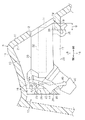


Classifications
-
- B—PERFORMING OPERATIONS; TRANSPORTING
- B60—VEHICLES IN GENERAL
- B60S—SERVICING, CLEANING, REPAIRING, SUPPORTING, LIFTING, OR MANOEUVRING OF VEHICLES, NOT OTHERWISE PROVIDED FOR
- B60S1/00—Cleaning of vehicles
- B60S1/02—Cleaning windscreens, windows or optical devices
- B60S1/46—Cleaning windscreens, windows or optical devices using liquid; Windscreen washers
- B60S1/48—Liquid supply therefor
- B60S1/52—Arrangement of nozzles; Liquid spreading means
Landscapes
- Engineering & Computer Science (AREA)
- Water Supply & Treatment (AREA)
- Mechanical Engineering (AREA)
- Body Structure For Vehicles (AREA)
Description
本発明は、車両のフロントガラス(ウインドシールドガラス)に洗浄液を噴射するためのウォッシャノズルを該フロントガラスの下部に配設されるカウルパネルに取り付ける、その取付構造に関するものである。 The present invention relates to a mounting structure in which a washer nozzle for injecting a cleaning liquid onto a windshield (windshield glass) of a vehicle is attached to a cowl panel disposed under the windshield.
この種のウォッシャノズル取付構造は、例えば特許文献1にて開示されている。この特許文献1では、車両のカウルパネル(文献中、カウルトップガーニッシュ)に円筒状の隆起部が設けられており、該隆起部の先端にはカウルパネルの外側からウォッシャノズルが装着されている。
This type of washer nozzle mounting structure is disclosed in
ウォッシャノズルは、カウルパネルの内側に延びるホース装着部(文献中、ホース連結部)を有している。ホース装着部には、ウォッシャタンクから延びるホースが装着される。そして、ウォッシャポンプの作動により、ホースを通じてウォッシャタンクから洗浄液がウォッシャノズルに供給されることで、該ウォッシャノズルからフロントガラスに洗浄液が噴射されるようになっている。 The washer nozzle has a hose attachment part (in the literature, a hose connection part) extending inside the cowl panel. A hose extending from the washer tank is attached to the hose attachment portion. Then, by operating the washer pump, the cleaning liquid is supplied from the washer tank to the washer nozzle through the hose, so that the cleaning liquid is jetted from the washer nozzle onto the windshield.
本発明の目的は、カウルパネルの内側に取り付けられるウォッシャノズルのカウルパネルの開口部からの突出を防止するとともに、ウォッシャノズルをカウルパネルに対してがたつきなく装着することができるウォッシャノズル取付構造を提供することにある。 An object of the present invention is to provide a washer nozzle mounting structure capable of preventing a washer nozzle mounted on the inside of a cowl panel from protruding from the opening of the cowl panel and mounting the washer nozzle on the cowl panel without rattling. Is to provide.
上記目的を達成するために、請求項1に記載の発明は、車両のフロントガラスの下部に配設されるカウルパネルの内側に、前記フロントガラスの払拭面に向かって洗浄液を噴射するためのウォッシャノズルを取り付ける、その取付構造であって、前記カウルパネルは、内側において上方に凹設した形状をなす凹設部を有しており、該凹設部において前記フロントガラスと対向するガラス側壁部に前記ウォッシャノズルの後部が装着される開口部を有するとともに、前記凹設部内に前記ウォッシャノズルの前部が装着される装着壁部を有し、更に、前記ガラス側壁部における前記開口部の縁部に装着片が前記装着壁部側に突出形成され、前記ウォッシャノズルは、前記開口部に装着される後部に前記カウルパネルの外側に臨むように前記洗浄液を噴射する噴射孔を有し、更に、前記ウォッシャノズルの後部に前記装着片における上下方向の一側面と当接する後側当接部が設けられ、そのウォッシャノズルの後部に前記装着片における上下方向の他側面と当接するとともにその装着片の他側面を弾性力にて押圧する後側弾性片が設けられ、そのウォッシャノズルの後部がその後側弾性片と前記後側当接部とで前記装着片を挟み込むことで装着片に対して装着され、前記ウォッシャノズルの前部に前側弾性片が設けられるとともに、前記ウォッシャノズルの後部に前記装着片における前記装着壁部側の端部に当接することで後部の前記開口部からの突出を規制する第1規制当接部が設けられ、前記前側弾性片の弾性力によりその前側弾性片が前記装着壁部を押圧することで、前記第1規制当接部の前記装着片への当接方向に弾性力を付与して第1規制当接部を前記装着片の端部に押圧させることをその要旨とする。 In order to achieve the above object, a first aspect of the present invention provides a washer for injecting a cleaning liquid toward a wiping surface of the windshield inside a cowl panel disposed at a lower portion of a windshield of a vehicle. A mounting structure for mounting a nozzle, wherein the cowl panel has a recessed portion having a shape recessed upward on the inside, and a glass side wall portion facing the windshield in the recessed portion. The rear portion of the washer nozzle has an opening to be attached, the recessed portion has an attachment wall portion to which the front portion of the washer nozzle is attached, and the edge portion of the opening in the glass side wall portion A mounting piece projecting toward the mounting wall, and the washer nozzle is disposed at the rear portion mounted on the opening and faces the outside of the cowl panel. A rear abutting portion that abuts on one side of the mounting piece in the vertical direction at a rear portion of the washer nozzle, and a vertical portion of the mounting piece in the rear direction of the washer nozzle; A rear elastic piece that abuts against the other side surface and presses the other side surface of the mounting piece with an elastic force is provided, and the rear part of the washer nozzle has the rear elastic piece and the rear contact part to The front elastic piece is provided at the front part of the washer nozzle by being sandwiched, and the rear part is brought into contact with the end of the attachment piece on the mounting wall part at the rear part of the washer nozzle A first restricting contact portion for restricting the protrusion of the first elastic piece from the opening, and the front elastic piece presses the mounting wall portion by the elastic force of the front elastic piece, whereby the first restriction is provided. That to press the first regulatory contact portion by applying an elastic force to the contact direction to the mounting piece of the contact portion to an end portion of the mounting piece and the gist thereof.
この発明によれば、ウォッシャノズルには後部の開口部からの突出を規制すべく装着片と当接する第1規制当接部が設けられ、前側弾性片は第1規制当接部の当接方向に弾性力を付与する。つまり、第1規制当接部が装着片に当接することでウォッシャノズルの開口部からの突出が防止されるとともに、前側弾性片により第1規制当接部が装着片に押圧されることから、ウォッシャノズルがカウルパネルに対してがたつきなく装着される。また、ウォッシャノズルの後部には後側弾性片が設けられ、前部には前側弾性片が設けられるため、ウォッシャノズルがカウルパネルに対してがたつきなく装着される。 According to the present invention, the washer nozzle is provided with the first restriction contact portion that contacts the mounting piece so as to restrict the protrusion from the rear opening, and the front elastic piece is in the contact direction of the first restriction contact portion. An elastic force is given to. That is, the first restriction contact portion abuts against the mounting piece to prevent the washer nozzle from protruding from the opening, and the first elastic contact piece presses the first restriction contact portion against the attachment piece. The washer nozzle is attached to the cowl panel without rattling. Further, since the rear elastic piece is provided at the rear part of the washer nozzle and the front elastic piece is provided at the front part, the washer nozzle is attached to the cowl panel without rattling.
請求項2に記載の発明は、請求項1に記載のウォッシャノズル取付構造において、前記カウルパネルは、前記凹設部内に前記ウォッシャノズルに向けて突出形成される移動規制部を有し、前記ウォッシャノズルの上壁面には、ウォッシャノズルが前方に移動したときに前記移動規制部の後側部と当接することで、ウォッシャノズルのそれ以上の前方側への移動を規制する第2規制当接部が設けられていることをその要旨とする。 According to a second aspect of the present invention, in the washer nozzle mounting structure according to the first aspect, the cowl panel includes a movement restricting portion that is formed to protrude toward the washer nozzle in the recessed portion, and the washer A second regulating contact portion that regulates further forward movement of the washer nozzle by contacting the rear side portion of the movement regulating portion when the washer nozzle moves forward, on the upper wall surface of the nozzle The gist of this is that it is provided.
この発明によれば、ウォッシャノズルのカウルパネルへの取付状態において開口部からウォッシャノズルを押し込む方向の外力が作用しても、第2規制当接部が移動規制部と当接することでウォッシャノズルの同押し込み方向への移動が規制される。 According to this invention, even if an external force in the direction of pushing the washer nozzle from the opening acts when the washer nozzle is attached to the cowl panel, the second restricting contact portion comes into contact with the movement restricting portion, thereby Movement in the pushing direction is restricted.
請求項3に記載の発明は、請求項2に記載のウォッシャノズル取付構造において、前記後側当接部は、前記第2規制当接部が前記移動規制部の後側部と当接するときに前記装着片の前記一側面と当接することをその要旨とする。 According to a third aspect of the present invention, in the washer nozzle mounting structure according to the second aspect, the rear contact portion is configured such that the second restriction contact portion contacts the rear side portion of the movement restriction portion. The gist is to contact the one side surface of the mounting piece.
この発明によれば、ウォッシャノズルは、前方(この場合、開口部方向と反対方向)への移動が規制されたときでも後側当接部が装着片と当接するので、ウォッシャノズルの取付姿勢が常に安定する。 According to the present invention, the washer nozzle is in contact with the mounting piece even when the forward movement (in this case, the direction opposite to the opening direction) is restricted. Always stable.
請求項4に記載の発明は、請求項1に記載のウォッシャノズル取付構造において、前記ウォッシャノズルの前部には、前記装着壁部の側部と前後方向において対向し、ウォッシャノズルが前方に移動したときにその装着壁部の側部に当接することで、ウォッシャノズルのそれ以上の前方側への移動を規制する当接規制部が設けられていることをその要旨とする。 According to a fourth aspect of the present invention, in the washer nozzle mounting structure according to the first aspect, the front portion of the washer nozzle faces the side portion of the mounting wall portion in the front-rear direction, and the washer nozzle moves forward. The gist of the invention is that a contact restricting portion is provided that restricts the further movement of the washer nozzle forward by contacting the side portion of the mounting wall portion.
請求項5に記載の発明は、請求項4に記載のウォッシャノズル取付構造において、前記後側当接部は、前記当接規制部が前記装着壁部の側部と当接するときに前記装着片の前記一側面と当接することをその要旨とする。 According to a fifth aspect of the present invention, in the washer nozzle mounting structure according to the fourth aspect, the rear contact portion is configured such that the mounting piece is in contact with the side portion of the mounting wall portion. The gist of this is to abut against the one side surface.
本発明によれば、カウルパネルの内側に取り付けられるウォッシャノズルのカウルパネルの開口部からの突出を防止するとともに、ウォッシャノズルをカウルパネルに対してがたつきなく装着することができるウォッシャノズル取付構造を提供することができる。 According to the present invention, a washer nozzle mounting structure capable of preventing a washer nozzle mounted on the inside of a cowl panel from protruding from the opening of the cowl panel and mounting the washer nozzle on the cowl panel without rattling. Can be provided.
(第1の実施の形態)
以下、本発明を具体化した第1の実施の形態を図面に従って説明する。
図1及び図2に示すように、車両のフロントガラス1の下部とボンネット2との間には、車幅方向に長い形状をなす樹脂製のカウルパネル3が配設されている。カウルパネル3には、対をなす車両用ワイパ4を駆動するためのピボット軸(図示略)が挿通されている。
(First embodiment)
Hereinafter, a first embodiment of the present invention will be described with reference to the drawings.
As shown in FIGS. 1 and 2, a
カウルパネル3は、上方に凸となるように屈曲された凸状部10が長手方向に連続して設けられ、該凸状部10はフロントガラス1に対向するガラス側壁部11を有している。ガラス側壁部11には、カウルパネル3の長手方向(車幅方向)の所定の2箇所に、それぞれ略矩形状の開口部12が設けられている。各開口部12は、カウルパネル3(凸状部10)の内側に配置されるウォッシャノズル30からの洗浄液Wの噴射を可能としている。
The
カウルパネル3の凸状部10の内側には、上方に凹設した形状をなす凹設部13が設けられている。凹設部13には、各開口部12が設けられる部分において、それぞれウォッシャノズル30を装着するためのノズル装着部15が設けられている。
On the inner side of the
図3及び図5に示すように、ノズル装着部15は、前記ガラス側壁部11と、該ガラス側壁部11と対向するようにカウルパネル3の内側面から下方に板状に延出される装着壁部16と、該装着壁部16の両側とガラス側壁部11とを連結すべく板状に延出される連結壁部17,18とを有し、各壁部11,16〜18にて四方が囲まれた四角筒状をなしている。
As shown in FIGS. 3 and 5, the
ガラス側壁部11における開口部12の下縁部には、両側が各連結壁部17,18の下端部と接続されつつ装着壁部16側に板状に突出する装着片19が形成されている。装着片19の装着壁部16側の略矩形状をなす開口は挿入口20となっており、該挿入口20には下方から各壁部11,16〜18で囲まれた収容凹部21内にウォッシャノズル30が挿入され装着される。
A
図3及び図4に示すように、ウォッシャノズル30は、樹脂製であって略直方体形状に形成されている。尚、ウォッシャノズル30は、前記開口部12側に装着されるのを後部とし、前記装着壁部16に装着されるのを前部とする。ウォッシャノズル30は、その前部が車両前方側に、後部が車両後方側に向けて装着される。
As shown in FIGS. 3 and 4, the
ウォッシャノズル30の後部から説明すると、ウォッシャノズル30の後面中央には、矩形状に開口するチップ嵌挿孔31が形成されている。チップ嵌挿孔31は、ウォッシャノズル30の前側に延びている。チップ嵌挿孔31には、略直方体形状をなすノズルチップ(流体素子)32が着脱可能に装着される。
If it demonstrates from the rear part of the
ノズルチップ32は、後端部(チップ嵌挿孔31の開口側)に洗浄液Wを噴射する噴射孔33が形成されている。ノズルチップ32は、噴射孔33に通じる主流路(図示略)と、該主流路の下流側から上流側に連通されるフィードバック流路(図示略)とを有し、洗浄液Wをフィードバック流路を介して主流路に戻すことで該主流路内の洗浄液Wを自励発振させ、噴射孔33からフロントガラス1の払拭面1aに対する洗浄液Wの噴射を拡散噴射とするものである(図1参照)。このようなノズルチップ32は例えば車種毎に設けられ、ウォッシャノズル30のボディを複数の車種間で共用可能としている。
The
ウォッシャノズル30の後側下縁部には、凸状の後側当接部34が形成されている。後側当接部34は、ウォッシャノズル30の後側下縁部の幅方向に連続して設けられている。この後側当接部34は、前記開口部12下縁に設けた装着片19の上面と当接する。
A convex
また、ウォッシャノズル30の後側下面には、後側当接部34の若干前方側において後側弾性片35が設けられている。後側弾性片35は、ウォッシャノズル30より幅狭に形成されており、該ウォッシャノズル30の幅方向中央に設けられている。後側弾性片35は、先端部が前記開口部12下縁に設けた装着片19の下面と当接する。この場合、後側弾性片35は装着片19の下面を自身の弾性力にて押圧し、これに伴って後側当接部34の当接方向に弾性力を付与して、後側当接部34を該装着片19の上面に押圧させる。ウォッシャノズル30の後部は、後側弾性片35と後側当接部34とで装着片19を挟み込むことで装着片19に対して装着される。
In addition, a rear
また、後側弾性片35の基端部には、前記装着片19の先端面に当接する規制当接部(第1規制当接部)36が設けられている。規制当接部36は前記装着片19の先端面に当接することで、ウォッシャノズル30の開口部12からの突出が規制(防止)される。
In addition, a restriction contact portion (first restriction contact portion) 36 that contacts the distal end surface of the mounting
一方、ウォッシャノズル30の前部下面における幅方向中央には、該ウォッシャノズル30の前方斜め下方に向けて円筒状に延びるホース装着部40が設けられている。ホース装着部40には、車両に搭載されるウォッシャタンク(図示略)から延びるゴム製のホース41が装着される(図2参照)。ホース装着部40内の流路は、前記ノズルチップ32の主流路の基端部(噴射孔33と反対側)に繋がっている。そして、ウォッシャポンプ(図示略)の作動により、ホース41を通じてウォッシャタンクから洗浄液Wがウォッシャノズル30(ノズルチップ32)に供給されることで、該ウォッシャノズル30の噴射孔33から払拭面1aに対して洗浄液Wの拡散噴射がなされる。
On the other hand, at the center in the width direction on the lower surface of the front portion of the
ウォッシャノズル30のホース装着部40の上部(幅方向中央)には、板状の前側当接部42が設けられている。ここで、前記装着壁部16には、前側当接部42の先端部が当接する壁側当接部25が設けられている。壁側当接部25は、その当接面が下方を向いている。前側当接部42の先端部はその壁側当接部25に当接することで、ウォッシャノズル30の前部がそれ以上上方に移動することが規制される。
A plate-like
前側当接部42には、装着壁部16の側面部27と前後方向において対向し、ウォッシャノズル30が前方に移動した際に当接する当接規制部42aが設けられている。この当接規制部42aは、図3に示すウォッシャノズル30の正規の姿勢にて保持されている場合では、装着壁部16の側面部27に対して前後方向に隙間Tが設定されている。この隙間Tは、前記装着片19の先端面と後側当接部34との間隔αより小さく設定されている。つまり、ウォッシャノズル30が前方に移動しようとした場合、後側当接部34が装着片19の上面から脱落するよりも前に当接規制部42aが装着壁部16の側面部27に当接し、ウォッシャノズル30のそれ以上前方への移動が規制されるようになっている。
The
また、ウォッシャノズル30の前部上面には、幅方向の前側当接部42及びホース装着部40の両側に、それぞれ前側弾性片43が設けられている。各前側弾性片43は、前方斜め下方に向けて延出されている。
Further, on the upper surface of the front portion of the
前側弾性片43の略中央には、ウォッシャノズル30の前方に向けて略三角形状に突出する係止突起44が形成されている。ここで、前記装着壁部16には、幅方向の壁側当接部25の両側に、それぞれ矩形状の係止孔26が形成されている。この係止孔26内に係止突起44が挿入されて係止孔26の下側縁部26aと係止可能状態となることで、ウォッシャノズル30の前部の下方への移動を規制し、ウォッシャノズル30のノズル装着部15からの脱落が防止される。
A locking
前側弾性片43の係止突起44よりも下側には、該係止突起44と連続して当接斜面45が形成されている。当接斜面45は前方斜め下方に向く平面をなしており、前側当接部42が壁側当接部25に当接した状態で係止孔26の下側縁部26aと当接する。当接斜面45は、前側弾性片43自身の弾性力により、係止孔26の下側縁部26aに押圧される。この場合、当接斜面45が係止孔26の下側縁部26aを押圧することで、前側当接部42の当接方向に弾性力を付与して前側当接部42を壁側当接部25に押圧させるとともに、前記規制当接部36の当接方向にも弾性力を付与して規制当接部36を装着片19の先端面に押圧させる。
A
前側弾性片43の先端部は、操作部46となっている。操作部46は、前側弾性片43の弾性力に抗してウォッシャノズル30の後方に傾動させて係止突起44を係止孔26から抜き、装着壁部16に対するウォッシャノズル30の前部の装着を解除するために設けられている。これにより、ウォッシャノズル30のノズル装着部15からの取り外しが可能となっている。
A front end portion of the front
このような構成のウォッシャノズル30をノズル装着部15(収容凹部21内)に装着する際(図3参照)、先ず、挿入口20に向けてウォッシャノズル30の後部を斜め上方(ガラス側壁部11の開口部12側)を向くようにし、後側弾性片35と後側当接部34とが装着片19を挟み込むように該装着片19に引っ掛けられる。
When the
次いで、装着片19に引っ掛けられた例えば後側弾性片35の接触部分が支点となってウォッシャノズル30の前端が上方に回動され、該ウォッシャノズル30が挿入口20から収容凹部21内に挿入される。この場合、前側弾性片43の係止突起44が装着壁部16の下端から内側面に当接しながら係止孔26内に挿入されるまで、ウォッシャノズル30の前部が挿入口20内に挿入される。
Next, the front end of the
次いで、前側弾性片43の係止突起44が装着壁部16の係止孔26内に挿入されると、前側弾性片43の弾性復帰し、該係止突起44と連続するように設けられる当接斜面45が係止孔26の下側縁部26aに当接する。この場合、前側弾性片43の弾性力にて当接斜面45が係止孔26の下側縁部26aを押圧することで、ウォッシャノズル30の前部が上方に押し上げられ、前側当接部42が壁側当接部25に当接する。
Next, when the locking
また、前側当接部42が壁側当接部25に当接した状態となっても、前側弾性片43の弾性力により当接斜面45が係止孔26の下側縁部26aを押圧するようになっており、これにより前側当接部42が壁側当接部25を押圧するとともに、規制当接部36が装着片19の先端面に押圧される。こうしてウォッシャノズル30がノズル装着部15(収容凹部21)内にがたつきなく装着される。
Even if the
そして、ウォッシャノズル30が装着されると、該ウォッシャノズル30のホース装着部40にウォッシャタンク側から延びるゴム製のホース41が装着される(図2参照)。ホース41は、その内径を広げつつホース装着部40に装着される。このとき、ホース装着部40にはホース41の装着方向(後方斜め上方)等に比較的大きな装着力が作用し、ウォッシャノズル30の前部を上方に移動させようとする。場合によっては、ウォッシャノズル30の前部を上方に、ウォッシャノズル30の後部を下方に移動させようとする。このような場合、ウォッシャノズル30の前部では前側当接部42が壁側当接部25に当接し、後部では後側当接部34が装着片19の上面に当接しているため、ウォッシャノズル30の前部が上方に、ウォッシャノズル30の後部が下方に移動することが防止される。
When the
つまり、ホース41の装着の際にウォッシャノズル30の装着位置がずれることが防止されるため、その中でもウォッシャノズル30の仰角のずれが防止されることで、フロントガラス1の払拭面1aにおける洗浄液Wの着水位置が所望の位置から大きくずれてしまうことが未然に防止されるようになっている。逆に、ホース41のホース装着部40への装着力が開放され、ホース41の重量等によりウォッシャノズル30に上記装着方向と逆方向の力が一時的に作用しても、ウォッシャノズル30は前側弾性片43の上記弾性力により姿勢が自己補正されて正規の姿勢に保持される。
That is, since the mounting position of the
また、ウォッシャノズル30の装着後、高圧洗車や洗車ブラシ等により開口部12側からウォッシャノズル30が前側弾性片43の弾性力に抗して前方に押された場合、後側当接部34が装着片19の上面から外れるよりも前に当接規制部42aが装着壁部16の側面部27に当接するように隙間Tが設定されているため、このような場合のウォッシャノズル30の脱落も防止されている。
Further, after the
次に、本実施の形態の特徴的な作用効果を記載する。
(1)カウルパネル3のガラス側壁部11にはウォッシャノズル30の後部が装着される開口部12が設けられ、カウルパネル3内側の凹設部13内にはウォッシャノズル30の前部が装着される装着壁部16が設けられている。これに対し、ウォッシャノズル30は後部に噴射孔33が設けられており、前部において下方に延びるホース装着部40が設けられている。このようなウォッシャノズル30は、後部において下方への移動を規制すべく開口部12下縁の装着片19の上面と当接する後側当接部34が設けられ、前部において上方への移動を規制すべく装着壁部16の壁側当接部25と当接する前側当接部42が設けられている。ここで、ホース装着部40に車体側から延びるホース41が装着される際、該ホース装着部40にはホース41の装着方向等に比較的大きな装着力が作用し、ウォッシャノズル30の前部を上方に移動させようとし、場合によってはウォッシャノズル30の前部を上方に、後部を下方に移動させようとする。このような場合、ウォッシャノズル30の前部では前側当接部42が壁側当接部25に当接し、後部では後側当接部34が装着片19の上面に当接しているため、ウォッシャノズル30の前部が上方に、後部が下方に移動することを防止することができる。つまり、ホース41の装着の際にウォッシャノズル30の装着位置がずれることを防止できるため、その中でもウォッシャノズル30の仰角のずれを防止できることで、フロントガラス1の払拭面1aにおける洗浄液Wの着水位置が所望の位置から大きくずれてしまうことを未然に防止することができる。
Next, characteristic actions and effects of the present embodiment will be described.
(1) The glass
(2)ウォッシャノズル30の後部には後側当接部34の当接方向に弾性力を付与する後側弾性片35が設けられ、前部には前側当接部42の当接方向に弾性力を付与する前側弾性片43が設けられている。つまり、後側弾性片35により後側当接部34が装着片19の上面に押圧され、前側弾性片43により前側当接部42が壁側当接部25に押圧されるため、ウォッシャノズル30をカウルパネル3(ノズル装着部15)に対してがたつきなく装着することができ、装着位置のずれをより確実に防止することができる。
(2) A rear
(3)ホース装着部40はウォッシャノズル30の幅方向中央に配置され、対で設けられる前側弾性片43が幅方向においてホース装着部40の両側に設けられている。つまり、幅方向中央に配置されるホース装着部40からホース41装着時の装着力がウォッシャノズル30に幅方向においてバランスよく作用し、しかもホース装着部40の両側の各前側弾性片43にて前側当接部42に幅方向においてバランスよく弾性力が付与できる。そのため、ウォッシャノズル30を安定して支持でき、該ウォッシャノズル30の装着位置のずれをより確実に防止することができる。
(3) The
(4)ウォッシャノズル30には後部の開口部12からの突出を規制すべく装着片19の先端面と当接する規制当接部36が設けられており、前側弾性片43は規制当接部36の当接方向にも弾性力を付与する。つまり、規制当接部36が装着片19の先端面に当接することでウォッシャノズル30の開口部12からの突出を防止しつつ、前側弾性片43により規制当接部36が装着片19の先端面に押圧されることから、ウォッシャノズル30をカウルパネル3(ノズル装着部15)に対してがたつきなく装着することができる。
(4) The
また、規制当接部36が後側弾性片35に一体に設けられるため、ウォッシャノズル30の形状の簡素化に貢献できる。また、前側当接部42の当接方向に弾性力を付与する前側弾性片43にて規制当接部36の当接方向にも弾性力を付与する構成としているため、弾性片の共通化が図られ、これによってもウォッシャノズル30の形状の簡素化に貢献できる。
Further, since the restricting
(5)カウルパネル3には、ウォッシャノズル30の幅方向両側においてガラス側壁部11と装着壁部16とをそれぞれ連結する連結壁部17,18が設けられている。つまり、ノズル装着部15の四方が連続する壁部にて囲まれるため、該ノズル装着部15の剛性が高くなる。そのため、例えばノズル装着部15に外力が作用しても該ノズル装着部15が変形し難くなるため、変形による相互の係止状態が解除されることを防止でき、これによりウォッシャノズル30の脱落を防止することができる。
(5) The
(第2の実施の形態)
以下、本発明を具体化した第2の実施の形態を図面に従って説明する。尚、本実施の形態のウォッシャノズル50では、前部及び後部の装着部分の構成が変更されている。これに伴い、カウルパネル3の凹設部13におけるウォッシャノズル50を装着するための構成も変更されている。従って、以下には、これらの部分を中心に説明し、前記第1の実施の形態と同様の構成ついては同一の符号を付して説明を省略する。
(Second Embodiment)
Hereinafter, a second embodiment of the present invention will be described with reference to the drawings. In addition, in the
先ず、ウォッシャノズル50の前部の装着部分について、図6及び図8に示すように、カウルパネル3(凹設部13)の内側面には、該内側面から下方に板状に延出されウォッシャノズル50の前部を装着させるための装着壁部60と、ウォッシャノズル50の上壁面50aに向けて垂下するように板状に突出形成される移動規制部61とが設けられている。装着壁部60は、その幅方向両側とガラス側壁部11とを連結すべく板状に延出される連結壁部62,63とを有し、各壁部11,60,62,63にて四方が囲まれた四角筒状をなしている。
First, as shown in FIGS. 6 and 8, the front mounting portion of the
また、装着壁部60には、幅方向中央に下端から切り欠かれウォッシャノズル50のホース装着部40に装着されるホース41との干渉を防止する切欠部64が設けられ、該切欠部64の両側においては、ウォッシャノズル50の各前側弾性片43と係止すべく延出される係止部65がそれぞれ設けられている。そして、ウォッシャノズル50は、前側弾性片43に設けた当接斜面45が係止部65に当接するように装着される。このとき、前側弾性片43自身の弾性力により、後述する前側当接部51の当接方向に弾性力が付与されて前側当接部51が移動規制部61の下面に押圧されるとともに、後述する規制当接部53の当接方向にも弾性力が付与されて規制当接部53が装着片19の先端面に押圧されるようにウォッシャノズル50が装着される。
Further, the mounting
移動規制部61は、その下端がカウルパネル3に設けた開口部12の上縁部と略等しい位置まで下方に向けて延出されている。また、移動規制部61は、幅方向においては一方の連結壁部62の内側面から他方の連結壁部63寄りの所定位置まで延出されている。この移動規制部61は、幅方向中央から所定間隔を有する一対の連結壁部66,67が前記連結壁部62,63と平行に延びてガラス側壁部11と連結し、所定の剛性が確保されている。そして、このような移動規制部61には、その下面にウォッシャノズル50の上壁面50aの前側に設けられる前側当接部51が当接するとともに、該規制部61の後側面にその前側当接部51より若干後方に設けられる規制当接部(第2規制当接部)52が当接する。
The lower end of the
図7に示すように、ウォッシャノズル50の上壁面50aに立設された前側当接部51は、断面半円状をなしウォッシャノズル50の幅方向全体に亘り連続して設けられている。つまり、万一、ウォッシャノズル50が幅方向にずれて装着された場合であっても、前側当接部51が移動規制部61の下面に確実に当接するようになっている。
As shown in FIG. 7, the
また、ウォッシャノズル50の上壁面50aにおいて、前側当接部51の若干後方の幅方向中央に規制当接部52が立設されている。規制当接部52は、側方視略台形状で前面(移動規制部61の後側面と対向する面)が垂直面をなす四角柱状に形成されている。この規制当接部52は、通常、図6の実線にて示すウォッシャノズル50の装着位置では、上記したように前側弾性片43自身の弾性力にて後述の規制当接部53が装着片19の先端面に当接することで、移動規制部61から離間して配置される。これに対し、カウルパネル3の開口部12からウォッシャノズル50を前方側に押し込むような外力が作用すると、前側弾性片43の弾性力に抗して規制当接部52の前面が移動規制部61の後側面に当接する図6の2点鎖線にて示す位置までの移動は許容され、それ以上押し込み方向(前方)への移動が規制されるようになっている。このとき、ウォッシャノズル50が図6の2点鎖線にて示す最大押込位置まで押し込まれても、前側当接部51が移動規制部61の下面と当接する状態が維持されるようにもなっている。
In addition, on the upper wall surface 50 a of the
一方、ウォッシャノズル50の後部の装着部分について、図6及び図7に示すように、規制当接部(第1規制当接部)53と、後側弾性片54とが個別に設けられている。規制当接部53は、ウォッシャノズル50の後側下縁部に設けた後側当接部34の若干前方側に、断面長方形状をなしウォッシャノズル50の幅方向全体に亘り連続して設けられている。この規制当接部53は、通常、図6の実線にて示すウォッシャノズル50の装着位置では、前側弾性片43自身の弾性力にて装着片19の先端面に当接(押圧)し、ウォッシャノズル50はその取付姿勢が維持される。
On the other hand, as shown in FIGS. 6 and 7, a restricting contact portion (first restricting contact portion) 53 and a rear
後側弾性片54は、その規制当接部53よりも更に前方側においてウォッシャノズル50よりも若干幅狭に形成されており、該ウォッシャノズル50の幅方向中央に設けられている。後側弾性片54は、先端部が後側当接部34の近傍位置となるまで後方に向けて延出され、先端部に設けた凸状の当接部55がカウルパネル3の装着片19の下面と当接する。この場合、後側弾性片54(当接部55)は装着片19の下面を自身の弾性力にて押圧し、これに伴って後側当接部34を該装着片19の上面に押圧させる。しかも、後側弾性片54先端の当接部55は、後側当接部34と上下方向(垂直方向)で対向する位置に設けられているため、前側弾性片43の弾性力がウォッシャノズル50を側方から見て回転させる方向に作用しないようになっている。
The rear
また、上記したようにカウルパネル3の開口部12からウォッシャノズル50を前方側に押し込むような外力が作用し、前記規制当接部52の前面が移動規制部61の後側面に当接する図6の2点鎖線にて示す最大押込位置まで押し込まれた場合、規制当接部53が装着片19の先端面から離間するが、前記後側当接部34及び後側弾性片54の当接部55は装着片19の上面及び下面と当接する状態が維持されるようになっている。
Further, as described above, an external force that pushes the
次に、上記第1の実施の形態と同様の作用効果(1)〜(5)に加え、本実施の形態の特徴的な作用効果を記載する。
(1)本実施の形態においても、ウォッシャノズル50の前部では前側当接部51が凹設部13に設けた移動規制部61の下面に当接し、後部では後側当接部34が装着片19の上面に当接しているため、ウォッシャノズル50の前部が上方に、後部が下方に移動することを防止することができる。つまり、ホース41の装着の際にウォッシャノズル50の装着位置がずれることを防止できるため、その中でもウォッシャノズル50の仰角のずれを防止できることで、フロントガラス1の払拭面1aにおける洗浄液Wの着水位置が所望の位置から大きくずれてしまうことを未然に防止することができる。
Next, in addition to the same operational effects (1) to (5) as in the first embodiment, the characteristic operational effects of the present embodiment will be described.
(1) Also in the present embodiment, the
(2)本実施の形態においても、後側弾性片54により後側当接部34が装着片19の上面に押圧され、前側弾性片43により前側当接部51が移動規制部61の下面に押圧されるため、ウォッシャノズル50をカウルパネル3(ノズル装着部15)に対してがたつきなく、しかも姿勢が自己調整されて装着することができ、装着位置のずれをより確実に防止することができる。
(2) Also in the present embodiment, the
(3)本実施の形態においても、幅方向中央に配置されるホース装着部40からホース41装着時の装着力がウォッシャノズル50に幅方向においてバランスよく作用し、しかもホース装着部40の両側の各前側弾性片43にて前側当接部51に幅方向においてバランスよく弾性力が付与できる。そのため、ウォッシャノズル50を安定して支持でき、該ウォッシャノズル50の装着位置のずれをより確実に防止することができる。
(3) Also in the present embodiment, the mounting force at the time of mounting the
(4)本実施の形態においても、規制当接部53が装着片19の先端面に当接することでウォッシャノズル50の開口部12からの突出を防止しつつ、前側弾性片43により規制当接部53が装着片19の先端面に押圧されることから、ウォッシャノズル50をカウルパネル3(ノズル装着部15)に対してがたつきなく装着することができる。
(4) Also in the present embodiment, the
(5)本実施の形態においても、ノズル装着部15の四方が連続する壁部11,60,62,63にて囲まれるため、樹脂製のカウルパネル3における該ノズル装着部15の剛性が高くなる。そのため、例えばノズル装着部15に外力が作用しても該ノズル装着部15が変形し難くなるため、変形による相互の係止状態が解除されることを防止でき、これによりウォッシャノズル50の脱落を防止することができる。
(5) Also in this embodiment, since the
(6)本実施の形態では更に、カウルパネル3に設けた凹設部13の内部に、突出形成されてウォッシャノズル50の前側当接部51と当接する移動規制部61が設けられている。そのため、前側当接部51と移動規制部61との当接位置を比較的大きな自由度をもって設定することができる。
(6) In the present embodiment, a
(7)本実施の形態では更に、ウォッシャノズル50の上壁面50aに、移動規制部61と当接する前側当接部51が設けられるとともに、移動規制部61の後側面と当接してウォッシャノズル50の前方側への移動を規制する規制当接部52が設けられている。そのため、ウォッシャノズル50のカウルパネル3への取付状態において開口部12からウォッシャノズル50を押し込む方向の外力が作用しても、規制当接部52が移動規制部61と当接することでウォッシャノズル50の同押し込み方向への移動を規制することができる。
(7) In the present embodiment, the
(8)本実施の形態では更に、ウォッシャノズル50の前部の規制当接部53が開口部12下縁の装着片19と当接するときに前側当接部51が移動規制部61の下面と当接するとともに、規制当接部52が移動規制部61の後側面と当接するときに後側当接部34が開口部12下縁の装着片19と当接する構成とした。そのため、ウォッシャノズル50は、カウルパネル3の凹設部13内で前後方向に移動しても、各規制当接部52,53によってその移動が規制され、後方(この場合、開口部12方向)への移動が規制されたときでも前側当接部51は移動規制部61に当接し、前方(この場合、開口部12方向と反対方向)への移動が規制されたときでも後側当接部34は開口部12下縁の装着片19と当接するので、ウォッシャノズル50の取付姿勢を常に安定させることができるとともに、ウォッシャノズル50のカウルパネル3からの不用意な脱落を防止できる。
(8) Further, in the present embodiment, when the
尚、本発明の実施の形態は、以下のように変更してもよい。
・上記各実施の形態では、開口部12下縁に設けた板状の装着片19にウォッシャノズル30,50の後部を装着するようにしたが、該後部を装着する部位の形状はこれに限定されず、例えば凹部や孔等に変更してもよい。また、この後部を装着する部位の位置を適宜変更してもよく、例えば開口部12の上縁や側縁等に変更してもよい。一方、ウォッシャノズル30,50側においても同様に後側当接部34や後側弾性片35,54の形状や設ける位置を適宜変更してもよい。
The embodiment of the present invention may be modified as follows.
In each of the above embodiments, the rear part of the
・上記第1の実施の形態では、壁側当接部25の下面に前側当接部42を当接させて装着壁部16に設けた係止孔26にウォッシャノズル30の前部を装着し、上記第2の実施の形態では、移動規制部61の下面に前側当接部51を当接させて装着壁部60に設けた係止部65にウォッシャノズル50の前部を装着したが、該前部を装着する部位の形状及び位置はこれに限定されず、適宜変更してもよい。一方、ウォッシャノズル30,50側においても同様に前側当接部42,51や前側弾性片43の形状や設ける位置を適宜変更してもよい。例えば、前側当接部42,51を1つではなく複数設けてもよく、前側弾性片43を対ではなく1つとしてもよい。
In the first embodiment, the front part of the
・上記各実施の形態では、前側当接部42,51の当接方向に弾性力を付与する前側弾性片43にて規制当接部36,53の当接方向にも弾性力を付与する構成としたが、それぞれに弾性力を付与する弾性片を別々に設けてもよい。
In each of the above embodiments, the front
・上記各実施の形態では、ノズル装着部15を、ガラス側壁部11と装着壁部16,60とこれらを連結する連結壁部17,18,62,63とで四方を連続する壁部にて囲むように構成したが、この構成に限らず、例えば連結壁部17,18,62,63のいずれかを省略、若しくは両方を省略してもよい。
In each of the above embodiments, the
・上記各実施の形態では、拡散噴射を行うためのノズルチップ32を内装したウォッシャノズル30,50を用いたが、ノズルチップ32を用いずウォッシャノズル自体に噴射孔を有するものを用いてもよい。
In each of the above-described embodiments, the
・ところで、特許文献1のウォッシャノズルのホース装着部にホース(ゴム製)を装着する際、ホースの内径を広げつつ該ホースをホース装着部に装着するため、比較的大きな装着力が必要である。そのため、ホース装着の際にウォッシャノズルの装着位置がずれ、特にウォッシャノズルの仰角がずれてしまうと、フロントガラス上の洗浄液の着水位置が所望の位置から大きくずれてしまうという問題が発生する。
-By the way, when a hose (made of rubber) is attached to the hose attachment part of the washer nozzle of
以下の構成は、上記課題を解決するためになされたものであって、その目的は、ホース装着の際のウォッシャノズルの位置ずれを防止することができるウォッシャノズル取付構造を提供することにある。 The following configuration has been made in order to solve the above-described problems, and an object thereof is to provide a washer nozzle mounting structure capable of preventing a displacement of the washer nozzle when the hose is attached.
・車両のフロントガラスの下部に配設されるカウルパネルの内側に、前記フロントガラスの払拭面に向かって洗浄液を噴射するためのウォッシャノズルを取り付ける、その取付構造であって、
前記カウルパネルは、内側において上方に凹設した形状をなす凹設部を有しており、該凹設部において前記フロントガラスと対向するガラス側壁部に前記ウォッシャノズルの後部が装着される開口部を有するとともに、前記凹設部内に前記ウォッシャノズルの前部が装着される装着壁部を有し、更に、その装着壁部に下方を向く壁側当接部が設けられ、前記ガラス側壁部における前記開口部の縁部に装着片が前記装着壁部側に突出形成され、
前記ウォッシャノズルは、前記開口部に装着される後部に前記カウルパネルの外側に臨むように前記洗浄液を噴射する噴射孔を有するとともに、前記装着壁部に装着される前部において下方に向けて筒状に延び車体側からの前記洗浄液の供給を受けるべくホースが装着されるホース装着部を有し、更に、前記ウォッシャノズルの前部に前記壁側当接部に下方から当接することで前部において上方への移動を規制する前側当接部が設けられ、前記ウォッシャノズルの後部に前記装着片における上下方向の一側面と当接する後側当接部が設けられ、そのウォッシャノズルの後部に前記装着片における上下方向の他側面と当接するとともにその装着片の他側面を弾性力にて押圧する後側弾性片が設けられ、そのウォッシャノズルの後部がその後側弾性片と前記後側当接部とで前記装着片を挟み込むことで装着片に対して装着され、前記ウォッシャノズルの前部に前方斜め下方に向く当接斜部を有する前側弾性片が設けられるとともに、前記ウォッシャノズルの後部に前記装着片における前記装着壁部側の端部に当接することで後部の前記開口部からの突出を規制する第1規制当接部が設けられ、前記前側弾性片の弾性力により前記当接斜部が前記装着壁部の係止部を押圧することで、前記ウォッシャノズルの前部が上方に押し上げられるように前記前側当接部の前記壁側当接部への当接方向に弾性力を付与して前側当接部を壁側当接部に押圧させるとともに、その当接斜部が前記装着壁部の係止部を押圧することで前記第1規制当接部の前記装着片への当接方向に弾性力を付与して第1規制当接部を前記装着片の端部に押圧させることを特徴とするウォッシャノズル取付構造。
A mounting structure for attaching a washer nozzle for injecting a cleaning liquid toward the wiping surface of the windshield inside a cowl panel disposed at a lower part of the windshield of the vehicle;
The cowl panel has a recessed portion having a shape recessed upward on the inside, and an opening portion in which a rear portion of the washer nozzle is mounted on a glass side wall portion facing the windshield in the recessed portion. And a mounting wall portion in which the front portion of the washer nozzle is mounted in the recessed portion, and a wall-side contact portion facing downward is provided on the mounting wall portion, A mounting piece is formed at the edge of the opening so as to protrude toward the mounting wall.
The washer nozzle has an injection hole for injecting the cleaning liquid so as to face the outside of the cowl panel at a rear portion attached to the opening, and a cylinder facing downward at a front portion attached to the attachment wall portion. And a hose mounting portion to which a hose is mounted so as to receive the supply of the cleaning liquid from the vehicle body side, and the front portion of the washer nozzle by contacting the wall-side contact portion from below. A front abutting portion that restricts upward movement is provided, a rear abutting portion that abuts one side surface in the vertical direction of the mounting piece is provided at the rear portion of the washer nozzle, and the rear portion of the washer nozzle A rear elastic piece that abuts on the other side surface of the mounting piece in the vertical direction and presses the other side surface of the mounting piece with an elastic force is provided. A front elastic piece having an abutting slant portion that is obliquely directed forward and downward is provided at a front portion of the washer nozzle by sandwiching the attachment piece between the piece and the rear contact portion. A first restricting contact portion is provided at the rear portion of the washer nozzle so as to abut the end portion of the mounting piece on the mounting wall portion side so as to restrict protrusion of the rear portion from the opening. The abutting slant portion presses the locking portion of the mounting wall portion by elastic force, so that the front portion of the washer nozzle is pushed upward so that the front-side abutting portion is moved to the wall-side abutting portion. An elastic force is applied in the abutting direction to press the front abutting portion against the wall-side abutting portion, and the abutting oblique portion presses the locking portion of the mounting wall portion, thereby the first regulating abutment. An elastic force is applied in the contact direction of the part to the mounting piece to Washer nozzle mounting structure, characterized in that the contact portion is pressed against the end portion of the mounting piece.
このウォッシャノズル取付構造によれば、カウルパネルは凹設部を有し、該凹設部を構成するガラス側壁部にはウォッシャノズルの後部が装着される開口部が設けられ、該凹設部内にはウォッシャノズルの前部が装着される装着壁部が設けられる。これに対し、ウォッシャノズルは、後部に噴射孔が設けられ、前部において下方に延びるホース装着部が設けられる。このようなウォッシャノズルは、後部において下方への移動を規制すべく開口部の縁部の装着片と当接する後側当接部が設けられ、前部において上方への移動を規制すべく装着壁部の壁側当接部と当接する前側当接部が設けられる。ここで、ホース装着部に車体側から延びるホースが装着される際、該ホース装着部にはホースの装着方向等に比較的大きな装着力が作用し、ウォッシャノズルの前部を上方に移動させようとする。場合によっては、ウォッシャノズルの前部を上方に、ウォッシャノズルの後部を下方に移動させようとする。このような場合、ウォッシャノズルの前部では前側当接部が壁側当接部に当接し、後部では後側当接部が装着片に当接しているため、ウォッシャノズルの前部が上方に、ウォッシャノズルの後部が下方に移動することが防止される。つまり、ホースの装着の際にウォッシャノズルの装着位置がずれることが防止されるため、その中でもウォッシャノズルの仰角のずれが防止されることで、フロントガラス上の洗浄液の着水位置が所望の位置から大きくずれてしまうことが未然に防止される。 According to this washer nozzle mounting structure, the cowl panel has a recessed portion, and an opening for attaching the rear portion of the washer nozzle is provided in the glass side wall portion constituting the recessed portion, and the recessed portion is provided in the recessed portion. Is provided with a mounting wall portion to which the front portion of the washer nozzle is mounted. On the other hand, the washer nozzle is provided with an injection hole at the rear part and a hose attachment part extending downward at the front part. Such a washer nozzle is provided with a rear abutting portion that abuts against a mounting piece at the edge of the opening portion to restrict downward movement at the rear portion, and a mounting wall for restricting upward movement at the front portion. A front contact portion that contacts the wall-side contact portion of the portion is provided. Here, when a hose extending from the vehicle body side is attached to the hose attachment part, a relatively large attachment force acts on the hose attachment part in the hose attachment direction, etc., and the front part of the washer nozzle is moved upward. And In some cases, the front part of the washer nozzle is moved upward and the rear part of the washer nozzle is moved downward. In such a case, the front contact portion is in contact with the wall-side contact portion at the front portion of the washer nozzle, and the rear contact portion is in contact with the mounting piece at the rear portion. The rear part of the washer nozzle is prevented from moving downward. In other words, it is possible to prevent the position of the washer nozzle from being displaced when the hose is attached, and in particular, the elevation angle of the washer nozzle is prevented so that the washing liquid landing position on the windshield is the desired position. It is possible to prevent a large deviation from
また、ウォッシャノズルの後部には後側弾性片が設けられ、前部には前側弾性片が設けられるため、ウォッシャノズルがカウルパネルに対してがたつきなく装着され、装着位置のずれがより確実に防止される。 In addition, a rear elastic piece is provided at the rear part of the washer nozzle and a front elastic piece is provided at the front part, so that the washer nozzle is attached without rattling to the cowl panel, and the displacement of the attachment position is more reliable. To be prevented.
また、ウォッシャノズルには後部の開口部からの突出を規制すべく装着片と当接する第1規制当接部が設けられ、前側弾性片は第1規制当接部の当接方向に弾性力を付与する。つまり、第1規制当接部が装着片に当接することでウォッシャノズルの開口部からの突出が防止されるとともに、前側弾性片により第1規制当接部が装着片に押圧されることから、ウォッシャノズルがカウルパネルに対してがたつきなく装着される。 Further, the washer nozzle is provided with a first restricting contact portion that comes into contact with the mounting piece so as to restrict the protrusion from the rear opening, and the front elastic piece exerts an elastic force in the contact direction of the first restricting contact portion. Give. That is, the first restriction contact portion abuts against the mounting piece to prevent the washer nozzle from protruding from the opening, and the first elastic contact piece presses the first restriction contact portion against the attachment piece. The washer nozzle is attached to the cowl panel without rattling.
・前記ウォッシャノズルの前部には、前記装着壁部の側部と前後方向において対向し、ウォッシャノズルが前方に移動したときにその装着壁部の側部に当接することで、ウォッシャノズルのそれ以上の前方側への移動を規制する当接規制部が設けられていることを特徴とするウォッシャノズル取付構造。 The front part of the washer nozzle is opposed to the side part of the mounting wall part in the front-rear direction, and comes into contact with the side part of the mounting wall part when the washer nozzle moves forward, so that A washer nozzle mounting structure characterized in that a contact restricting portion for restricting forward movement is provided.
・前記後側当接部は、前記当接規制部が前記装着壁部の側部と当接するときに前記装着片の前記一側面と当接することを特徴とするウォッシャノズル取付構造。
・車両のフロントガラスの下部に配設されるカウルパネルの内側に、前記フロントガラスの払拭面に向かって洗浄液を噴射するためのウォッシャノズルを取り付ける、その取付構造であって、
前記カウルパネルは、内側において上方に凹設した形状をなす凹設部を有しており、該凹設部において前記フロントガラスと対向するガラス側壁部に前記ウォッシャノズルの後部が装着される開口部を有するとともに、前記凹設部内に前記ウォッシャノズルの前部が装着される装着壁部を有し、更に、前記凹設部内に前記ウォッシャノズルに向けて突出形成される移動規制部を有し、前記ガラス側壁部における前記開口部の縁部に装着片が前記装着壁部側に突出形成され、
前記ウォッシャノズルは、前記開口部に装着される後部に前記カウルパネルの外側に臨むように前記洗浄液を噴射する噴射孔を有するとともに、前記装着壁部に装着される前部において下方に向けて筒状に延び車体側からの前記洗浄液の供給を受けるべくホースが装着されるホース装着部を有し、更に、前記ウォッシャノズルの前部に前記移動規制部に下方から当接することで前部において上方への移動を規制する前側当接部が設けられ、前記ウォッシャノズルの後部に前記装着片における上下方向の一側面と当接する後側当接部が設けられ、そのウォッシャノズルの後部に前記装着片における上下方向の他側面と当接するとともにその装着片の他側面を弾性力にて押圧する後側弾性片が設けられ、そのウォッシャノズルの後部がその後側弾性片と前記後側当接部とで前記装着片を挟み込むことで装着片に対して装着され、前記ウォッシャノズルの前部に前方斜め下方に向く当接斜部を有する前側弾性片が設けられるとともに、前記ウォッシャノズルの後部に前記装着片における前記装着壁部側の端部に当接することで後部の前記開口部からの突出を規制する第1規制当接部が設けられ、前記前側弾性片の弾性力により前記当接斜部が前記装着壁部の係止部を押圧することで、前記ウォッシャノズルの前部が上方に押し上げられるように前記前側当接部の前記移動規制部への当接方向に弾性力を付与して前側当接部を移動規制部に押圧させるとともに、その当接斜部が前記装着壁部の係止部を押圧することで前記第1規制当接部の前記装着片への当接方向に弾性力を付与して第1規制当接部を前記装着片の端部に押圧させることを特徴とするウォッシャノズル取付構造。
The washer nozzle mounting structure, wherein the rear contact portion contacts the one side surface of the mounting piece when the contact restricting portion contacts a side portion of the mounting wall portion.
A mounting structure for attaching a washer nozzle for injecting a cleaning liquid toward the wiping surface of the windshield inside a cowl panel disposed at a lower part of the windshield of the vehicle;
The cowl panel has a recessed portion having a shape recessed upward on the inside, and an opening portion in which a rear portion of the washer nozzle is mounted on a glass side wall portion facing the windshield in the recessed portion. And a mounting wall portion to which a front portion of the washer nozzle is mounted in the recessed portion, and further, a movement restricting portion formed to protrude toward the washer nozzle in the recessed portion, A mounting piece is formed on the edge of the opening in the glass side wall so as to protrude toward the mounting wall,
The washer nozzle has an injection hole for injecting the cleaning liquid so as to face the outside of the cowl panel at a rear portion attached to the opening, and a cylinder facing downward at a front portion attached to the attachment wall portion. And a hose mounting portion on which a hose is mounted so as to receive the supply of the cleaning liquid from the vehicle body side. Further, the front portion of the washer nozzle is in contact with the movement restricting portion from below to move upward. A front abutting portion for restricting movement to the mounting piece is provided, and a rear abutting portion is provided at a rear portion of the washer nozzle to contact one side surface in the vertical direction of the mounting piece, and the mounting piece is provided at a rear portion of the washer nozzle. A rear elastic piece is provided that abuts the other side surface in the vertical direction and presses the other side surface of the mounting piece with an elastic force. A front elastic piece having an abutting slant portion that is obliquely directed forward and downward is provided at a front portion of the washer nozzle by sandwiching the attachment piece between the piece and the rear contact portion. A first restricting contact portion is provided at the rear portion of the washer nozzle so as to abut the end portion of the mounting piece on the mounting wall portion side so as to restrict protrusion of the rear portion from the opening. The abutting slant portion presses the locking portion of the mounting wall portion by elastic force, so that the front abutting portion abuts against the movement restricting portion so that the front portion of the washer nozzle is pushed upward. The mounting of the first restricting contact portion is performed by applying an elastic force in the direction to press the front contact portion against the movement restricting portion and the contact inclined portion pressing the locking portion of the mounting wall portion. Applying elastic force in the direction of contact with the piece Washer nozzle mounting structure, characterized in that the contact portion is pressed against the end portion of the mounting piece.
このウォッシャノズル取付構造によれば、カウルパネルは凹設部を有し、該凹設部を構成するガラス側壁部にはウォッシャノズルの後部が装着される開口部が設けられ、該凹設部内にはウォッシャノズルの前部が装着される装着壁部が設けられる。これに対し、ウォッシャノズルは、後部に噴射孔が設けられ、前部において下方に延びるホース装着部が設けられる。このようなウォッシャノズルは、後部において下方への移動を規制すべく開口部の縁部の装着片と当接する後側当接部が設けられ、前部において上方への移動を規制すべく移動規制部と当接する前側当接部が設けられる。ここで、ホース装着部に車体側から延びるホースが装着される際、該ホース装着部にはホースの装着方向等に比較的大きな装着力が作用し、ウォッシャノズルの前部を上方に移動させようとする。場合によっては、ウォッシャノズルの前部を上方に、ウォッシャノズルの後部を下方に移動させようとする。このような場合、ウォッシャノズルの前部では前側当接部が移動規制部に当接し、後部では後側当接部が装着片に当接しているため、ウォッシャノズルの前部が上方に、ウォッシャノズルの後部が下方に移動することが防止される。つまり、ホースの装着の際にウォッシャノズルの装着位置がずれることが防止されるため、その中でもウォッシャノズルの仰角のずれが防止されることで、フロントガラス上の洗浄液の着水位置が所望の位置から大きくずれてしまうことが未然に防止される。 According to this washer nozzle mounting structure, the cowl panel has a recessed portion, and an opening for attaching the rear portion of the washer nozzle is provided in the glass side wall portion constituting the recessed portion, and the recessed portion is provided in the recessed portion. Is provided with a mounting wall portion to which the front portion of the washer nozzle is mounted. On the other hand, the washer nozzle is provided with an injection hole at the rear part and a hose attachment part extending downward at the front part. Such a washer nozzle is provided with a rear abutting portion that abuts against the mounting piece at the edge of the opening portion to restrict downward movement at the rear portion, and movement restriction to restrict upward movement at the front portion. A front contact portion that contacts the portion is provided. Here, when a hose extending from the vehicle body side is attached to the hose attachment part, a relatively large attachment force acts on the hose attachment part in the hose attachment direction, etc., and the front part of the washer nozzle is moved upward. And In some cases, the front part of the washer nozzle is moved upward and the rear part of the washer nozzle is moved downward. In such a case, the front contact portion is in contact with the movement restricting portion at the front portion of the washer nozzle, and the rear contact portion is in contact with the mounting piece at the rear portion. The rear part of the nozzle is prevented from moving downward. In other words, it is possible to prevent the position of the washer nozzle from being displaced when the hose is attached, and in particular, the elevation angle of the washer nozzle is prevented so that the washing liquid landing position on the windshield is the desired position. It is possible to prevent a large deviation from
また、ウォッシャノズルの後部には後側弾性片が設けられ、前部には前側弾性片が設けられるため、ウォッシャノズルがカウルパネルに対してがたつきなく装着され、装着位置のずれがより確実に防止される。 In addition, a rear elastic piece is provided at the rear part of the washer nozzle and a front elastic piece is provided at the front part, so that the washer nozzle is attached without rattling to the cowl panel, and the displacement of the attachment position is more reliable. To be prevented.
また、ウォッシャノズルには後部の開口部からの突出を規制すべく装着片と当接する第1規制当接部が設けられ、前側弾性片は第1規制当接部の当接方向に弾性力を付与する。つまり、第1規制当接部が装着片に当接することでウォッシャノズルの開口部からの突出が防止されるとともに、前側弾性片により第1規制当接部が装着片に押圧されることから、ウォッシャノズルがカウルパネルに対してがたつきなく装着される。 Further, the washer nozzle is provided with a first restricting contact portion that comes into contact with the mounting piece so as to restrict the protrusion from the rear opening, and the front elastic piece exerts an elastic force in the contact direction of the first restricting contact portion. Give. That is, the first restriction contact portion abuts against the mounting piece to prevent the washer nozzle from protruding from the opening, and the first elastic contact piece presses the first restriction contact portion against the attachment piece. The washer nozzle is attached to the cowl panel without rattling.
また、カウルパネルに設けた凹設部の内部には、突出形成されてウォッシャノズルの前側当接部と当接する移動規制部が設けられる。そのため、前側当接部と移動規制部との当接位置を比較的大きな自由度をもって設定することができる。 Further, a movement restricting portion that protrudes and comes into contact with the front contact portion of the washer nozzle is provided inside the recessed portion provided in the cowl panel. Therefore, the contact position between the front contact portion and the movement restricting portion can be set with a relatively large degree of freedom.
・前記ウォッシャノズルの上壁面には、ウォッシャノズルが前方に移動したときに前記移動規制部の後側部と当接することで、ウォッシャノズルのそれ以上の前方側への移動を規制する第2規制当接部が設けられていることを特徴とするウォッシャノズル取付構造。 A second restriction that regulates further forward movement of the washer nozzle by contacting the rear side of the movement restricting section when the washer nozzle moves forward on the upper wall surface of the washer nozzle. A washer nozzle mounting structure characterized in that a contact portion is provided.
このウォッシャノズル取付構造によれば、移動規制部は、ウォッシャノズルに向けて突出形成されており、ウォッシャノズルには、その移動規制部と当接する前側当接部が設けられるとともに、移動規制部と当接してウォッシャノズルの前方側への移動を規制する第2規制当接部が設けられる。そのため、ウォッシャノズルのカウルパネルへの取付状態において開口部からウォッシャノズルを押し込む方向の外力が作用しても、第2規制当接部が移動規制部と当接することでウォッシャノズルの同押し込み方向への移動が規制される。 According to this washer nozzle mounting structure, the movement restricting portion is formed to project toward the washer nozzle, and the washer nozzle is provided with a front contact portion that contacts the movement restricting portion, and the movement restricting portion and A second restricting contact portion is provided that contacts and restricts the forward movement of the washer nozzle. Therefore, even if an external force acts in the direction of pushing the washer nozzle from the opening when the washer nozzle is attached to the cowl panel, the second restricting contact portion comes into contact with the movement restricting portion so that the washer nozzle is pushed in the same pushing direction. Movement is restricted.
・前記後側当接部は、前記第2規制当接部が前記移動規制部の後側部と当接するときに前記装着片の前記一側面と当接することを特徴とするウォッシャノズル取付構造。
このウォッシャノズル取付構造によれば、第2規制当接部が移動規制部と当接するときに後側当接部が装着片と当接する。そのため、ウォッシャノズルは、前方(この場合、開口部方向と反対方向)への移動が規制されたときでも後側当接部が装着片と当接するので、ウォッシャノズルの取付姿勢が常に安定する。
The washer nozzle mounting structure, wherein the rear contact portion contacts the one side surface of the mounting piece when the second restricting contact portion contacts the rear side portion of the movement restricting portion.
According to this washer nozzle mounting structure, the rear contact portion comes into contact with the mounting piece when the second restriction contact portion comes into contact with the movement restriction portion. For this reason, even when the forward movement of the washer nozzle (in this case, the direction opposite to the opening direction) is restricted, the rear contact portion comes into contact with the mounting piece, so that the mounting posture of the washer nozzle is always stable.
・前記ホース装着部は、前記ウォッシャノズルの幅方向中央に位置しており、
前記前側弾性片は、対で設けられ、幅方向において前記ホース装着部の両側に設けられることを特徴とするウォッシャノズル取付構造。
-The hose mounting part is located in the center of the washer nozzle in the width direction,
The washer nozzle mounting structure, wherein the front elastic pieces are provided in pairs and are provided on both sides of the hose mounting portion in the width direction.
このウォッシャノズル取付構造によれば、ホース装着部はウォッシャノズルの幅方向中央に配置され、前側弾性片が対で設けられて幅方向においてホース装着部の両側に設けられる。つまり、幅方向中央に配置されるホース装着部からホース装着時の装着力がウォッシャノズルに幅方向においてバランスよく作用し、しかもホース装着部の両側の各前側弾性片にて前側当接部に幅方向においてバランスよく弾性力が付与可能である。そのため、ウォッシャノズルを安定して支持でき、該ウォッシャノズルの装着位置のずれがより確実に防止される。 According to this washer nozzle mounting structure, the hose mounting portion is disposed at the center in the width direction of the washer nozzle, and the front elastic pieces are provided in pairs and are provided on both sides of the hose mounting portion in the width direction. In other words, the mounting force when the hose is mounted from the hose mounting part arranged in the center in the width direction acts on the washer nozzle in a balanced manner in the width direction, and the front elastic piece on both sides of the hose mounting part has a width on the front contact part. Elastic force can be imparted in a balanced manner in the direction. Therefore, the washer nozzle can be stably supported, and the displacement of the mounting position of the washer nozzle can be prevented more reliably.
・前記カウルパネルには、前記ウォッシャノズルの幅方向両側において前記ガラス側壁部と前記装着壁部とをそれぞれ連結する連結壁部が設けられることを特徴とするウォッシャノズル取付構造。 The washer nozzle mounting structure is characterized in that the cowl panel is provided with connecting wall portions for connecting the glass side wall portion and the mounting wall portion on both sides in the width direction of the washer nozzle.
このウォッシャノズル取付構造によれば、カウルパネルには、ウォッシャノズルの幅方向両側においてガラス側壁部と装着壁部とをそれぞれ連結する連結壁部が設けられる。つまり、ウォッシャノズルを装着するノズル装着部の四方が連続する壁部にて囲まれるため、該ノズル装着部の剛性が高くなる。そのため、例えばノズル装着部に外力が作用しても該ノズル装着部が変形し難くなるため、変形による相互の係止状態が解除されることが防止され、これによりウォッシャノズルの脱落が防止される。 According to this washer nozzle mounting structure, the cowl panel is provided with the connecting wall portion that connects the glass side wall portion and the mounting wall portion on both sides in the width direction of the washer nozzle. That is, since the four sides of the nozzle mounting portion on which the washer nozzle is mounted are surrounded by continuous walls, the rigidity of the nozzle mounting portion is increased. For this reason, for example, even if an external force is applied to the nozzle mounting portion, the nozzle mounting portion is difficult to be deformed, so that the mutual locking state due to the deformation is prevented from being released, thereby preventing the washer nozzle from falling off. .
1…フロントガラス、1a…払拭面、3…カウルパネル、11…ガラス側壁部、12…開口部、13…凹設部、16…装着壁部、17…連結壁部、18…連結壁部、19…開口部の周縁に設けた装着片、30…ウォッシャノズル、33…噴射孔、34…後側当接部、35…後側弾性片、36…第1規制当接部としての規制当接部、40…ホース装着部、41…ホース、42…前側当接部、43…前側弾性片、50…ウォッシャノズル、50a…上壁面、51…前側当接部、52…第2規制当接部としての規制当接部、53…第1規制当接部としての規制当接部、54…後側弾性片、60…装着壁部、61…移動規制部、62…連結壁部、63…連結壁部、W…洗浄液。
DESCRIPTION OF
Claims (5)
前記カウルパネルは、内側において上方に凹設した形状をなす凹設部を有しており、該凹設部において前記フロントガラスと対向するガラス側壁部に前記ウォッシャノズルの後部が装着される開口部を有するとともに、前記凹設部内に前記ウォッシャノズルの前部が装着される装着壁部を有し、更に、前記ガラス側壁部における前記開口部の縁部に装着片が前記装着壁部側に突出形成され、
前記ウォッシャノズルは、前記開口部に装着される後部に前記カウルパネルの外側に臨むように前記洗浄液を噴射する噴射孔を有し、更に、前記ウォッシャノズルの後部に前記装着片における上下方向の一側面と当接する後側当接部が設けられ、そのウォッシャノズルの後部に前記装着片における上下方向の他側面と当接するとともにその装着片の他側面を弾性力にて押圧する後側弾性片が設けられ、そのウォッシャノズルの後部がその後側弾性片と前記後側当接部とで前記装着片を挟み込むことで装着片に対して装着され、前記ウォッシャノズルの前部に前側弾性片が設けられるとともに、前記ウォッシャノズルの後部に前記装着片における前記装着壁部側の端部に当接することで後部の前記開口部からの突出を規制する第1規制当接部が設けられ、前記前側弾性片の弾性力によりその前側弾性片が前記装着壁部を押圧することで、前記第1規制当接部の前記装着片への当接方向に弾性力を付与して第1規制当接部を前記装着片の端部に押圧させることを特徴とするウォッシャノズル取付構造。 A mounting structure for attaching a washer nozzle for injecting a cleaning liquid toward a wiping surface of the windshield inside a cowl panel disposed at a lower part of a windshield of a vehicle,
The cowl panel has a recessed portion having a shape recessed upward on the inside, and an opening portion in which a rear portion of the washer nozzle is mounted on a glass side wall portion facing the windshield in the recessed portion. And a mounting wall portion in which the front portion of the washer nozzle is mounted in the recessed portion, and a mounting piece protrudes toward the mounting wall portion at the edge of the opening in the glass side wall portion. Formed,
The washer nozzle has an injection hole for injecting the cleaning liquid so as to face the outside of the cowl panel at a rear portion attached to the opening portion, and further has a vertical direction of the attachment piece at a rear portion of the washer nozzle. A rear abutting portion that abuts the side surface is provided, and a rear elastic piece that abuts the other side surface of the mounting piece in the vertical direction at the rear portion of the washer nozzle and presses the other side surface of the mounting piece with an elastic force. The washer nozzle is mounted on the mounting piece by sandwiching the mounting piece between the rear elastic piece and the rear contact portion, and the front elastic piece is provided on the front part of the washer nozzle. And a first restricting contact portion for restricting the protrusion of the attachment portion from the opening by contacting the end of the attachment piece on the attachment wall portion side at the rear portion of the washer nozzle. The front elastic piece presses the mounting wall portion by the elastic force of the front elastic piece, thereby applying an elastic force in the contact direction of the first restricting contact portion to the mounting piece. 1. A washer nozzle mounting structure in which a restriction contact portion is pressed against an end portion of the mounting piece.
前記カウルパネルは、前記凹設部内に前記ウォッシャノズルに向けて突出形成される移動規制部を有し、
前記ウォッシャノズルの上壁面には、ウォッシャノズルが前方に移動したときに前記移動規制部の後側部と当接することで、ウォッシャノズルのそれ以上の前方側への移動を規制する第2規制当接部が設けられていることを特徴とするウォッシャノズル取付構造。 In the washer nozzle mounting structure according to claim 1,
The cowl panel has a movement restricting portion that is formed to protrude toward the washer nozzle in the recessed portion,
The upper wall surface of the washer nozzle is in contact with the rear side portion of the movement restricting portion when the washer nozzle moves forward, so that the second restriction applicator restricts the further forward movement of the washer nozzle. A washer nozzle mounting structure characterized in that a contact portion is provided.
前記後側当接部は、前記第2規制当接部が前記移動規制部の後側部と当接するときに前記装着片の前記一側面と当接することを特徴とするウォッシャノズル取付構造。 In the washer nozzle mounting structure according to claim 2,
The washer nozzle mounting structure, wherein the rear contact portion contacts the one side surface of the mounting piece when the second restriction contact portion contacts the rear side portion of the movement restriction portion.
前記ウォッシャノズルの前部には、前記装着壁部の側部と前後方向において対向し、ウォッシャノズルが前方に移動したときにその装着壁部の側部に当接することで、ウォッシャノズルのそれ以上の前方側への移動を規制する当接規制部が設けられていることを特徴とするウォッシャノズル取付構造。 In the washer nozzle mounting structure according to claim 1,
The front portion of the washer nozzle is opposed to the side portion of the mounting wall portion in the front-rear direction, and when the washer nozzle moves forward, it contacts the side portion of the mounting wall portion, so that it exceeds that of the washer nozzle. A washer nozzle mounting structure characterized in that a contact restricting portion for restricting the forward movement of the washer is provided.
前記後側当接部は、前記当接規制部が前記装着壁部の側部と当接するときに前記装着片の前記一側面と当接することを特徴とするウォッシャノズル取付構造。 In the washer nozzle mounting structure according to claim 4,
The washer nozzle mounting structure, wherein the rear contact portion contacts the one side surface of the mounting piece when the contact restricting portion contacts a side portion of the mounting wall portion.
Priority Applications (1)
| Application Number | Priority Date | Filing Date | Title |
|---|---|---|---|
| JP2010229365A JP4988024B2 (en) | 2005-06-30 | 2010-10-12 | Washer nozzle mounting structure |
Applications Claiming Priority (3)
| Application Number | Priority Date | Filing Date | Title |
|---|---|---|---|
| JP2005191010 | 2005-06-30 | ||
| JP2005191010 | 2005-06-30 | ||
| JP2010229365A JP4988024B2 (en) | 2005-06-30 | 2010-10-12 | Washer nozzle mounting structure |
Related Parent Applications (1)
| Application Number | Title | Priority Date | Filing Date |
|---|---|---|---|
| JP2006001809A Division JP4648200B2 (en) | 2005-06-30 | 2006-01-06 | Washer nozzle mounting structure |
Publications (2)
| Publication Number | Publication Date |
|---|---|
| JP2011006066A JP2011006066A (en) | 2011-01-13 |
| JP4988024B2 true JP4988024B2 (en) | 2012-08-01 |
Family
ID=43563239
Family Applications (1)
| Application Number | Title | Priority Date | Filing Date |
|---|---|---|---|
| JP2010229365A Expired - Fee Related JP4988024B2 (en) | 2005-06-30 | 2010-10-12 | Washer nozzle mounting structure |
Country Status (1)
| Country | Link |
|---|---|
| JP (1) | JP4988024B2 (en) |
Families Citing this family (2)
| Publication number | Priority date | Publication date | Assignee | Title |
|---|---|---|---|---|
| US9908512B2 (en) * | 2015-08-27 | 2018-03-06 | GM Global Technology Operations LLC | Vehicle and a flush mount washer assembly |
| JP6507190B2 (en) * | 2017-03-10 | 2019-04-24 | 株式会社Subaru | Vehicle front structure |
Family Cites Families (4)
| Publication number | Priority date | Publication date | Assignee | Title |
|---|---|---|---|---|
| JPH02132566U (en) * | 1989-04-10 | 1990-11-02 | ||
| JPH11165615A (en) * | 1997-12-03 | 1999-06-22 | Mitsubishi Motors Corp | Hose joint device |
| JP3493319B2 (en) * | 1999-06-08 | 2004-02-03 | 日本ビニロン株式会社 | Nozzle body for window washer and its mounting method |
| JP2005059651A (en) * | 2003-08-08 | 2005-03-10 | Asmo Co Ltd | Washer nozzle for vehicle and washer device for vehicle |
-
2010
- 2010-10-12 JP JP2010229365A patent/JP4988024B2/en not_active Expired - Fee Related
Also Published As
| Publication number | Publication date |
|---|---|
| JP2011006066A (en) | 2011-01-13 |
Similar Documents
| Publication | Publication Date | Title |
|---|---|---|
| JP2003025968A (en) | Wiper arm | |
| US8069527B2 (en) | Wiper blade and vehicle wiper | |
| CN100429002C (en) | Oscillating washer nozzle device with variable angular adjustment | |
| EP1504973B1 (en) | Vehicular washer nozzle and vehicular washer device having diffusion regulating structure | |
| JP4988024B2 (en) | Washer nozzle mounting structure | |
| JP2018144542A (en) | Nozzle member for injection | |
| KR20160096554A (en) | Nozzle for a vehicle window wiper | |
| JP4648200B2 (en) | Washer nozzle mounting structure | |
| CN110871773B (en) | Cleaning system for vehicle | |
| CN106347315B (en) | Wiper system wiper arm cleaning device, wiper arm and wiper system | |
| JP4592012B2 (en) | Cleaning device for vehicle lamp and nozzle cover for cleaning device for vehicle lamp | |
| JP2002302019A (en) | Wiper arm | |
| JP2015217923A (en) | Wiper arm with nozzle and wiper device for vehicle | |
| KR20160070009A (en) | Washing fluid spray device for a wiper arm for a system for wiping a window of a motor vehicle | |
| WO2002026537A1 (en) | Nozzle structure of washer fluid injector | |
| JP5173785B2 (en) | Headlamp cleaner | |
| JP4598034B2 (en) | Washer nozzle mounting structure | |
| JP2008155662A (en) | Washer nozzle mounting structure | |
| JP6441156B2 (en) | Wiper device | |
| JP5210242B2 (en) | Cleaning device for vehicle lamp | |
| JP2007008394A (en) | Washer nozzle attaching structure | |
| JP2006264514A (en) | Washer nozzle | |
| JP2011143831A (en) | Cleaning device for vehicle lamp | |
| KR102872180B1 (en) | A cleaning fluid injection module and a wiper blade apparatus including the module | |
| TW202204045A (en) | Liquid material discharge device |
Legal Events
| Date | Code | Title | Description |
|---|---|---|---|
| A621 | Written request for application examination |
Free format text: JAPANESE INTERMEDIATE CODE: A621 Effective date: 20101012 |
|
| TRDD | Decision of grant or rejection written | ||
| A01 | Written decision to grant a patent or to grant a registration (utility model) |
Free format text: JAPANESE INTERMEDIATE CODE: A01 Effective date: 20120424 |
|
| A01 | Written decision to grant a patent or to grant a registration (utility model) |
Free format text: JAPANESE INTERMEDIATE CODE: A01 |
|
| A977 | Report on retrieval |
Free format text: JAPANESE INTERMEDIATE CODE: A971007 Effective date: 20120427 |
|
| A61 | First payment of annual fees (during grant procedure) |
Free format text: JAPANESE INTERMEDIATE CODE: A61 Effective date: 20120425 |
|
| R150 | Certificate of patent or registration of utility model |
Free format text: JAPANESE INTERMEDIATE CODE: R150 Ref document number: 4988024 Country of ref document: JP Free format text: JAPANESE INTERMEDIATE CODE: R150 |
|
| FPAY | Renewal fee payment (event date is renewal date of database) |
Free format text: PAYMENT UNTIL: 20150511 Year of fee payment: 3 |
|
| R250 | Receipt of annual fees |
Free format text: JAPANESE INTERMEDIATE CODE: R250 |
|
| R250 | Receipt of annual fees |
Free format text: JAPANESE INTERMEDIATE CODE: R250 |
|
| R250 | Receipt of annual fees |
Free format text: JAPANESE INTERMEDIATE CODE: R250 |
|
| R250 | Receipt of annual fees |
Free format text: JAPANESE INTERMEDIATE CODE: R250 |
|
| S111 | Request for change of ownership or part of ownership |
Free format text: JAPANESE INTERMEDIATE CODE: R313111 |
|
| R360 | Written notification for declining of transfer of rights |
Free format text: JAPANESE INTERMEDIATE CODE: R360 |
|
| R360 | Written notification for declining of transfer of rights |
Free format text: JAPANESE INTERMEDIATE CODE: R360 |
|
| R371 | Transfer withdrawn |
Free format text: JAPANESE INTERMEDIATE CODE: R371 |
|
| S111 | Request for change of ownership or part of ownership |
Free format text: JAPANESE INTERMEDIATE CODE: R313111 |
|
| R350 | Written notification of registration of transfer |
Free format text: JAPANESE INTERMEDIATE CODE: R350 |
|
| R250 | Receipt of annual fees |
Free format text: JAPANESE INTERMEDIATE CODE: R250 |
|
| R250 | Receipt of annual fees |
Free format text: JAPANESE INTERMEDIATE CODE: R250 |
|
| R250 | Receipt of annual fees |
Free format text: JAPANESE INTERMEDIATE CODE: R250 |
|
| R250 | Receipt of annual fees |
Free format text: JAPANESE INTERMEDIATE CODE: R250 |
|
| R250 | Receipt of annual fees |
Free format text: JAPANESE INTERMEDIATE CODE: R250 |
|
| R250 | Receipt of annual fees |
Free format text: JAPANESE INTERMEDIATE CODE: R250 |
|
| LAPS | Cancellation because of no payment of annual fees |