JP5000269B2 - Information display system, server device, and information display terminal - Google Patents
Information display system, server device, and information display terminal Download PDFInfo
- Publication number
- JP5000269B2 JP5000269B2 JP2006303143A JP2006303143A JP5000269B2 JP 5000269 B2 JP5000269 B2 JP 5000269B2 JP 2006303143 A JP2006303143 A JP 2006303143A JP 2006303143 A JP2006303143 A JP 2006303143A JP 5000269 B2 JP5000269 B2 JP 5000269B2
- Authority
- JP
- Japan
- Prior art keywords
- information
- display
- user
- group
- unit
- Prior art date
- Legal status (The legal status is an assumption and is not a legal conclusion. Google has not performed a legal analysis and makes no representation as to the accuracy of the status listed.)
- Expired - Fee Related
Links
Images









Landscapes
- Display Racks (AREA)
- Cash Registers Or Receiving Machines (AREA)
- Management, Administration, Business Operations System, And Electronic Commerce (AREA)
Description
本発明は、店舗における電子棚札システム,電子POPシステム等の情報表示システム及びこのシステムに用いられるサーバ装置並びに情報表示端末に関する。 The present invention relates to an information display system such as an electronic shelf label system and an electronic POP system in a store, a server device used in the system, and an information display terminal.
近年、電子棚札コントローラと該コントローラに有線または無線で接続された複数の電子棚札とからなり、該電子棚札をそれぞれ陳列商品に対応して配設するとともに、前記コントローラからの送信データに基づいて前記商品の値段を表示する電子棚札システムは、既に実用化されている。 In recent years, it comprises an electronic shelf label controller and a plurality of electronic shelf labels connected to the controller by wire or wirelessly, and the electronic shelf labels are arranged corresponding to display products, respectively, and transmitted data from the controller. An electronic shelf label system that displays the price of the product on the basis thereof has already been put into practical use.
この種の電子棚札システムにおいて、従来、商品の値段が表示されている電子棚札に向けて店員が画面切換用リモコンを操作して赤外線等による通信を行うと、その電子棚札の表示内容が値段の表示から当該商品の売上実績データの表示に切り替るようにした技術は既に知られている。また、店員がリモコンで画面を切替えて売上実績データを表示させるのでなく、前記コントローラからコマンドにより一斉に売上実績データを表示させることも考えられている(例えば、特許文献1参照)。
上述したような値段表示と売上実績表示との切換が可能な電子棚札システムを導入することによって、商品の陳列数(在庫数)を確認しつつその商品の売上実績を把握することができ、品出しや発注等を効率よくできるというメリットがある。 By introducing an electronic shelf label system that can be switched between price display and sales performance display as described above, the sales performance of the product can be grasped while checking the number of products displayed (inventory number). There is a merit that it is possible to efficiently carry out product ordering and ordering.
しかし、その一方で、店員がリモコンで画面を切替えて売上実績データを表示させる従来システムでは、リモコンを持ってさえいれば誰でも商品の売上実績データを確認できたので、売上実績データという重要な業務情報の漏洩に対して対策が講じられていないという点で問題があった。このような問題は、コントローラからのコマンドにより一斉に売上実績データを表示させる方式の場合も同様である。 However, on the other hand, in the conventional system in which the store clerk switches the screen with the remote control and displays the sales performance data, anyone can confirm the sales performance data of the product as long as it has the remote control. There was a problem in that no measures were taken against the leakage of business information. Such a problem is the same in the case of a method of displaying sales performance data all at once by a command from the controller.
本発明はこのような事情に基づいてなされたもので、その目的とするところは、サーバ装置によって管理される複数の情報表示端末でそれぞれ秘匿性のない情報と秘匿性のある情報とを切替表示可能な情報表示システムにおいて、秘匿性のある情報の表示にセキュリティ性を持たせることができる情報表示システム及びこのシステムに用いられるサーバ装置並びに情報表示端末を提供しようとするものである。 The present invention has been made based on such circumstances, and the purpose of the present invention is to switch between non-confidential information and confidential information on a plurality of information display terminals managed by the server device. In the possible information display system, an information display system capable of providing security to display confidential information, a server device used in the system, and an information display terminal are provided.
本発明の情報表示システムは、サーバ装置と、このサーバ装置から受信した情報を表示可能な表示部を有する複数の情報表示端末とを有線または無線の通信手段で接続してなるものである。このものにおいて、各情報表示端末は、複数のグループにグループ分けされている。また、各グループにそれぞれ対応して少なくとも1つのユーザID認識装置がサーバ装置と通信自在に設けられている。サーバ装置は、グループ毎にそのグループに属する情報表示端末とユーザID認識装置とをそれぞれ識別する情報を記憶するグループ情報記憶部と、情報表示端末毎にそれぞれ複数種類の表示情報を生成して配信する表示情報配信手段と、いずれかのユーザID認識装置にてユーザIDが認識されたか否かを識別する認識有無識別手段と、この認識有無識別手段によりユーザIDが認識されたユーザID認識装置を識別すると、そのユーザID認識装置が属するグループに分類された全ての情報表示端末をグループ情報記憶部に記憶された情報を基に特定し、その特定された全ての情報表示端末に対して切替許可信号を配信する切替許可指令手段とを備えている。各情報表示端末は、複数種類の表示情報を記憶する表示情報記憶部と、この表示情報記憶部に記憶された複数種類の表示情報のうち所定の表示情報を表示部に表示させる表示制御手段と、サーバ装置から切替許可信号を受信すると、表示部の表示情報を一定時間だけ表示情報記憶部に記憶された別の表示情報に切替える表示切替手段とを備えている。 The information display system of the present invention is formed by connecting a server device and a plurality of information display terminals having a display unit capable of displaying information received from the server device by wired or wireless communication means. In this, each information display terminal is divided into a plurality of groups. Further, at least one user ID recognition device is provided corresponding to each group so as to be able to communicate with the server device. The server device generates a group information storage unit that stores information for identifying each information display terminal and user ID recognition device belonging to the group for each group, and generates and distributes a plurality of types of display information for each information display terminal. Display information distribution means, a recognition presence / absence identification means for identifying whether or not a user ID is recognized by any of the user ID recognition devices, and a user ID recognition device whose user ID is recognized by the recognition presence / absence identification means. Once identified, all information display terminals classified into the group to which the user ID recognition device belongs are specified based on the information stored in the group information storage unit, and switching is permitted for all the specified information display terminals Switching permission instruction means for distributing signals. Each information display terminal includes a display information storage unit that stores a plurality of types of display information, and a display control unit that displays predetermined display information on the display unit among the plurality of types of display information stored in the display information storage unit. And a display switching means for switching the display information on the display unit to another display information stored in the display information storage unit for a predetermined time when a switching permission signal is received from the server device.
かかる手段を講じた本発明によれば、秘匿性のある情報の表示にセキュリティ性を持たせることができる情報表示システム及びこのシステムに用いられるサーバ装置並びに情報表示端末を提供できる。 According to the present invention in which such measures are taken, it is possible to provide an information display system capable of providing security for displaying confidential information, a server device used in the system, and an information display terminal.
以下、本発明を実施するための最良の形態について、図面を用いて説明する。
なお、この実施の形態は、店舗における電子棚札システムに本発明の情報表示システムを適用した場合である。この場合において、各電子棚札が本発明の情報表示端末に該当し、棚札サーバが本発明のサーバ装置に該当する。
The best mode for carrying out the present invention will be described below with reference to the drawings.
In this embodiment, the information display system of the present invention is applied to an electronic shelf label system in a store. In this case, each electronic shelf label corresponds to the information display terminal of the present invention, and the shelf label server corresponds to the server device of the present invention.
はじめに、第1の実施の形態について説明する。
図1は、本実施の形態における電子棚札システムの全体構成図である。このシステムは、棚札サーバ1と、この棚札サーバ1から受信した情報を表示可能な表示部を有する複数の電子棚札2とを含んでいる。棚札サーバ1には、LAN(Local Area Network)等の通信回線3を介して複数(図では3つ)の無線基地局4を接続している。また棚札サーバ1は、POSサーバ5と、サーバ間ネットワーク6を介して接続している。POSサーバ5は、当該店舗の商品販売に関する実績データをリアルタイムで管理するためのPOS(Point Of Sales:販売時点情報実績)システムのコントローラである。
First, the first embodiment will be described.
FIG. 1 is an overall configuration diagram of an electronic shelf label system according to the present embodiment. This system includes a
各電子棚札2は、例えば商品陳列棚等の商品陳列部に陳列されている各商品の品目にそれぞれ対応して設けている。そして通常は、対応する商品の品目名,価格等のように買物客に提示すべき情報,つまりは秘匿性のない情報を表示している。
Each
各電子棚札2は、複数のグループ(図では3つのグループA,B,C)にグループ分けされている。グループ分けの定義は、特に限定されるものではない。例えば1固まりの商品陳列棚に配設されている全ての電子棚札2を1つのグループとしてもよい。あるいは精肉,野菜,乳製品,日用品等のように価格を表示している商品の分類に合わせてグループ分けしてもよい。
Each
電子棚札システムは、さらに、複数のユーザID認識装置7を備えている。各ユーザID認識装置7は、店長,副店長,店員,パートタイマ等の店舗スタッフを識別するために各人に対して予め割当設定されたユーザIDを認識するもので、前記電子棚札2の各グループA,B,C,…に対して少なくとも1台を設置している。
The electronic shelf label system further includes a plurality of user
因みに、ユーザID認識装置7としては、RFID(Radio Frequency Identification)内蔵のRFカードに記録されたIDを非接触で読取ってユーザ認証するRFID読取装置や、指紋,掌紋,虹彩等の生体情報を照合してユーザ認証する生体認証装置等を適用できる。
Incidentally, as the user
例えばRFID読取装置を適用した場合は、予め全ての店舗スタッフのユーザIDと関連付けてその店舗スタッフが所持しているRFカードのIDを設定記憶した認証テーブルを備える。そして、RFID読取装置でRFカードのIDを読取る毎に認証テーブルを検索し、当該RFカードのIDを検出するとそのIDに対応するユーザIDを認証結果として出力する。 For example, when an RFID reader is applied, an authentication table in which IDs of RF cards possessed by the store staff are set and stored in advance in association with user IDs of all the store staff is provided. Then, each time the RFID card ID is read by the RFID reader, the authentication table is searched. When the ID of the RF card is detected, the user ID corresponding to the ID is output as the authentication result.
また、生体認証装置を適用した場合は、予め全ての店舗スタッフのユーザIDと関連付けてその店舗スタッフの生体情報を設定記憶した認証テーブルを備える。そして、生体認証装置で生体情報を読取る毎に認証テーブルを検索し、当該生体情報に一致するデータを検出するとその生体情報に対応するユーザIDを認証結果として出力する。
因みに、本実施の形態では、認証結果の出力先は、棚札サーバ1である。
In addition, when the biometric authentication device is applied, an authentication table in which the store staff's biometric information is set and stored in advance is associated with the user IDs of all the store staff. Then, each time the biometric information is read by the biometric authentication device, the authentication table is searched. When data matching the biometric information is detected, a user ID corresponding to the biometric information is output as an authentication result.
Incidentally, in the present embodiment, the output destination of the authentication result is the
各グループA,B,C,…に属する全ての電子棚札2とID認識装置7とは、それぞれそのグループに対応して設けられている前記無線基地局4との間で、無線通信を行えるようになっている。すなわち、各無線基地局4に対して同一グループに属する電子棚札2及びID認識装置7は、いずれも無線子局として機能する。
All the
前記棚札サーバ1は、棚札情報ファイル8と売上情報ファイル9とを記憶管理するデータベースサーバとしての機能を有している。
The
前記棚札情報ファイル8は、図2に示すように、固有の棚札アドレスにそれぞれ対応して品目名データと価格データとを記憶するデータファイルである。棚札アドレスは、各電子棚札2に対して予め割当設定された一意の無線通信アドレスである。品目名データ及び価格データは、対応する棚札アドレスによって特定される電子棚札2が設けられた商品の品目名及び価格であって、価格変更や商品の入替え等があった場合は、POSサーバ5の制御によりリアルタイムに書換更新されるようになっている。
As shown in FIG. 2, the shelf
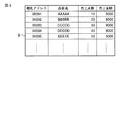
前記売上情報ファイル9は、図3に示すように、前記棚札アドレスにそれぞれ対応して品目名データと売上点数及び売上金額の売上実績データとを記憶するデータファイルである。売上実績データは、対応する棚札アドレスによって特定される電子棚札2が設けられた商品の開店から現時点までの売上合計点数及び売上合計金額であって、各商品の売上がある毎に、POSサーバ5の制御によりリアルタイムに書換更新されるようになっている。
As shown in FIG. 3, the
前記電子棚札2の正面図を図4に示す。また、前記電子棚札2のブロック構成図を図5に示す。電子棚札2は、薄板状をなす筐体21の正面に、品名,価格等を表示するための表示部22を設けている。また、駆動源としてのバッテリ23、無線基地局4を介して棚札サーバ1とデータ通信を行う通信部24、不揮発性の記憶部25及び各部を制御する制御部26を、筐体21に内蔵している。
A front view of the
記憶部25では、その電子棚札2に対して予め設定された前記棚札アドレスを固定的に記憶保持している。また、第1の画面情報を書換可能に記憶する第1画面メモリ27と、第2の画面情報を書換可能に記憶する第2画面メモリ28とを、記憶部25に形成している。
In the
第1画面メモリ27では、図4(a)に示すように、その電子棚札2が対応する商品の品目名と価格とが配置された商品価格画面の情報を記憶する。この商品価格画面上の品目名及び価格は、買物客に対して提示される情報であり、秘匿性はない。
As shown in FIG. 4A, the
一方、第2画面メモリ28では、図4(b)に示すように、その電子棚札2が対応する商品の品目名と売上点数及び売上金額とが配置された売上実績画面の情報を記憶する。この売上実績画面上の売上点数及び売上金額は、対応する商品の売上実績に関するデータであり、限られた店舗スタッフのみ閲覧が許される秘匿性のある情報である。ここに、第1,第2の画面メモリ27,28は、複数種類の表示情報を記憶する表示情報記憶部として機能する。
On the other hand, as shown in FIG. 4B, the
前記棚札サーバ1は、上記棚札情報ファイル8に記憶された情報に基づいて、電子棚札2別に商品価格画面の情報を作成し、それぞれ対応する無線基地局4を介して各電子棚札2に配信する機能と、上記売上情報ファイル9に記憶された情報に基づいて、電子棚札2別に売上実績画面の情報を作成し、それぞれ対応する無線基地局4を介して各電子棚札2に配信する機能とを有している。ここに、棚札サーバ1は、電子棚札2毎にそれぞれ複数種類の表示情報を生成して配信する表示情報配信手段、詳しくは、電子棚札毎にその棚札に対応する商品の品目名と価格とからなる棚札表示情報を生成して配信する棚札情報配信手段と、その電子棚札に対応する商品の売上実績データからなる売上実績情報を生成して配信する売上情報配信手段とを有している。
The
前記棚札サーバ1のブロック構成図を図6に示す。前記棚札サーバ1は、制御部本体を構成するCPU(Central Processing Unit)11、主記憶部を構成するROM(Read Only Memory)12及びRAM(Random Access Memory)13、補助記憶装置を構成するHDD(Hard Disk Drive)装置14、タイマ15、前記サーバ間ネットワーク6を介してPOSサーバ5との間で行うデータ通信を制御する第1の通信コントローラ16、前記通信回線3及び無線基地局4を介して各電子棚札2及びID認識装置7との間で行うデータ通信を制御する第2の通信コントローラ17等を備えている。
A block diagram of the
また、前記棚札サーバ1は、前記HDD装置14において、前記棚札情報ファイル8及び売上情報ファイル9の他、図7に示すデータ構造のグループ管理テーブル101、図8に示すデータ構造の棚札分類テーブル102、図9に示すデータ構造のアクセス権設定テーブル103を記憶している。
The
前記グループ管理テーブル101は、図7に示すように、先頭番号“1”から前記ID認識装置7の総数までの連続番号に対応して、ID認識アドレス,グループコード,許可中フラグ及びタイマ値(T値)をそれぞれ記憶するエリアを有している。そして、ID認識アドレスのエリアには、各ID認識装置7に対して予め割当設定された一意の無線通信アドレスであるID認識アドレスがセットされている。また、グループコードエリアには、対応するID認識アドレスで特定されるID認識装置7が所属するグループA,B,C,…を識別するためのグループコードがセットされている。また、許可中フラグエリアには、対応するグループコードで特定されるグループ内の各電子棚札2において、秘匿性のある売上実績データの閲覧を許可している状態にあるか禁止している状態にあるかを識別するための許可中フラグ(本実施の形態では「0:禁止、1:許可」とする。)がセットされている。タイマ値エリアには、対応するグループコードで特定されるグループ内の各電子棚札2において売上実績データの閲覧が許可されているとき、その許容時間の残り時間がセットされる。
As shown in FIG. 7, the group management table 101 includes an ID recognition address, a group code, a permission flag, and a timer value corresponding to consecutive numbers from the leading number “1” to the total number of the ID recognition devices 7 ( (T value) is stored. In the ID recognition address area, an ID recognition address that is a unique wireless communication address assigned and set in advance for each
前記棚札分類テーブル102には、図8に示すように、各電子棚札2をグループ分けしたグループを識別するグループコードに対応して、そのグループに属する全ての電子棚札2の棚札アドレスがセットされている。
In the shelf label classification table 102, as shown in FIG. 8, the shelf label addresses of all the
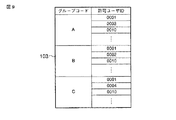
前記アクセス権設定テーブル103には、図9に示すように、各電子棚札2をグループ分けしたグループを識別するグループコードに対応して、そのグループに属する電子棚札2を利用して売上実績データの閲覧が可能な店舗スタッフのユーザIDがセットされている。
In the access right setting table 103, as shown in FIG. 9, the sales record using the
ここに、前記グループ管理テーブル101と棚札分類テーブル102とは、グループ毎にそのグループに属する電子棚札2とユーザID認識装置7とをそれぞれ識別する棚札アドレス及びID認識アドレスを記憶するグループ情報記憶部として機能する。
Here, the group management table 101 and the shelf label classification table 102 store a shelf label address and an ID recognition address for identifying the
また、前記アクセス権設定テーブル103は、グループ毎にそのグループに属する電子棚札2へのアクセス権を有するユーザIDを記憶するアクセス権情報記憶部として機能する。
The access right setting table 103 functions as an access right information storage unit that stores a user ID having an access right to the
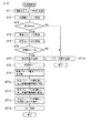
図10は、棚札サーバ1のCPU11が実行するID認識受信処理の要部手順を示す流れ図である。CPU11は、いずれかのID認識装置7においてユーザIDが認識されたことを、ID認識装置7から出力される認識結果の情報により判別すると、この処理を開始する。
FIG. 10 is a flowchart showing the main steps of the ID recognition receiving process executed by the
先ず、CPU11は、ST(ステップ)1としてID認識装置7で認識されたユーザIDをRAM13で記憶する。次に、ST2としてユーザIDを認識したID認識装置7の通信アドレスであるID認識アドレスを取得する。そして、ST3としてそのID認識アドレスで前記グループ管理テーブル101を検索して、当該ID認識アドレスに対応する許可中フラグが禁止状態(0)にあるか否かを判断する(認識有無識別手段)。
First, the
ここで、許可中フラグが禁止状態(0)にあると判別された場合には、CPU11は、ST4として前記グループ管理テーブル101当該ID認識アドレスに対応してセットされているグループコードを取得する。そして、ST5としてこのグループコードで前記アクセス権設定テーブル103を検索して、当該グループコードに対応してセットされている全ての許可ユーザIDを取得する。しかる後、CPU11は、ST6としてRAM13に記憶している認識ユーザIDと一致する許可ユーザIDの有無を判別する(アクセス権判断手段)。
If it is determined that the permission flag is in the prohibited state (0), the
ここで、認識ユーザIDと一致する許可ユーザIDが存在する場合には、ユーザIDで特定される店舗スタッフは、当該グループコードで特定されるグループ内の電子棚札2を用いて秘匿情報である売上実績データを確認することが許容された者なので、CPU11は、ST7として当該ID認識装置7に対してユーザIDが承認された旨の応答信号を第2の通信コントローラ17経由で送信する。また、ST8として前記グループ管理テーブル101の当該ID認識アドレスに対応する許可中フラグを禁止状態(0)から許可中状態(1)に更新する。
Here, if there is a permitted user ID that matches the recognized user ID, the store staff specified by the user ID is confidential information using the
次に、CPU11は、ST9として前記棚札分類テーブル102を参照して、当該グループコードに対応してセットされている全ての棚札アドレスを取得する。そして、ST10としてこれら棚札アドレスによってそれぞれ識別される電子棚札2毎に売上実績画面情報を作成する。すなわち、売上情報ファイル9から該当棚札アドレスに対応して記憶されている売上点数と売上金額の各データを品目名のデータとともに一画面内に配置してなる売上実績画面(図4の(b)を参照)の情報を作成する。
Next, the
次に、CPU11は、ST11として棚札アドレス毎に作成した売上実績画面情報を、それぞれ当該棚札アドレスによって特定される電子棚札2に、第2の通信コントローラ17を介して配信する。また、ST12として切替許可信号を同電子棚札2にそれぞれ配信する(切替許可指令手段)。しかる後、ST13としてグループ管理テーブル101の当該ID認識アドレスに対応するタイマ値エリアに、予め設定された許容時間初期値Tdefをセットして、今回の処理を終了する。
Next, the
なお、ST3にて許可中フラグが許可中状態(1)にあると判別された場合、及びST6にて認識ユーザIDと一致する許可ユーザIDが存在しないと判別された場合には、CPU11は、ST14として当該ID認識装置7に対してユーザIDの承認エラーである旨の応答信号を第2の通信コントローラ17経由で送信し、今回の処理を終了する。
If it is determined in ST3 that the permitted flag is in the permitted state (1), and if it is determined in ST6 that there is no permitted user ID that matches the recognized user ID, the
因みに、許容時間初期値Tdefは、ユーザ認証の結果承認された店舗スタッフが、そのグループ内の電子棚札2を用いて秘匿情報である売上実績データを確認することが許された時間であり、例えば5〜20秒程度に相当する値がプリセットされている。この時間は、短いとデータの確認が困難となるが、逆に長いと秘匿性を損ねるおそれがあり、これらを考慮して適切な時間を設定することが望ましい。
Incidentally, the allowable time initial value Tdef is a time when the store staff approved as a result of the user authentication is allowed to confirm the sales performance data as the confidential information using the
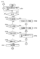
図11は、棚札サーバ1のCPU11が実行するタイマ割込受信処理の要部手順を示す流れ図である。CPU11は、タイマ15から周期的、例えば1秒間隔で発生されるタイマ割込信号を入力する毎に、この処理を開始する。
FIG. 11 is a flowchart showing the main procedure of the timer interrupt reception process executed by the
先ず、CPU11は、ST21としてRAM13に設けた番号カウンタnを“0”にリセットする。次に、ST22として上記番号カウンタnを“1”だけカウントアップする。そして、ST23としてこの番号カウンタnがグループ管理テーブル101の連続番号最大値Nを超えたか否かを判断する。
First, the
ここで、番号カウンタnが連続番号最大値Nを超えていない場合には、CPU11は、ST24としてこの番号カウンタnでグループ管理テーブル101を検索して当該番号nに対応するタイマ値Tnが“0”より大きい値か否かをチェックする。そして、タイマ値Tnが“0”の場合には、ST22の処理に戻り、番号カウンタnを“1”だけカウントアップし、連続番号最大値Nを超えていない場合には、再びタイマ値Tnが“0”より大きい値か否かのチェックを行う。
If the number counter n does not exceed the maximum consecutive number value N, the
その結果、タイマ値Tnが“0”より大きい値であった場合には、CPU11は、ST25としてそのタイマ値Tnを“1”だけ減算する。そして、ST26として減算後のタイマ値Tnが“0”になったか否かをチェックする。ここで、タイマ値Tnが依然として“0”より大きい場合には、ST22の処理に戻り、上記と同様の処理を再び実行する。
As a result, when the timer value Tn is larger than “0”, the
これに対し、減算後のタイマ値Tnが“0”になった場合には、CPU11は、ST27としてグループ管理テーブル101から当該番号nに対応して記憶されているグループコードを取得する。そして、ST28としてこの取得したグループコードで棚札分類テーブル102を検索して、当該グループコードに対応して記憶されている全ての棚札アドレスを取得する。
On the other hand, when the timer value Tn after the subtraction becomes “0”, the
次に、CPU11は、ST29として棚札分類テーブル102から取得した各棚札アドレスでそれぞれ識別される各電子棚札2に、第2の通信コントローラ17を介して切替禁止信号を配信する。しかる後、ST30としてグループ管理テーブル101の当該番号nに対応して記憶されている許可中フラグを“0”に変更したならば、ST22の処理に戻り、上記と同様な処理を繰り返す。
Next, the
こうして、ST23にて番号カウンタnが連続番号最大値Nを超えたことを確認したならば、CPU11は、今回のタイマ割込処理を終了する。
Thus, if it is confirmed in ST23 that the number counter n has exceeded the maximum consecutive number N, the
図12は、前記電子棚札2の制御部26が実行する主要な処理手順を示す流れ図である。すなわち制御部26は、ST41として第1画面メモリ27に記憶されている情報を基に、表示部22に商品価格画面を表示させる(表示制御手段)。この状態で、ST42として棚札サーバ1からの信号受信を待機する。なお、初期状態にあっては第1画面メモリ27に情報が記憶されていないので、商品価格画面を表示することなく棚札サーバ1からの信号受信を待機する。
FIG. 12 is a flowchart showing a main processing procedure executed by the
棚札サーバ1からの信号を受信したならば(ST42のYES)、制御部26は、ST43〜ST46としてその受信信号の種類を識別する。ここで、受信信号が商品価格画面を示す第1画面情報であった場合には(ST43のYES)、制御部26は、ST48としてこの第1画面情報を第1画面メモリ27に上書きして保存する。しかる後、ST41の処理に戻り、表示部22の商品価格画面を更新する。
If the signal from the
これに対し、受信信号が売上実績画面を示す第2画面情報であった場合には(ST44のYES)、制御部26は、ST49としてこの第2画面情報を第2画面メモリ28に上書きして保存する。しかる後、ST42の処理に戻って、次の信号受信を待機する。
On the other hand, when the received signal is the second screen information indicating the sales result screen (YES in ST44), the
一方、受信信号が切替許可信号であった場合には、制御部26は、ST50として第2画面メモリ28に記憶されている情報を基に売上実績画面を作成し、表示部22の画面をそれまでの商品価格画面から売上実績画面に切替える(表示切替手段)。しかる後、ST42の処理に戻って、次の信号受信を待機する。
On the other hand, when the received signal is a switching permission signal, the
また、受信信号が切替禁止信号であった場合には(ST46のYES)、制御部26は、ST41の処理に戻る。すなわち、表示部22の画面が売上実績画面であった場合には、第1画面メモリ27に記憶されている情報を基に商品価格画面に戻す。
If the received signal is a switching prohibition signal (YES in ST46),
次に、このように構成された本実施の形態の作用について説明する。
なお、説明の便宜上、グループAに属する電子棚札2及びID認識装置7をそれぞれ符号“2A”及び“7A”とし、このグループAに対応して設けられている無線基地局4を符号“4A”とする。同様に、グループB,Cに属する電子棚札2及びID認識装置7をそれぞれ符号“2B”,“2C”及び“7B” ,“7C”とし、このグループBまたはCに対応して設けられている無線基地局4をそれぞれ符号“4B”,“4C”とする。
Next, the operation of the embodiment configured as described above will be described.
For convenience of explanation, the
また、棚札情報ファイル8、売上情報ファイル9、グループ管理テーブル101、棚札分類テーブル102及びアクセス権設定テーブル103には、それぞれ図2,3,7,8,9に示すデータが記憶されているものとする。
Further, the shelf
例えば今、ユーザIDが「0001」のユーザがグループAに対応して設けられているID認識装置(ID認識アドレス=12345)7Aにより自身のユーザIDを認識させたとする。なお、グループ管理テーブル101のID認識アドレス“12345”に対応した許可中フラグは“0”にリセットされているものとする。 For example, it is assumed that a user with a user ID “0001” recognizes his / her user ID by an ID recognition device (ID recognition address = 134545) 7A provided corresponding to the group A. It is assumed that the permission flag corresponding to the ID recognition address “12345” in the group management table 101 is reset to “0”.
そうすると、このユーザID「0001」を認証結果とする情報信号がID認識装置7Aから無線送信され、無線基地局4Aを介して棚札サーバ1に送られる。これに応じて、棚札サーバ1においては、図10の流れ図に示した処理が実行される。すなわち、棚札サーバ1においては、ユーザID「0001」が認識され、ID認識装置のID認識アドレス“12345”が取得され、許可中フラグが“0”なので、グループコード“A”が取得され、このグループコード“A”に対応してアクセス権設定テーブル103に設定されている許可ユーザIDが取得される。ユーザID「0001」は、許可ユーザIDの中に含まれているので、ID認識装置7Aに承認応答が返信される。これにより、ID認識装置7Aでは、承認が報知されるので、当該ユーザは、ユーザIDが承認されたことを確認できる。
Then, an information signal having the user ID “0001” as an authentication result is wirelessly transmitted from the ID recognition device 7A and transmitted to the
また、棚札サーバ1においては、該当する許可中フラグが”1”となり、棚札分類テーブル102からグループコード“A”に属する全ての棚札アドレスが取得される。そして、この棚札アドレスで特定される電子棚札2毎に売上情報ファイル9の情報に基づいて売上実績画面の情報が作成され、これら売上実績画面の情報が無線基地局4Aを介して各電子棚札2Aに配信される。また、続いて、切替許可信号が各電子棚札2Aに配信される。
In the
その結果、各電子棚札2Aでは、表示部22の画面が価格表示画面から売上実績画面に自動的に切り替る。これにより、ユーザIDが承認されたことを確認したユーザは、各電子棚札2Aの表示内容により、各電子棚札2Aに対応する各商品の現時点までの売上点数及び売上金額の売上実績データを確認することができる。
As a result, in each electronic shelf label 2A, the screen of the
また、棚札サーバ1においては、グループ管理テーブル101のID認識アドレス“12345”に対応するタイマ値T1に初期値Tdefがセットされる。そして、タイマ15から割込信号が定期的に発生する毎に、このタイマ値T1が“1”ずつ減算される。そして、このタイマ値T1が“0”になると、グループコード“A”に属する全ての電子棚札2Aに対し、切替禁止信号が配信される。
In the
その結果、各電子棚札2Aでは、表示部22の画面が売上実績画面から価格表示画面に戻る。
As a result, in each electronic shelf label 2A, the screen of the
一方、ユーザIDが「0002」のユーザが同じくID認識装置7Aにより自身のユーザIDを認識させた場合には、このユーザID「0002」は、許可ユーザIDの中に含まれていないので、ID認識装置7Aにエラー応答が返信される。そしてこの場合は、各電子棚札2Aの表示画面は、価格表示画面のまま変化しない。 On the other hand, when the user with the user ID “0002” recognizes the user ID by the ID recognition device 7A, the user ID “0002” is not included in the permitted user ID. An error response is returned to the recognition device 7A. In this case, the display screen of each electronic shelf label 2A remains the price display screen.
このように、任意のグループに対して自身のユーザIDが許可ユーザIDとして設定され、アクセス権が与えられている店舗スタッフが、そのグループ内のID認識装置7により自身のユーザIDを認識させると、そのグループ内の全ての電子棚札2の画面表示が一定時間(Tdefに相当する時間)だけ価格表示から売上実績表示に自動的に切り替る。したがって、ID認識装置7においてユーザIDが承認された場合のみ秘匿性のある売上実績情報が電子棚札2の裏画面として表示されるので、秘匿性のある情報の表示にセキュリティ性を持たせることができる。
As described above, when a store staff member who is set with his / her own user ID as an authorized user ID for an arbitrary group and has the access right recognizes his / her user ID by the
しかも、本実施の形態の場合は、自身のユーザIDをID認識装置7で認識させるだけで、そのID認識装置7が属するグループ内の全ての電子棚札2の画面表示が売上実績表示に切り替るので、リモコンを操作して1つずつ確認していた従来と比べて確認作業の負担を大幅に軽減できる上、作業時間も大幅に短縮することができ、利便性の向上を図り得る。
Moreover, in the case of the present embodiment, the screen display of all the
ところで、上記第1の実施の形態では、ID認識装置7で認識されたユーザIDが、そのID認識装置7が属するグループに対して許可ユーザIDとして設定されていた場合に、当該ユーザIDを有する店舗スタッフに対してアクセス権を与えるとともに、当該グループ内の全ての電子棚札2の画面表示を価格表示から売上実績表示に一定時間だけ切替えるようにした。このため、そのグループ内に当該ユーザIDを有する店舗スタッフ以外のスタッフや買物客などがいた場合には、売上実績情報の秘匿性が失われる。
By the way, in the said 1st Embodiment, when the user ID recognized by the
そこで次に、このような問題をも解決した第2の実施の形態について図面を用いて説明する。なお、この第2の実施の形態は、第1の実施の形態において電子棚札2を以下の如く改良したものであり、第1の実施の形態と共通する部分には同一符号を付して、その詳しい説明を省略する。
Next, a second embodiment that solves such a problem will be described with reference to the drawings. In the second embodiment, the
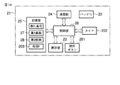
第2の実施の形態における電子棚札2の正面図を図13に示し、ブロック構成図を図14に示す。図示するように、電子棚札2は、筐体21の正面に、操作ボタン201を設けるとともに、その筐体21内にタイマ202を設け、これらを制御部26で制御可能としている。なお、操作ボタン201の取付位置は、筐体21の正面に限定されるものではなく、側面,上面,下面,背面等であってもよい。また電子棚札2は、記憶部25に有効フラグの記憶エリア203を形成している。
The front view of the
しかして、電子棚札2の制御部26は、図15の流れ図に示す手順で各部を処理する。なお図15も、第1の実施の形態の同処理手順を示す図12と共通する処理ステップには同一符号を付している。すなわち制御部26は、棚札サーバ1からの受信信号が切替許可信号であった場合には(ST45のYES)、ST51としてフラグ記憶エリア203の有効フラグを“1”にセットする。また、棚札サーバ1からの受信信号が切替禁止信号であった場合には(ST46のYES)、ST52として前記有効フラグを“0”にリセットする。その他の処理手順は、第1の実施の形態と同様である。
Therefore, the
また、電子棚札2の制御部26は、操作ボタン201が操作入力されたことにより発生する割込信号を取り込むと、図16の流れ図に示す割込処理を開始する。先ず、制御部26は、ST61として前記有効フラグをチェックする。そして、有効フラグが“0”にリセットされていた場合には、この割込処理を終了する。
Further, when the
有効フラグが“1”にセットされていた場合(ST61のYES)、制御部26は、ST62として第2画面メモリ28に記憶されている情報を基に売上実績画面を作成し、表示部22の画面をそれまでの商品価格画面から売上実績画面に切替える(表示切替手段)。
When the valid flag is set to “1” (YES in ST61), the
また、制御部26は、ST64としてタイマ202の計時動作を開始させる。そして、ST64として上記タイマ202がタイムアウトするのを待機する。なお、上記タイマ202は、棚札サーバ1において、グループ管理テーブル101のタイマ値エリアに設定される許容時間初期値Tdefに相当する時間よりも短い時間がタイムアウト時間として設定されている。
Moreover, the
制御部26は、上記タイマ202がタイムアウトするまでの間に、ST65として前記操作ボタン201が再入力されないか監視する。そして、タイムアウトする前に操作ボタン201が再入力されるか(ST65のYES)、タイマ202がタイムアウトした場合には(ST64のYES)、制御部26は、ST66として第1画面メモリ27に記憶されている情報を基に表示部22の画面を売上実績画面から商品価格画面に戻す。
The
このように本実施の形態においては、ID認識装置7で認識されたユーザIDが、そのID認識装置7が属するグループに対して許可ユーザIDとして設定されており、当該ユーザIDを有する店舗スタッフに対してアクセス権が与えられたとしても、そのグループに属する各電子棚札2においては、有効フラグが”1”にセットされるだけであり、表示画面は価格表示画面のままである。
As described above, in the present embodiment, the user ID recognized by the
しかしその後、許容時間初期値Tdefに相当する時間内に、当該ユーザがそのグループ内の電子棚札2の操作ボタン201を押下すると、その電子棚札2の表示画面だけが価格表示から売上実績表示に切り替る。このような表示の切替は、許容時間初期値Tdefに相当する時間内であれば可能であり、許容時間初期値Tdefが経過して棚札サーバ1から切替禁止信号が発せられると、有効フラグが“0”にリセットされて、操作ボタン201を押下しても画面が切り替らなくなる。
However, after that, when the user presses the
したがって、グループ内に他の店舗スタッフや買物客などがいた場合でも、アクセス権が許可された店舗スタッフが操作ボタン201を押下した電子棚札2以外の画面表示が切り替らないので、売上実績情報の秘匿性をより顕著なものとすることができる。
Therefore, even if there are other store staff, shoppers, etc. in the group, the screen display other than the
しかも、売上実績画面を表示してからタイマ202の計時時間が経過すると自動的に価格表示画面に復帰するだけでなく、操作ボタン201が再入力された場合には即座に価格表示画面に復帰するようにしたので、例えば買物客が近付いてきた場合には操作ボタン201が再入力して売上実績画面を消すことができ、売上実績情報の秘匿性をさらに顕著なものとすることができる。
Moreover, when the time measured by the
ところで、前記第1及び第2の実施の形態では、電子棚札2とは別にID認識装置7を設けた。このため、売上実績データを確認する店舗スタッフは、ID認識装置7を操作して自身のユーザIDを認証させた後、電子棚札2の前に移動して売上実績データを確認しなければならない面倒がある。
In the first and second embodiments, the
そこで次に、このような問題をも解決した第3の実施の形態について図面を用いて説明する。なお、この第3の実施の形態は、第1の実施の形態において電子棚札2を以下の如く改良したものであり、第1の実施の形態と共通する部分には同一符号を付して、その詳しい説明を省略する。
Next, a third embodiment that solves such a problem will be described with reference to the drawings. In the third embodiment, the
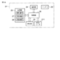
第3の実施の形態における電子棚札2の正面図を図17に示し、ブロック構成図を図18に示す。図示するように、電子棚札2は、筐体21の正面に、RFIDリーダ211を設けている。このRFIDリーダ211は、第1の実施の形態におけるID認識装置7と同様な機能を有するものである。
A front view of the
すなわち、RFIDリーダ211は、図示しないアンテナの交信領域内にRFカードが入ると、そのカードに内蔵されたRFIDからIDデータを非接触で読取る。そして、この読取ったIDデータを制御部26に出力する。
In other words, when an RF card enters an antenna communication area (not shown), the
すると、制御部26は、図19の流れ図に示す手順の処理を実行するものとなっている。すなわち制御部26は、ST71としてRFIDリーダ211によりRFIDのIDデータが読取られるのを待機し、読取られたならば、ST72としてそのIDデータが各店舗スタッフのユーザIDであるか否かを判別する。そして、ユーザIDであった場合には、ST73としてそのユーザIDを自身の棚札アドレスとともに棚札サーバ1に伝送する。その後、ST74として所定の待機時間を経過した後、ST71に戻り、IDデータが読取られるのを再び待機する。
Then, the
このような構成の第3の実施の形態においては、棚札サーバ1は、電子棚札2からユーザIDと棚札アドレスとのデータを受信すると、第1の実施の形態において図10を用いて説明したID認識受信処理を実行する。ただし、ST2の処理において、ID認識アドレスを取得するのでなく、棚札アドレスを取得し、棚札分類テーブル102を検索して、当該棚札アドレスに対応するグループコードを取得する。そして、ST3の処理においては、この取得したグループコードに対応する許可中フラグをチェックするように構成している。
In the third embodiment having such a configuration, when the
こうすることにより、第1の実施の形態と同様な作用効果を奏することができる。この場合において、売上実績データを確認する店舗スタッフは、電子棚札2のRFIDリーダ211に自身のRFカードを近づけるだけでID認証が行われるので、自身のユーザIDを認証させた後、電子棚札2の前に移動する面倒を解消することができる。また、ID認識装置7を設置するための店内スペースも不要にできる。
By doing so, the same operational effects as those of the first embodiment can be obtained. In this case, the store staff who confirms the sales performance data performs ID authentication only by bringing his / her RF card close to the
なお、RFIDリーダ211の代わりに生体認証装置等の他のID認識装置を電子棚札2と一体的に構成してもよい。また、全ての電子棚札2にID認識装置を一体的に組み込む必要はなく、少なくともグループ内の1つの電子棚札2をID認識装置と一体化したものとすればよい。
Instead of the
なお、この発明は前記実施形態そのままに限定されるものではなく、実施段階ではその要旨を逸脱しない範囲で構成要素を変形して具体化できる。 The present invention is not limited to the above-described embodiment as it is, and can be embodied by modifying the constituent elements without departing from the scope of the invention in the implementation stage.
例えば前記各実施の形態では、各電子棚札2で記憶する表示情報を秘匿性のない価格表示画面の情報と秘匿性のある売上実績画面の情報の2種類としたが、3種類以上を記憶し、例えば各ユーザIDに対応付けてどの種類の表示情報を表示させるかを予め設定して、ID認証装置7においていずれかのユーザIDが認証されたならば、そのユーザIDに対応付けられた種類の表示情報を表示部22に表示させるようにしてもよい。
For example, in each of the above-described embodiments, the display information stored in each
また、売上実績情報は、開店から現時点までの売上合計点数及び売上合計金額に限定されるものではなく、例えば時間帯別の売上合計点数及び売上合計金額であってもよい。また、曜日別,週別,月別の売上合計点数及び売上合計金額等であってもよい。また、秘匿性を有する表示情報は売上実績画面の情報に限定されるものではなく、例えば在庫数,発注数等を示す画面情報であってもよい。 The sales performance information is not limited to the total sales score and the total sales amount from the opening of the store to the present time, and may be, for example, the total sales score and the total sales amount for each time zone. Further, the total sales score and total sales amount by day of the week, week, month may be used. Further, the display information having confidentiality is not limited to the information on the sales performance screen, and may be screen information indicating the number of stocks, the number of orders, etc., for example.
また、前記実施の形態では、各電子棚札2を分類するグループA,B,C,…にそれぞれ対応して無線基地局4を設けたが、必ずしも1つのグループに対して1台の無線基地局4を関連付ける必要はなく、2以上のグループに対して1台の無線基地局4を関連付けしてもよいし、1つのグループに対して複数の無線基地局4を関連付けしてもよい。
Moreover, in the said embodiment, although the
また、前記実施の形態では、アクセス権設定テーブル103は、グループ毎にそのグループに属する電子棚札2へのアクセス権を有するユーザIDを記憶するようにしたが、アクセス権を有さないユーザIDを記憶し、図10中ST6の処理で、認識したユーザIDと同一のユーザIDが当該アクセス権設定テーブル103に設定されていない場合にはST7の処理に進み、設定されていた場合にはST14の処理に進むようにしてもよい。
Moreover, in the said embodiment, although the access right setting table 103 memorize | stored user ID which has the access right to the
また、前記各実施の形態では、売上実績画面が電子棚札2に表示されている時間を共通としたが、ユーザによって表示時間を可変設定できるようにしてもよい。
Moreover, in each said embodiment, although the time when the sales performance screen was displayed on the
また、本発明は電子棚札システムへの適用に限定されるものではなく、商品価格情報に加えて販促情報や顧客サービス情報,商品情報等を表示して買物客をサポートする電子POSシステム等の店舗内の情報表示ステム全般に適用できるものである。 In addition, the present invention is not limited to application to an electronic shelf label system, such as an electronic POS system that supports shoppers by displaying sales promotion information, customer service information, product information, etc. in addition to product price information. It can be applied to all information display systems in stores.
この他、前記実施形態に開示されている複数の構成要素の適宜な組合せにより種々の発明を形成できる。例えば、実施形態に示される全構成要素から幾つかの構成要素を削除してもよい。さらに、異なる実施形態に亘る構成要素を組合わせてもよい。 In addition, various inventions can be formed by appropriately combining a plurality of constituent elements disclosed in the embodiment. For example, some components may be deleted from all the components shown in the embodiment. Furthermore, the constituent elements over different embodiments may be combined.
1…棚札サーバ、2…電子棚札、4…無線基地局、5…POSサーバ、7…ID認識装置、8…棚札情報ファイル、9…売上情報ファイル、11…CPU、14…HDD装置、22…表示部、26…制御部、27…第1画面メモリ、28…第2画面メモリ、101…グループ管理テーブル、102…棚札分類テーブル、103…アクセス権設定テーブル、201…操作ボタン、211…RFIDリーダ。
DESCRIPTION OF
Claims (14)
前記各情報表示端末は、複数のグループにグループ分けされ、各グループにそれぞれ対応して少なくとも1つのユーザID認識装置が前記サーバ装置と通信自在に設けられ、
前記サーバ装置は、前記グループ毎にそのグループに属する前記情報表示端末と前記ユーザID認識装置とをそれぞれ識別する情報を記憶するグループ情報記憶部と、前記情報表示端末毎にそれぞれ複数種類の表示情報を生成して配信する表示情報配信手段と、いずれかの前記ユーザID認識装置にてユーザIDが認識されたか否かを識別する認識有無識別手段と、この認識有無識別手段により前記ユーザIDが認識された前記ユーザID認識装置を識別すると、そのユーザID認識装置が属するグループに分類された全ての前記情報表示端末を前記グループ情報記憶部に記憶された情報を基に特定し、その特定された全ての前記情報表示端末に対して切替許可信号を配信する切替許可指令手段とを具備し、
前記各情報表示端末は、前記複数種類の表示情報を記憶する表示情報記憶部と、この表示情報記憶部に記憶された複数種類の表示情報のうち所定の表示情報を前記表示部に表示させる表示制御手段と、前記サーバ装置から前記切替許可信号を受信すると、前記表示部の表示情報を一定時間だけ前記表示情報記憶部に記憶された別の表示情報に切替える表示切替手段とを具備し、
たことを特徴とする情報表示システム。 In an information display system in which a server device and a plurality of information display terminals having a display unit capable of displaying information received from the server device are connected by wired or wireless communication means,
Each of the information display terminals is grouped into a plurality of groups, and at least one user ID recognition device corresponding to each group is provided to be able to communicate with the server device,
The server device includes a group information storage unit that stores information for identifying the information display terminal belonging to the group and the user ID recognition device for each group, and a plurality of types of display information for each information display terminal. Display information distribution means for generating and distributing information, recognition presence / absence identification means for identifying whether or not the user ID is recognized by any of the user ID recognition devices, and the user ID is recognized by the recognition presence / absence identification means When the identified user ID recognition device is identified, all the information display terminals classified into the group to which the user ID recognition device belongs are identified based on the information stored in the group information storage unit, and the identified Switching permission command means for distributing a switching permission signal to all the information display terminals,
Each of the information display terminals includes a display information storage unit that stores the plurality of types of display information, and a display that displays predetermined display information on the display unit among the plurality of types of display information stored in the display information storage unit. A control means, and a display switching means for switching the display information of the display section to another display information stored in the display information storage section for a predetermined time when the switching permission signal is received from the server device,
An information display system characterized by that.
前記表示切替手段は、前記操作子が操作入力されると、前記サーバ装置から前記切替許可信号を受信していることを条件に、前記表示部の表示情報を一定時間だけ前記表示情報記憶部に記憶された別の表示情報に切替えることを特徴とする請求項1記載の情報表示システム。 Each of the information display terminals further includes an operator for instructing switching of display information,
The display switching means stores the display information of the display unit in the display information storage unit for a predetermined time on condition that the switching permission signal is received from the server device when the operation element is operated. 2. The information display system according to claim 1, wherein the display information is switched to another stored display information.
前記切替許可指令手段は、前記アクセス権判断手段によりアクセス権を有するユーザIDを認識したと判断されたことを条件に、該当する情報表示端末に対して切替許可信号を配信することを特徴とする請求項1記載の情報表示システム。 The server device includes, for each group, an access right information storage unit that stores a user ID having an access right to the information display terminal belonging to the group or a user ID having no access right, and the recognition presence / absence identifying unit. When the user ID recognizing device whose user ID is recognized is identified, the user ID having access right to the group to which the user ID recognizing device belongs is recognized with reference to the storage information of the access right information storage unit. And an access right judging means for judging whether or not
The switching permission instruction means delivers a switching permission signal to the corresponding information display terminal on the condition that the access right determination means determines that the user ID having the access right is recognized. The information display system according to claim 1.
前記サーバ装置は、各商品の品目名と価格とを関連付けて記憶する棚札情報ファイルと、各商品の売上実績データを記憶する売上情報ファイルとを具備し、
前記表示情報配信手段は、前記情報表示端末毎にその端末に対応する商品の品目名と価格とからなる棚札表示情報を前記棚札情報ファイルに記憶されたデータを基に生成して配信する棚札情報配信手段と、前記情報表示端末毎にその端末に対応する商品の売上実績データからなる売上実績情報を前記売上情報ファイルに記憶されたデータを基に生成して配信する売上情報配信手段とを含み、
前記各情報表示端末の表示情報記憶部は、前記棚札表示情報を記憶する第1の記憶部と前記売上実績情報を記憶する第2の記憶部とを含み、
前記表示制御手段は、前記第1の記憶部に記憶された棚札表示情報を前記表示部に表示させ、前記表示切替手段は、前記表示部の表示情報を前記第2の記憶部に記憶された売上実績情報に切替えることを特徴とする請求項1乃至5のうちいずれか一記載の情報表示システム。 Each information display terminal is provided corresponding to each item of each product,
The server device includes a shelf label information file that stores the item name and price of each product in association with each other, and a sales information file that stores sales performance data of each product,
The display information distribution unit generates and distributes shelf label display information including item names and prices of products corresponding to the terminal for each information display terminal based on data stored in the shelf label information file. Sales label information distribution means, and sales information distribution means for generating and distributing sales record information consisting of sales record data of products corresponding to the terminal for each information display terminal based on the data stored in the sales information file Including
The display information storage unit of each information display terminal includes a first storage unit that stores the shelf label display information and a second storage unit that stores the sales performance information,
The display control unit causes the display unit to display the shelf label display information stored in the first storage unit, and the display switching unit stores the display information of the display unit in the second storage unit. 6. The information display system according to claim 1, wherein the information display system is switched to the sales result information.
前記各情報表示端末を複数のグループに区分するグループ毎に、そのグループに属する前記情報表示端末とそのグループに対応して設けられたユーザID認識装置とをそれぞれ識別する情報を記憶するグループ情報記憶部と、前記情報表示端末毎にそれぞれ複数種類の表示情報を生成して配信する表示情報配信手段と、いずれかの前記ユーザID認識装置にてユーザIDが認識されたか否かを識別する認識有無識別手段と、この認識有無識別手段により前記ユーザIDが認識された前記ユーザID認識装置を識別すると、そのユーザID認識装置が属するグループに分類された全ての前記情報表示端末を前記グループ情報記憶部に記憶された情報を基に特定し、その特定された全ての前記情報表示端末に対して切替許可信号を配信する切替許可指令手段とを具備したことを特徴とするサーバ装置。 In a server device that connects a plurality of information display terminals having a display unit by wired or wireless communication means, and manages information display of each information display terminal,
Group information storage for storing information for identifying each of the information display terminals belonging to the group and a user ID recognition device provided corresponding to the group for each group that divides each information display terminal into a plurality of groups A display information distribution unit that generates and distributes a plurality of types of display information for each information display terminal, and whether or not a user ID is recognized by any of the user ID recognition devices When the identification unit and the user ID recognition device whose user ID is recognized by the recognition presence / absence identification unit are identified, all the information display terminals classified into the group to which the user ID recognition device belongs are stored in the group information storage unit. The switching permission is specified based on the information stored in the information, and the switching permission signal is distributed to all of the identified information display terminals. Server apparatus being characterized in that; and a command means.
前記切替許可指令手段は、前記アクセス権判断手段によりアクセス権を有するユーザIDを認識したと判断されたことを条件に、該当する情報表示端末に対して切替許可信号を配信することを特徴とする請求項8記載のサーバ装置。 The user ID is recognized by the access right information storage unit for storing a user ID having an access right to the information display terminal belonging to the group or a user ID having no access right for each group, and the recognition presence / absence identifying unit. When the identified user ID recognition device is identified, it is determined whether or not a user ID having an access right for the group to which the user ID recognition device belongs is recognized by referring to the storage information in the access right information storage unit. And an access right judging means for
The switching permission instruction means delivers a switching permission signal to the corresponding information display terminal on the condition that the access right determination means determines that the user ID having the access right is recognized. The server device according to claim 8.
複数種類の表示情報を記憶する表示情報記憶部と、この表示情報記憶部に記憶された複数種類の表示情報のうち所定の表示情報を前記表示部に表示させる表示制御手段と、表示情報の切替を指示するための操作子と、前記操作子が操作入力されると、外部から切替許可信号を受信していることを条件に、前記表示部の表示情報を一定時間だけ前記表示情報記憶部に記憶された別の表示情報に切替える表示切替手段とを具備したことを特徴とする情報表示端末。 In an information display terminal having a display unit capable of displaying information received from outside,
Display information storage unit for storing a plurality of types of display information, display control means for displaying predetermined display information among the plurality of types of display information stored in the display information storage unit, and switching of the display information The display information stored in the display unit is stored in the display information storage unit for a predetermined time on the condition that a switching permission signal is received from the outside when the operation unit is operated and input. An information display terminal comprising display switching means for switching to another stored display information.
前記情報表示端末グループ毎にそのグループに属する前記情報表示端末とそのグループに対応して設けられたユーザID認識装置とをそれぞれ識別する情報を記憶するグループ情報記憶部、前記情報表示端末毎にそれぞれ複数種類の表示情報を生成して配信する表示情報配信手段、いずれかの前記ユーザID認識装置にてユーザIDが認識されたか否かを識別する認識有無識別手段、及び、前記認識有無識別手段により前記ユーザIDが認識された前記ユーザID認識装置を識別すると、そのユーザID認識装置が属するグループに分類された全ての前記情報表示端末を前記グループ情報記憶部に記憶された情報を基に特定し、その特定された全ての前記情報表示端末に対して切替許可信号を配信する切替許可指令手段、を備えたサーバ装置と有線または無線の通信手段で接続してなり、 For each information display terminal group, a group information storage unit for storing information for identifying each of the information display terminals belonging to the group and a user ID recognition device provided corresponding to the group, and for each information display terminal Display information distribution means for generating and distributing a plurality of types of display information, recognition presence / absence identification means for identifying whether or not a user ID is recognized by any of the user ID recognition devices, and recognition recognition / identification means When the user ID recognition device whose user ID is recognized is identified, all the information display terminals classified into the group to which the user ID recognition device belongs are specified based on the information stored in the group information storage unit. And a switching permission instruction means for distributing a switching permission signal to all of the specified information display terminals. Be connected by wired or wireless communication means,
前記サーバ装置から受信した情報を表示可能な表示部と、複数種類の表示情報を記憶する表示情報記憶部と、この表示情報記憶部に記憶された複数種類の表示情報のうち所定の表示情報を前記表示部に表示させる表示制御手段と、前記サーバ装置から前記切替許可信号を受信すると、前記表示部の表示情報を一定時間だけ前記表示情報記憶部に記憶された別の表示情報に切替える表示切替手段と、を具備したことを特徴とする情報表示端末。 A display unit capable of displaying information received from the server device; a display information storage unit for storing a plurality of types of display information; and predetermined display information among a plurality of types of display information stored in the display information storage unit. Display control means for displaying on the display unit, and display switching for switching the display information on the display unit to another display information stored in the display information storage unit for a predetermined time when the switching permission signal is received from the server device And an information display terminal.
前記表示切替手段は、前記操作子が操作入力されると、前記サーバ装置から前記切替許可信号を受信していることを条件に、前記表示部の表示情報を一定時間だけ前記表示情報記憶部に記憶された別の表示情報に切替えることを特徴とする請求項12記載の情報表示端末。 The display switching means stores the display information of the display unit in the display information storage unit for a predetermined time on condition that the switching permission signal is received from the server device when the operation element is operated. The information display terminal according to claim 12, wherein the information display terminal is switched to another stored display information.
Priority Applications (1)
| Application Number | Priority Date | Filing Date | Title |
|---|---|---|---|
| JP2006303143A JP5000269B2 (en) | 2006-11-08 | 2006-11-08 | Information display system, server device, and information display terminal |
Applications Claiming Priority (1)
| Application Number | Priority Date | Filing Date | Title |
|---|---|---|---|
| JP2006303143A JP5000269B2 (en) | 2006-11-08 | 2006-11-08 | Information display system, server device, and information display terminal |
Publications (2)
| Publication Number | Publication Date |
|---|---|
| JP2008123046A JP2008123046A (en) | 2008-05-29 |
| JP5000269B2 true JP5000269B2 (en) | 2012-08-15 |
Family
ID=39507768
Family Applications (1)
| Application Number | Title | Priority Date | Filing Date |
|---|---|---|---|
| JP2006303143A Expired - Fee Related JP5000269B2 (en) | 2006-11-08 | 2006-11-08 | Information display system, server device, and information display terminal |
Country Status (1)
| Country | Link |
|---|---|
| JP (1) | JP5000269B2 (en) |
Families Citing this family (8)
| Publication number | Priority date | Publication date | Assignee | Title |
|---|---|---|---|---|
| JP2011186659A (en) | 2010-03-05 | 2011-09-22 | Toshiba Tec Corp | Electronic shelf label system, advertisement terminal and program |
| JP6134657B2 (en) | 2014-01-16 | 2017-05-24 | 東芝テック株式会社 | Electronic shelf label system, electronic shelf label terminal, electronic shelf label server and control program thereof |
| JP6156430B2 (en) * | 2015-04-09 | 2017-07-05 | カシオ計算機株式会社 | Display terminal and program |
| US12169818B2 (en) | 2016-05-04 | 2024-12-17 | Mariella Labels Oy | Simultaneously displaying new prices linked to products via an electronic price label system |
| US20170323317A1 (en) * | 2016-05-04 | 2017-11-09 | Mariella Labels Oy | Electronic price label system |
| CN207115451U (en) * | 2017-04-01 | 2018-03-16 | 广州奥翼电子科技股份有限公司 | Electronic bin tag system component |
| JP7505220B2 (en) * | 2020-03-25 | 2024-06-25 | 日本電気株式会社 | Processing device, processing method, and program |
| JP7438879B2 (en) * | 2020-07-22 | 2024-02-27 | 東芝テック株式会社 | Systems, shelving equipment and cart POS |
Family Cites Families (3)
| Publication number | Priority date | Publication date | Assignee | Title |
|---|---|---|---|---|
| JP2001266252A (en) * | 2000-03-15 | 2001-09-28 | Toshiba Tec Corp | Electronic shelf label system |
| JP3603778B2 (en) * | 2000-10-31 | 2004-12-22 | 株式会社寺岡精工 | Electronic shelf label system |
| JP2004265195A (en) * | 2003-03-03 | 2004-09-24 | Ishida Co Ltd | Method of associating electronic shelf label with product, electronic shelf label system, and information acquisition device |
-
2006
- 2006-11-08 JP JP2006303143A patent/JP5000269B2/en not_active Expired - Fee Related
Also Published As
| Publication number | Publication date |
|---|---|
| JP2008123046A (en) | 2008-05-29 |
Similar Documents
| Publication | Publication Date | Title |
|---|---|---|
| US7654453B2 (en) | Merchandise registration processing system | |
| JP4629510B2 (en) | Product information display system and electronic shelf label | |
| US6513015B2 (en) | System and method for customer recognition using wireless identification and visual data transmission | |
| US7183925B2 (en) | Interactive system using tags | |
| JP5000269B2 (en) | Information display system, server device, and information display terminal | |
| WO2008035659A1 (en) | Accounting device, ic chip, terminal device, accounting method and information processing method | |
| US20130043303A1 (en) | Electronic transaction system | |
| JP2007141150A (en) | Product information display system | |
| JP4764132B2 (en) | Store system | |
| US6769610B2 (en) | Credit card double authentication system | |
| JP5100345B2 (en) | Service consumption confirmation system | |
| JP4621131B2 (en) | Product information display system | |
| JP2006215897A (en) | Merchandise management system | |
| WO2003083744A1 (en) | System, method, device, program, and portable terminal for supporting attendance | |
| JP4083648B2 (en) | Order accounting system | |
| US20070210945A1 (en) | Personal multiple-identification device | |
| KR20070078742A (en) | Card merchant payment terminal device and program recording medium | |
| KR101124309B1 (en) | System for Approving the RFID Information Corresponded to Purchased Commodities | |
| JP6849175B2 (en) | Health management system | |
| JP2005135156A (en) | Product management system | |
| JP2005267181A (en) | Product information providing system and method | |
| KR20070048011A (en) | Item purchase system using RFID card | |
| KR20090099840A (en) | Electronic Voucher Service System and Method Using Smart Card | |
| JPH0446027B2 (en) | ||
| KR20040028274A (en) | Customer management system using recognition of fingerprint and method thereof |
Legal Events
| Date | Code | Title | Description |
|---|---|---|---|
| A621 | Written request for application examination |
Free format text: JAPANESE INTERMEDIATE CODE: A621 Effective date: 20080910 |
|
| A977 | Report on retrieval |
Free format text: JAPANESE INTERMEDIATE CODE: A971007 Effective date: 20110829 |
|
| A131 | Notification of reasons for refusal |
Free format text: JAPANESE INTERMEDIATE CODE: A131 Effective date: 20110913 |
|
| A521 | Request for written amendment filed |
Free format text: JAPANESE INTERMEDIATE CODE: A523 Effective date: 20111114 |
|
| TRDD | Decision of grant or rejection written | ||
| A01 | Written decision to grant a patent or to grant a registration (utility model) |
Free format text: JAPANESE INTERMEDIATE CODE: A01 Effective date: 20120508 |
|
| A01 | Written decision to grant a patent or to grant a registration (utility model) |
Free format text: JAPANESE INTERMEDIATE CODE: A01 |
|
| A61 | First payment of annual fees (during grant procedure) |
Free format text: JAPANESE INTERMEDIATE CODE: A61 Effective date: 20120516 |
|
| R150 | Certificate of patent or registration of utility model |
Free format text: JAPANESE INTERMEDIATE CODE: R150 |
|
| FPAY | Renewal fee payment (event date is renewal date of database) |
Free format text: PAYMENT UNTIL: 20150525 Year of fee payment: 3 |
|
| LAPS | Cancellation because of no payment of annual fees |