JP5000372B2 - 蛍光ランプ及びそれを用いた照明装置 - Google Patents
蛍光ランプ及びそれを用いた照明装置 Download PDFInfo
- Publication number
- JP5000372B2 JP5000372B2 JP2007117220A JP2007117220A JP5000372B2 JP 5000372 B2 JP5000372 B2 JP 5000372B2 JP 2007117220 A JP2007117220 A JP 2007117220A JP 2007117220 A JP2007117220 A JP 2007117220A JP 5000372 B2 JP5000372 B2 JP 5000372B2
- Authority
- JP
- Japan
- Prior art keywords
- temperature protection
- fluorescent tube
- protection element
- base
- fluorescent
- Prior art date
- Legal status (The legal status is an assumption and is not a legal conclusion. Google has not performed a legal analysis and makes no representation as to the accuracy of the status listed.)
- Expired - Fee Related
Links
Images




Landscapes
- Arrangement Of Elements, Cooling, Sealing, Or The Like Of Lighting Devices (AREA)
- Non-Portable Lighting Devices Or Systems Thereof (AREA)
- Common Detailed Techniques For Electron Tubes Or Discharge Tubes (AREA)
Description
以下、本発明の蛍光ランプの実施形態を図面に基づき説明する。以下の図面では、同一部分には同一の符号を付けて、重複する説明は省略する場合がある。
次に、本発明の照明装置の実施形態について説明する。図8は、本発明の照明装置の一例を示す斜視図である。図8において、照明装置50は、蛍光ランプ51を備えている。蛍光ランプ51としては、実施形態1で説明した蛍光ランプをそのまま使用している。実施形態1の蛍光ランプ51を用いることにより、照明装置50の寿命末期での安全性を向上できる。
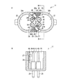
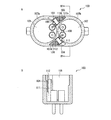
図1〜図3に示した蛍光ランプと同様の蛍光ランプとして、管外径20mmのバルブ12a、12bをブリッジ接続して形成した全長410mmの蛍光管12と、PBT樹脂よりなる長さ(L)47mm、幅(W)25mmの口金11とからなる定格200V、36Wの蛍光ランプを作製した。温度保護素子26、27として、溶断温度が140℃付近にあるものを用いた。温度保護素子26、27と電極封止部18、19との最短距離は、2mmとした。口金11と、蛍光管12及び蓋44、45との接合は、ともにシリコーン樹脂を用い、温度保護素子収納部32、33内にはシリコーン樹脂を充填しなかった。
温度保護素子27を除去してリード線23を端子29に直接接続した以外は、実施例1と同様にして蛍光ランプを作製した。
口金として図9に示した口金100を用い、実施例2と同様にして温度保護素子104を除去して温度保護素子103のみを用いた以外は、実施例1と同様にして蛍光ランプを作製した。
11 口金
12 蛍光管
12a、12b バルブ
13 ブリッジ接続部
14、15 電極
16、17 ステム
18、19 電極封止部
20、21、22、23、26a、26b、27a、27b リード線
24、25、28、29 端子
26、27 温度保護素子
30、31 蛍光管収納部
32、33 温度保護素子収納部
34a、34b、34c、34d 外壁
35、36 突出片
37、38、39、40 支持部材
41 支持片
42 支持柱
43 接着剤
44、45 蓋
46 隙間
50 照明装置
51 蛍光ランプ
Claims (6)
- 口金と、前記口金に固定保持された蛍光管と、温度保護素子とを備えた蛍光ランプであって、
前記蛍光管は、両端部に電極が封止された電極封止部を備えているとともに、内部に屈曲した放電路を有し、
前記口金は、前記蛍光管の前記電極封止部を収納するための蛍光管収納部と、前記温度保護素子を収納するための温度保護素子収納部とを備え、
前記蛍光管収納部は、前記口金の外壁と、前記外壁から前記蛍光管の各前記電極封止部に向かって突出する2つの突出片とから形成され、
前記2つの突出片の先端部間には隙間が形成されており、
前記温度保護素子収納部は、前記外壁と、前記突出片の1つとから形成され、
前記電極封止部は、前記蛍光管収納部に配設され、
前記温度保護素子は、前記温度保護素子収納部に配設され、
前記電極は、前記温度保護素子と接続されていることを特徴とする蛍光ランプ。 - 前記2つの突出片の先端部間に、前記突出片とそれぞれ所定の間隔を有する支持片がさらに設けられている請求項1に記載の蛍光ランプ。
- 前記2つの突出片の先端部間に、前記突出片と所定の間隔を有する支持柱がさらに設けられている請求項1に記載の蛍光ランプ。
- 前記蛍光管は、前記口金に接着剤により固着されている請求項1〜3のいずれか1項に記載の蛍光ランプ。
- 前記温度保護素子収納部には、空間が存在する請求項1〜4のいずれか1項に記載の蛍光ランプ。
- 請求項1〜5のいずれか1項に記載の蛍光ランプを備えていることを特徴とする照明装置。
Priority Applications (1)
| Application Number | Priority Date | Filing Date | Title |
|---|---|---|---|
| JP2007117220A JP5000372B2 (ja) | 2007-04-26 | 2007-04-26 | 蛍光ランプ及びそれを用いた照明装置 |
Applications Claiming Priority (1)
| Application Number | Priority Date | Filing Date | Title |
|---|---|---|---|
| JP2007117220A JP5000372B2 (ja) | 2007-04-26 | 2007-04-26 | 蛍光ランプ及びそれを用いた照明装置 |
Publications (2)
| Publication Number | Publication Date |
|---|---|
| JP2008277043A JP2008277043A (ja) | 2008-11-13 |
| JP5000372B2 true JP5000372B2 (ja) | 2012-08-15 |
Family
ID=40054775
Family Applications (1)
| Application Number | Title | Priority Date | Filing Date |
|---|---|---|---|
| JP2007117220A Expired - Fee Related JP5000372B2 (ja) | 2007-04-26 | 2007-04-26 | 蛍光ランプ及びそれを用いた照明装置 |
Country Status (1)
| Country | Link |
|---|---|
| JP (1) | JP5000372B2 (ja) |
Family Cites Families (5)
| Publication number | Priority date | Publication date | Assignee | Title |
|---|---|---|---|---|
| JPH0817335A (ja) * | 1994-06-30 | 1996-01-19 | Toshiba Lighting & Technol Corp | コンパクト形蛍光ランプ |
| JP3843556B2 (ja) * | 1997-09-30 | 2006-11-08 | 東芝ライテック株式会社 | 蛍光ランプおよび照明装置 |
| JP3032504B2 (ja) * | 1998-07-10 | 2000-04-17 | 松下電子工業株式会社 | 蛍光ランプ、この蛍光ランプの製造方法およびこの蛍光ランプを用いた照明装置 |
| JP3293612B2 (ja) * | 1999-10-29 | 2002-06-17 | 松下電器産業株式会社 | 蛍光ランプ |
| JP2004063405A (ja) * | 2002-07-31 | 2004-02-26 | Toshiba Lighting & Technology Corp | 蛍光ランプおよび照明器具 |
-
2007
- 2007-04-26 JP JP2007117220A patent/JP5000372B2/ja not_active Expired - Fee Related
Also Published As
| Publication number | Publication date |
|---|---|
| JP2008277043A (ja) | 2008-11-13 |
Similar Documents
| Publication | Publication Date | Title |
|---|---|---|
| JP5371787B2 (ja) | 高圧放電ランプ | |
| JP3032504B2 (ja) | 蛍光ランプ、この蛍光ランプの製造方法およびこの蛍光ランプを用いた照明装置 | |
| JP2008277043A (ja) | 蛍光ランプ及びそれを用いた照明装置 | |
| US10784099B2 (en) | Incandescent light bulb | |
| JP5678080B2 (ja) | 片側ソケット型高圧放電ランプ | |
| JP2015076306A (ja) | ショートアーク型放電ランプ | |
| CN201229927Y (zh) | 具有辐射保护夹的电灯 | |
| JP2009140846A (ja) | 車輌用放電灯 | |
| JP2013196928A (ja) | フィラメントランプおよび加熱装置 | |
| CN102971830B (zh) | 陶瓷金属卤化物灯 | |
| JP6020607B2 (ja) | 両端封止型ショートアークフラッシュランプ | |
| KR101094092B1 (ko) | 고휘도 방전램프 | |
| CN101359569B (zh) | 灯泡形荧光灯以及照明器具 | |
| JP4624337B2 (ja) | 蛍光ランプ | |
| KR20090015914A (ko) | 고압력 가스 방전 램프 및 그 제조 방법 | |
| CN105914127A (zh) | 两端密封型短弧闪光灯 | |
| JP4921141B2 (ja) | 環形蛍光ランプ | |
| JP2006302522A (ja) | 電球型ヒータ、点灯装置 | |
| JP2012043588A (ja) | 金属蒸気放電ランプおよび照明装置 | |
| JP2009076352A (ja) | 蛍光ランプおよび照明装置 | |
| JP2008181780A (ja) | 蛍光ランプおよび照明器具 | |
| KR200472314Y1 (ko) | 고휘도 방전램프 | |
| KR20080105777A (ko) | 할로겐 사이클 백열 램프 | |
| JP2007134330A (ja) | メタルハライドアーク放電ランプ | |
| JP2006236756A (ja) | ショートアーク型放電灯 |
Legal Events
| Date | Code | Title | Description |
|---|---|---|---|
| A621 | Written request for application examination |
Free format text: JAPANESE INTERMEDIATE CODE: A621 Effective date: 20100225 |
|
| A977 | Report on retrieval |
Free format text: JAPANESE INTERMEDIATE CODE: A971007 Effective date: 20111021 |
|
| A131 | Notification of reasons for refusal |
Free format text: JAPANESE INTERMEDIATE CODE: A131 Effective date: 20111101 |
|
| A521 | Request for written amendment filed |
Free format text: JAPANESE INTERMEDIATE CODE: A523 Effective date: 20111221 |
|
| TRDD | Decision of grant or rejection written | ||
| A01 | Written decision to grant a patent or to grant a registration (utility model) |
Free format text: JAPANESE INTERMEDIATE CODE: A01 Effective date: 20120508 |
|
| A01 | Written decision to grant a patent or to grant a registration (utility model) |
Free format text: JAPANESE INTERMEDIATE CODE: A01 |
|
| A61 | First payment of annual fees (during grant procedure) |
Free format text: JAPANESE INTERMEDIATE CODE: A61 Effective date: 20120516 |
|
| R150 | Certificate of patent or registration of utility model |
Ref document number: 5000372 Country of ref document: JP Free format text: JAPANESE INTERMEDIATE CODE: R150 Free format text: JAPANESE INTERMEDIATE CODE: R150 |
|
| FPAY | Renewal fee payment (event date is renewal date of database) |
Free format text: PAYMENT UNTIL: 20150525 Year of fee payment: 3 |
|
| LAPS | Cancellation because of no payment of annual fees |