JP5000989B2 - Information processing apparatus, information processing method, and program - Google Patents

Information processing apparatus, information processing method, and program Download PDF

Info

Publication number
JP5000989B2
JP5000989B2 JP2006316302A JP2006316302A JP5000989B2 JP 5000989 B2 JP5000989 B2 JP 5000989B2 JP 2006316302 A JP2006316302 A JP 2006316302A JP 2006316302 A JP2006316302 A JP 2006316302A JP 5000989 B2 JP5000989 B2 JP 5000989B2
Authority
JP
Japan
Prior art keywords
sound
output
information
display unit
speaker
Prior art date
Legal status (The legal status is an assumption and is not a legal conclusion. Google has not performed a legal analysis and makes no representation as to the accuracy of the status listed.)
Expired - Fee Related
Application number
JP2006316302A
Other languages
Japanese (ja)
Other versions
JP2008131515A (en
JP2008131515A5 (en
Inventor
由起 浦上
Current Assignee (The listed assignees may be inaccurate. Google has not performed a legal analysis and makes no representation or warranty as to the accuracy of the list.)
Sharp Corp
Original Assignee
Sharp Corp
Priority date (The priority date is an assumption and is not a legal conclusion. Google has not performed a legal analysis and makes no representation as to the accuracy of the date listed.)
Filing date
Publication date
Application filed by Sharp Corp filed Critical Sharp Corp
Priority to JP2006316302A priority Critical patent/JP5000989B2/en
Publication of JP2008131515A publication Critical patent/JP2008131515A/en
Publication of JP2008131515A5 publication Critical patent/JP2008131515A5/ja
Application granted granted Critical
Publication of JP5000989B2 publication Critical patent/JP5000989B2/en
Expired - Fee Related legal-status Critical Current
Anticipated expiration legal-status Critical

Links

Images

Landscapes

  • Stereophonic System (AREA)
  • Two-Way Televisions, Distribution Of Moving Picture Or The Like (AREA)
  • Controls And Circuits For Display Device (AREA)
  • Obtaining Desirable Characteristics In Audible-Bandwidth Transducers (AREA)

Description

本発明は、表示部上の物体の位置を検出し、検出した位置に基づいて出力する音を制御する情報処理装置、情報処理方法およびプログラムに関する。   The present invention relates to an information processing apparatus, an information processing method, and a program for detecting a position of an object on a display unit and controlling sound output based on the detected position.

第1の従来の技術の音の出力を制御する情報処理装置として、送信側から話者の位置を示す話者位置情報と共に音声を送信し、受信側は複数の音声出力用スピーカを備え、話者位置情報に対応したスピーカから受信音声を出力する音声電話会議装置が開示されている(たとえば特許文献1参照)。   As an information processing apparatus for controlling the output of sound according to the first conventional technique, a voice is transmitted from a transmission side together with speaker position information indicating the position of the speaker, and a reception side is provided with a plurality of voice output speakers, An audio conference device that outputs received voice from a speaker corresponding to person position information is disclosed (for example, see Patent Document 1).

第2の従来の技術の情報処理装置は、机の上面部にディスプレイが設けられている。このディスプレイは、種々の画像を表示可能に形成され、物体が載置可能に形成されている。情報処理装置は、ディスプレイに載置される物体の位置を検出し、この検出される物体の位置に基づいて、表示部に表示されている画像の表示領域を変更し、阻害物である物体を避けて前記画像を表示させる。情報処理装置には、ボタンが設けられ、このボタンを操作することによって、ディスプレイに表示されている画像の内容を変更できる(たとえば特許文献2参照)。   In the information processing apparatus according to the second conventional technique, a display is provided on the upper surface of the desk. This display is formed so that various images can be displayed, and an object can be placed thereon. The information processing device detects the position of the object placed on the display, changes the display area of the image displayed on the display unit based on the detected position of the object, and detects the object that is an obstacle. Avoid displaying the image. The information processing apparatus is provided with a button, and by operating this button, the content of the image displayed on the display can be changed (see, for example, Patent Document 2).

特開平9−261351号公報JP-A-9-261351 特開2004−271866号公報JP 2004-271866 A

第1の従来の技術では、音声を出力するスピーカが切換え可能であるが、スピーカ切換えのために音声情報に話者の位置を示す話者位置情報を付加しておく必要がある。また第1及び第2の従来の技術の情報処理装置では、表示画面上に載置される物体に基づいて音の出力を制御する技術は開示されていない。   In the first conventional technique, the speaker that outputs the sound can be switched. However, it is necessary to add speaker position information indicating the position of the speaker to the sound information for switching the speaker. In addition, the information processing apparatuses according to the first and second conventional technologies do not disclose a technique for controlling sound output based on an object placed on a display screen.

上述の通り、従来の技術では表示部上の物体に対応させて音の出力を制御することができない。したがって本発明の目的は、音出力手段を備える情報処理装置において、表示部上の物体に対応して音出力手段を制御可能な情報処理装置、情報処理方法およびプログラムを提供することである。   As described above, the conventional technique cannot control the sound output in correspondence with the object on the display unit. Accordingly, an object of the present invention is to provide an information processing apparatus, an information processing method, and a program capable of controlling a sound output unit in correspondence with an object on a display unit in an information processing apparatus including a sound output unit.

本発明は、音を出力する音出力手段と、
表示部に画像を表示する表示手段と、
表示部上の物体の位置を検出する位置検出手段と、
表示部上の物体を識別する識別情報を取得する識別手段と、
予め定められる関連音情報を、識別情報または画像に関連付けて記憶する関連音情報記憶手段と、
識別手段が識別情報を取得すると、識別情報に関連付けて記憶される関連音情報を検索し、位置検出手段によって物体の位置が検出されると、当該物体の位置に表示される画像に関連付けて記憶される関連音情報を検索する関連音情報検索手段と、
出力手段を制御する制御手段とを含み、
前記音出力手段は、個別に出力する音を制御可能な複数の音出力部を含み、
前記制御手段は、位置検出手段によって検出される物体の位置と、関連音情報検索手段によって検索される前記識別情報に関連付けて記憶される関連音情報と、関連音情報検索手段によって検索される前記画像に関連付けて記憶される関連音情報とに基づいて、各音出力部から出力する音を個別に制御すること特徴とする情報処理装置である。
The present invention provides sound output means for outputting sound;
Display means for displaying an image on the display unit;
Position detecting means for detecting the position of an object on the display unit;
An identification means for acquiring identification information for identifying an object on the display unit;
Related sound information storage means for storing predetermined related sound information in association with identification information or an image;
When the identification unit acquires the identification information, the related sound information stored in association with the identification information is searched . When the position of the object is detected by the position detection unit, it is stored in association with the image displayed at the position of the object. Related sound information searching means for searching for related sound information to be performed;
Control means for controlling the sound output means,
The sound output means includes a plurality of sound output units capable of controlling sounds to be output individually,
The control means includes the position of the object detected by the position detection means , the related sound information stored in association with the identification information searched by the related sound information search means, and the related sound information search means. An information processing apparatus that individually controls sounds output from each sound output unit based on related sound information stored in association with an image .

さらに本発明は、前記制御手段は、位置検出手段によって検出される物体の位置と、各音出力部の位置との間の距離に基づいて、出力する音量を各音出力部毎に個別に制御することを特徴とする。
また本発明は、机に設けられる情報処理装置であって、
前記表示部は四角形状に形成され、机の物体が載置される部分を構成し、
前記音出力部は、前記表示部の4つの角部付近にそれぞれ設けられることを特徴とする。
Further, according to the present invention, the control unit individually controls the output volume for each sound output unit based on the distance between the position of the object detected by the position detection unit and the position of each sound output unit. It is characterized by doing.
The present invention is also an information processing apparatus provided on a desk,
The display unit is formed in a quadrangular shape and constitutes a part on which a desk object is placed;
The sound output unit is provided near each of four corners of the display unit.

さらに本発明は、表示部に画像を表示する表示工程と、
表示部上の物体の位置を検出する位置検出工程と、
検出される物体の位置に表示される画像に対応する音と、検出される物体の識別情報に対応する音とをそれぞれ検出し、前記画像に対応する音および前記識別情報に対応する音を出力する音出力工程とを含むことを特徴とする情報処理方法である。
Furthermore, the present invention provides a display step of displaying an image on the display unit,
A position detecting step for detecting the position of the object on the display unit;
The sound corresponding to the image displayed at the position of the detected object and the sound corresponding to the identification information of the detected object are detected, and the sound corresponding to the image and the sound corresponding to the identification information are output. And a sound output process.

さらに本発明は、コンピュータに、前記情報処理装置の機能を実行させることを特徴とするプログラムである。   Furthermore, the present invention is a program that causes a computer to execute the function of the information processing apparatus.

本発明によれば、位置検出手段によって検出される物体の位置に対応する音を出力するように制御手段によって音出力手段が制御される。したがって表示部上に物体があると、その物体の表示部上の位置に対応する音が音出力手段によって出力されるので、物体の位置を変更することによって出力される音を制御することができる。これによって操作者は、表示部上の物体の位置を変更して、出力される音を制御することができるので、音の出力を直感的に制御することができる。また、位置検出手段によって検出される物体の位置に表示される画像に基づいて、各音出力部から出力する音が制御手段によって個別に制御される。したがって表示部上の異なる画像が表示される位置に物体の位置を変更して、各音出力部から出力される音を個別に制御することができる。これによって操作者は、物体の位置を表示部に表示される画像の位置に変更して、各音出力部から出力される音を制御することができるので、各音出力部の音の出力をより直感的に制御することができる。また複数の音出力部を含むので、臨場感のある音を出力することができる。
また、識別手段が識別情報を取得すると、識別情報に関連付けて記憶される関連音情報を検索する。したがって表示部上の物体に関する関連音情報を、関連音情報検索手段によって検索することができる。この検索される関連音情報と、物体の位置とに基づいて、各音出力部から出力する音が制御手段によって個別に制御される。したがって表示部上の物体に関連する音が各音出力部から個別に出力可能であるので、操作者は、物体を別の物体に変更することによって、各音出力部から出力される音を変更することができる。これによって操作者は、物体そのものを変更し、また物体の表示部上の位置を変更することによって、出力される音を変更することができる。したがって操作者は、より直感的に音出力部を個別に制御することができる。
According to the present invention, the sound output means is controlled by the control means so as to output a sound corresponding to the position of the object detected by the position detection means. Therefore, if there is an object on the display unit, a sound corresponding to the position of the object on the display unit is output by the sound output means, so that the sound output by changing the position of the object can be controlled. . Thus, the operator can control the sound output by changing the position of the object on the display unit, and thus can intuitively control the output of the sound. Further, based on the image displayed at the position of the object detected by the position detection means, the sound output from each sound output unit is individually controlled by the control means. Therefore, the sound output from each sound output unit can be individually controlled by changing the position of the object to a position where a different image is displayed on the display unit. As a result, the operator can control the sound output from each sound output unit by changing the position of the object to the position of the image displayed on the display unit. More intuitive control is possible. In addition, since a plurality of sound output units are included, a realistic sound can be output.
Further, when the identification unit acquires the identification information, the related sound information stored in association with the identification information is searched. Therefore, the related sound information related to the object on the display unit can be searched by the related sound information search means. Based on the retrieved related sound information and the position of the object, the sound output from each sound output unit is individually controlled by the control means. Therefore, since sounds related to objects on the display unit can be output individually from each sound output unit, the operator can change the sound output from each sound output unit by changing the object to another object. can do. Thus, the operator can change the sound to be output by changing the object itself and changing the position of the object on the display unit. Therefore, the operator can control the sound output units individually more intuitively.

さらに本発明によれば、位置検出手段によって検出される物体の位置と、各音出力部の位置との間の距離に基づいて、出力する音量が各音出力部毎に制御手段によって個別に制御される。したがって表示部上の物体の位置に最も近い音出力部が、最も大きい音量を出力し、距離が大きくなるにつれて、出力される音量が小さくなるように制御することができる。これによって操作者は、物体の位置を変更することによって、音量を大きくしたい音出力部、または音を小さくしたい音出力部を選択することができる。したがって操作者は、直感的に音出力部の音量を制御することができる。
また本発明によれば、情報処理装置は机に設けられるので、前述した効果を有する情報処理装置を机としても使用することができる。
Furthermore, according to the present invention, based on the distance between the position of the object detected by the position detection means and the position of each sound output unit , the output volume is individually controlled by the control means for each sound output unit. Is done. Therefore, the sound output unit closest to the position of the object on the display unit outputs the largest volume, and the output volume can be controlled to decrease as the distance increases. Thus, the operator can select a sound output unit for increasing the volume or a sound output unit for decreasing the sound by changing the position of the object. Accordingly, the operator can intuitively control the volume of the sound output unit.
Further, according to the present invention, since the information processing apparatus is provided on the desk, the information processing apparatus having the above-described effects can be used as the desk.

さらに本発明によれば、位置検出工程によって検出される物体の位置に対応する音が音出力工程にて出力される。したがって表示部上に物体があると、その物体の表示部上の位置に対応する音が出力されるので、物体の位置を変更することによって出力される音を制御することができる。これによって操作者は、表示部上の物体の位置を変更して、出力される音を制御することができるので、音の出力を直感的に制御することができる。   Furthermore, according to this invention, the sound corresponding to the position of the object detected by a position detection process is output at a sound output process. Therefore, if there is an object on the display unit, a sound corresponding to the position of the object on the display unit is output, so that the sound output can be controlled by changing the position of the object. Thus, the operator can control the sound output by changing the position of the object on the display unit, and thus can intuitively control the output of the sound.

さらに本発明によれば、コンピュータに情報処理装置の機能を実行させることができ、音出力手段の制御する労力を低減できる。   Furthermore, according to the present invention, it is possible to cause the computer to execute the function of the information processing apparatus, and to reduce the labor for controlling the sound output means.

以下、図面を参照しながら本発明を実施するための形態を、複数の形態について説明する。各形態で先行する形態で説明している事項に対応している部分には同一の参照符を付し、重複する説明を略する場合がある。構成の一部のみを説明している場合、構成の他の部分は、先行して説明している形態と同様とする。実施の各形態で具体的に説明している部分の組合せばかりではなく、特に組合せに支障が生じなければ、実施の形態同士を部分的に組合せることも可能である。各フローチャートの開始条件は、記載した開始条件だけに必ずしも限定されるものではない。   Hereinafter, a plurality of embodiments for carrying out the present invention will be described with reference to the drawings. Portions corresponding to the matters described in the preceding forms in each embodiment are denoted by the same reference numerals, and overlapping description may be omitted. When only a part of the configuration is described, the other parts of the configuration are the same as those described in the preceding section. Not only the combination of the parts specifically described in each embodiment, but also the embodiments can be partially combined as long as the combination does not hinder. The start condition of each flowchart is not necessarily limited to the described start condition.

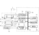
図1は、本発明の参考となる実施の形態の情報処理装置1の電気的構成を示すブロック図である。情報処理装置1は、たとえば机に設けられ、種々の物体33(図3参照)が机上に配置されると、物体33が配置された位置に応じて、出力する音を制御するように構成されている。情報処理装置1は、入力・表示系2と制御系3とを有する。入力・表示系2は、液晶ディスプレイ(Liquid Crystal Display;略称:LCD)5、センサ6、内蔵カメラ7、光源であるバックライト8および複数のスピーカ30を有する。制御系3は、制御手段である中央演算処理装置(Central Processing Unit;略称:CPU)10、センサ入力部11、周辺機器入力部12、表示制御部13、主記憶部14、補助記憶部15、通信部16、バス17および音声制御部31を有する。 FIG. 1 is a block diagram showing an electrical configuration of an information processing apparatus 1 according to an embodiment which is a reference of the present invention. The information processing apparatus 1 is provided on a desk, for example, and is configured to control the sound to be output according to the position where the object 33 is placed when various objects 33 (see FIG. 3) are placed on the desk. ing. The information processing apparatus 1 includes an input / display system 2 and a control system 3. The input / display system 2 includes a liquid crystal display (LCD) 5, a sensor 6, a built-in camera 7, a backlight 8 as a light source, and a plurality of speakers 30. The control system 3 includes a central processing unit (abbreviation: CPU) 10, which is a control means, a sensor input unit 11, a peripheral device input unit 12, a display control unit 13, a main storage unit 14, an auxiliary storage unit 15, The communication unit 16, the bus 17, and the voice control unit 31 are included.

LCD5は、表示手段であって、その表示部32(図3参照)に、電子ファイルなどの情報を画像として表示する。センサ6は、LCD5の表示画面上に載置される物体33、文字およびダグの少なくともいずれか一つのパターンを検出する。表示部32は、物体33を載置可能に構成され、机として用いることが可能な強度を有する。   The LCD 5 is a display means, and displays information such as an electronic file as an image on the display unit 32 (see FIG. 3). The sensor 6 detects at least one pattern of the object 33, characters, and doug placed on the display screen of the LCD 5. The display unit 32 is configured to be able to place the object 33 and has a strength that can be used as a desk.

センサ6は、薄膜トランジスタ(Thin Film Transistor;略称:TFT)アレイを用いたイメージセンサ、赤外線センサ、デジタイザ、タブレットなどによって実現される。センサ6は、低解像度のセンサと高解像度のセンサとを個別に構成してもよいし、一体形で構成してもよい。内蔵カメラ7は、表示画面上に載置される物体33、文字およびデータキャリアの少なくともいずれか一つのパターンを検出する。データキャリアは、たとえばQRコードおよびバーコードなどであり、このようなデータキャリアが物体33に形成されていないかを内蔵カメラ7は検出する機能を有する。内蔵カメラ7は、センサ6と一体形で構成してもよい。センサ6または内蔵カメラ7は、位置検出手段としての機能を有し、表示部32上の物体33の位置を検出し、検出した位置情報をセンサ入力部11に与える。   The sensor 6 is realized by an image sensor, an infrared sensor, a digitizer, a tablet, or the like using a thin film transistor (abbreviation: TFT) array. The sensor 6 may include a low-resolution sensor and a high-resolution sensor individually, or may be configured in an integrated manner. The built-in camera 7 detects at least one pattern of the object 33, characters, and data carrier placed on the display screen. The data carrier is, for example, a QR code and a barcode, and the built-in camera 7 has a function of detecting whether such a data carrier is formed on the object 33. The built-in camera 7 may be configured integrally with the sensor 6. The sensor 6 or the built-in camera 7 has a function as a position detection unit, detects the position of the object 33 on the display unit 32, and gives the detected position information to the sensor input unit 11.

バックライト8は、液晶表示を行うための光源となる。光源としては、バックライト8に限らず、LCD5が反射形で構成される場合は、フロントライト方式であってもよい。スピーカ30は、音出力手段であって、音を出力する。スピーカ30は、本実施の形態では、複数設けられ、各スピーカ30a〜30dが音出力部として機能する。各スピーカ30a〜30dは、個別に制御可能に構成される。センサ入力部11には、センサ6および内蔵カメラ7が電気的に接続されている。センサ入力部11は、センサ6および内蔵カメラ7からの出力を電気信号に変換してデータ化する。周辺機器入力部12には、キーボード、ポインティングデバイス、外部カメラ、マイクロフォンなどの周辺機器18がそれぞれ電気的に接続可能に構成されている。周辺機器入力部12は、周辺機器18からの出力を電気信号に変換してデータ化する。   The backlight 8 serves as a light source for performing liquid crystal display. The light source is not limited to the backlight 8 and may be a front light system when the LCD 5 is configured in a reflective form. The speaker 30 is sound output means and outputs sound. In the present embodiment, a plurality of speakers 30 are provided, and each of the speakers 30a to 30d functions as a sound output unit. Each speaker 30a-30d is comprised so that control is possible individually. The sensor input unit 11 is electrically connected to the sensor 6 and the built-in camera 7. The sensor input unit 11 converts the outputs from the sensor 6 and the built-in camera 7 into electric signals and converts them into data. Peripheral devices 18 such as a keyboard, a pointing device, an external camera, and a microphone can be electrically connected to the peripheral device input unit 12. The peripheral device input unit 12 converts the output from the peripheral device 18 into an electrical signal and converts it into data.

表示制御部13には、LCD5およびバックライト8が電気的に接続されている。表示制御部13は、CPU10からの指令に従って、LCD5およびバックライト8を制御する。音声制御部31には、各スピーカ30a〜30dが電気的に接続されている。音声制御部31は、CPU10からの指令に従って、各スピーカ30a〜30dを個別に制御する。   The LCD 5 and the backlight 8 are electrically connected to the display control unit 13. The display control unit 13 controls the LCD 5 and the backlight 8 according to a command from the CPU 10. The speakers 30 a to 30 d are electrically connected to the sound control unit 31. The voice control unit 31 individually controls each of the speakers 30a to 30d according to a command from the CPU 10.

主記憶部14には、情報処理装置1における複数の処理動作を実現させるために必要な動作プログラムが記憶されている。主記憶部14は、たとえばランダムアクセスメモリ
(Random Access Memory:略称RAM)によって実現され、補助記憶部15に記憶される情報を取得し、または各構成から伝送された情報を、一時的に記憶する。補助記憶部15は、ハードディスク、デジタル多機能ディスク(Digital Versatile Disc;略称:DVD)およびコンパクトディスク(Compact Disk:略称CD)などの情報記憶媒体によって実現される。補助記憶部15には、補助的に動作に必要な情報が記憶される。また補助記憶部15は、関連音情報記憶手段としての機能を有し、本実施の形態では物体33を識別する識別情報に関連付けられて関連音情報が記憶されている。また補助記憶部15には、表示部32に表示される画像に関連付けられて関連音情報が記憶されている。関連音情報は、たとえば物体33および画像に関連する音情報である。たとえば物体33が機関車の模型(以下、単に「機関車」ということがある)である場合、関連音情報は機関車が走行するときに生じる音に関する情報であり、またたとえば物体33が飛行機の模型(以下、単に「飛行機」ということがある)である場合、関連音情報は飛行機が飛行するときに生じる音に関する情報である。また画像が林41を示す画像である場合、関連音情報は林41にて生じる鳥の鳴き声、または風が通過する音に関する情報である。通信部16は、インターネット回線網、公衆回線網およびLAN(Local Area Network)などの通信回線網に電気的に接続され、外部の機器と通信する機能を有する。
The main storage unit 14 stores an operation program necessary for realizing a plurality of processing operations in the information processing apparatus 1. The main storage unit 14 is realized by, for example, a random access memory (abbreviated as RAM) and acquires information stored in the auxiliary storage unit 15 or temporarily stores information transmitted from each configuration. . The auxiliary storage unit 15 is realized by an information storage medium such as a hard disk, a digital multifunctional disc (abbreviation: DVD), and a compact disc (abbreviation: CD). The auxiliary storage unit 15 stores information necessary for the operation in an auxiliary manner. The auxiliary storage unit 15 has a function as a related sound information storage unit, and in the present embodiment, related sound information is stored in association with identification information for identifying the object 33. The auxiliary storage unit 15 stores related sound information in association with the image displayed on the display unit 32. The related sound information is sound information related to the object 33 and the image, for example. For example, when the object 33 is a model of a locomotive (hereinafter, sometimes simply referred to as “locomotive”), the related sound information is information related to a sound generated when the locomotive travels. In the case of a model (hereinafter, sometimes simply referred to as “airplane”), the related sound information is information regarding sound generated when the airplane flies. Further, when the image is an image showing the forest 41, the related sound information is information related to a sound of a bird cry or a wind passing through the forest 41. The communication unit 16 is electrically connected to a communication line network such as an Internet line network, a public line network, and a LAN (Local Area Network), and has a function of communicating with an external device.

CPU10は、バス17を介して、センサ入力部11、周辺機器入力部12、表示制御部13、主記憶部14、補助記憶部15、通信部16および音声制御部31と電気的に接続されている。CPU10は、その内部におよび主記憶部14に記憶される制御プログラムに基づいて、センサ入力部11、周辺機器入力部12、表示制御部13、主記憶部14、補助記憶部15、通信部16および音声制御部31を含むハードウェア資源を統括的に制御する。CPU10は、たとえばマイクロコンピュータによって実現される。   The CPU 10 is electrically connected to the sensor input unit 11, the peripheral device input unit 12, the display control unit 13, the main storage unit 14, the auxiliary storage unit 15, the communication unit 16, and the voice control unit 31 via the bus 17. Yes. The CPU 10 includes a sensor input unit 11, a peripheral device input unit 12, a display control unit 13, a main storage unit 14, an auxiliary storage unit 15, and a communication unit 16 based on a control program stored therein and in the main storage unit 14. And the hardware resources including the voice control unit 31 are comprehensively controlled. The CPU 10 is realized by a microcomputer, for example.

またCPU10は、センサ6または内蔵カメラ7によって検出される物体33の位置に対応する音を出力するように、音声制御部31に指令を与え、各スピーカ30a〜30dを制御する。またCPU10は、センサ6または内蔵カメラ7によって検出される物体33の位置に基づいて、各スピーカ30a〜30dから出力する音を個別に制御する。ここで音を制御するとは、たとえば音の性状を制御することである。音の性状とは、各スピーカ30a〜30dで出力される音の出力状態、および音の特性の少なくとも1つを含む。また音の出力状態は、音量、音の高低および音質のうち、少なくとも1つを含む。また音の特性は、操作者の嗜好度合、種類およびジャンルの少なくとも1つを含む。   Further, the CPU 10 gives a command to the audio control unit 31 so as to output a sound corresponding to the position of the object 33 detected by the sensor 6 or the built-in camera 7 and controls the speakers 30a to 30d. The CPU 10 individually controls sounds output from the speakers 30 a to 30 d based on the position of the object 33 detected by the sensor 6 or the built-in camera 7. Here, controlling the sound means, for example, controlling the properties of the sound. The sound property includes at least one of a sound output state output from each of the speakers 30a to 30d and a sound characteristic. The sound output state includes at least one of volume, sound level, and sound quality. The sound characteristics include at least one of the operator's preference level, type, and genre.

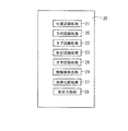
図2は、主記憶部14に記憶される動作プログラム20の構成を示す図である。本実施の形態の動作プログラム20は、位置認識処理プログラム21、方向認識処理プログラム25、タグ認識処理プログラム22、形状認識処理プログラム23、文字認識処理プログラム26、情報検索処理プログラム24、画像比較処理プログラム27および音出力処理プログラム28を含む。CPU10が位置認識処理プログラム21を実行することによって、センサ6または内蔵カメラ7によって検出された物体33の位置を認識する位置認識処理が実現される。物体33の位置とは、たとえば表示部32の表示領域32aの予め定められる位置を原点とし、物体33の原点に最も近い部分の位置座標を認識する。原点は、たとえば後述する図3において表示領域32aの左下の位置が設定される。   FIG. 2 is a diagram showing a configuration of the operation program 20 stored in the main storage unit 14. The operation program 20 of the present embodiment includes a position recognition processing program 21, a direction recognition processing program 25, a tag recognition processing program 22, a shape recognition processing program 23, a character recognition processing program 26, an information search processing program 24, and an image comparison processing program. 27 and a sound output processing program 28. When the CPU 10 executes the position recognition processing program 21, position recognition processing for recognizing the position of the object 33 detected by the sensor 6 or the built-in camera 7 is realized. With respect to the position of the object 33, for example, a predetermined position of the display area 32a of the display unit 32 is set as the origin, and the position coordinates of the portion closest to the origin of the object 33 are recognized. The origin is set, for example, at the lower left position of the display area 32a in FIG.

CPU10がタグ認識処理プログラム22を実行することによって、センサ6または内蔵カメラ7によって検出されたデータキャリアに基づくタグ情報を認識する。データキャリアは、たとえばQRコードおよびバーコードなどである。タグ情報には、たとえば識別情報、方向認識情報および形状認識情報などの情報が含まれる。識別情報は、物体33を識別するための情報であり、方向認識情報は、物体33の向きを認識するための情報であり、形状認識情報は、物体33の形状を認識するための情報である。したがってCPU10は、物体33を識別する識別手段としての機能を有する。   When the CPU 10 executes the tag recognition processing program 22, tag information based on the data carrier detected by the sensor 6 or the built-in camera 7 is recognized. The data carrier is, for example, a QR code and a barcode. The tag information includes information such as identification information, direction recognition information, and shape recognition information. The identification information is information for identifying the object 33, the direction recognition information is information for recognizing the direction of the object 33, and the shape recognition information is information for recognizing the shape of the object 33. . Therefore, the CPU 10 has a function as identification means for identifying the object 33.

CPU10が形状認識処理プログラム23を実行することによって、センサ6または内蔵カメラ7で読取られた画像の形状を認識する。CPU10が情報検索処理プログラム24を実行することによって、識別情報に関連付けられる関連音情報を補助記憶部15から検索する。CPU10が文字認識処理プログラム26を実行することによって、センサ6または内蔵カメラ7によって検出された文字情報を認識する。CPU10が方向認識処理プログラム25を実行することによって、画像情報、データキャリアに含まれる方向認識情報または認識された文字に基づいて、物体33の予め定められる方向、たとえば上下方向または左右方向を認識する。CPU10が画像比較処理プログラム27を実行することによって、時系列の画像情報の比較を行う画像比較処理が実現される。CPU10が音出力処理プログラム28を実行することによって、位置認識処理によって認識される物体33の位置に基づいて、各スピーカ30a〜30dが出力する音を制御する音出力処理が実現される。   The CPU 10 recognizes the shape of the image read by the sensor 6 or the built-in camera 7 by executing the shape recognition processing program 23. The CPU 10 searches the auxiliary storage unit 15 for related sound information associated with the identification information by executing the information search processing program 24. When the CPU 10 executes the character recognition processing program 26, the character information detected by the sensor 6 or the built-in camera 7 is recognized. When the CPU 10 executes the direction recognition processing program 25, the predetermined direction of the object 33, for example, the vertical direction or the horizontal direction is recognized based on the image information, the direction recognition information included in the data carrier or the recognized character. . When the CPU 10 executes the image comparison processing program 27, an image comparison process for comparing time-series image information is realized. When the CPU 10 executes the sound output processing program 28, sound output processing for controlling the sound output from each of the speakers 30a to 30d is realized based on the position of the object 33 recognized by the position recognition processing.

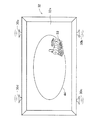
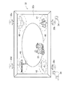
図3は、情報処理装置1を示す正面図であって、表示部32に表示される画面の一例を示す図である。表示部32は、四角形状であって、四角形状の画像を表示する表示領域32aを表面部分に有する。表示部32は、その4つの角部付近に、4つのスピーカ30a〜30dがそれぞれ設けられる。図3では、物体33として機関車が表示部32に載置されている状態を示す。本実施の形態では、上下方向を、図3において紙面上下方向とし、左右方向は、図3において紙面左右方向とする。表示部32の中心付近を中心とする楕円状の線路の画像が、各角部を近接するように表示される。また図3では、物体33として機関車が、右下の角部付近に載置される。   FIG. 3 is a front view illustrating the information processing apparatus 1 and is a diagram illustrating an example of a screen displayed on the display unit 32. The display unit 32 has a quadrangular shape, and has a display region 32a for displaying a quadrangular image on the surface portion. The display unit 32 is provided with four speakers 30a to 30d in the vicinity of the four corners. FIG. 3 shows a state where the locomotive is placed on the display unit 32 as the object 33. In the present embodiment, the vertical direction is the vertical direction in FIG. 3, and the horizontal direction is the horizontal direction in FIG. An image of an elliptical line centered around the center of the display unit 32 is displayed so that the corners are close to each other. In FIG. 3, the locomotive is placed as the object 33 in the vicinity of the lower right corner.

図4は、情報処理装置1を示す正面図であって、表示部32に表示される画面の一例を示す図であり、スピーカ30から音が出力されている状態を示す。図4では、理解を容易にするため、右下のスピーカ30bから音が出力されている状態を、音符34にて可視化して示す。したがって図4では、右下のスピーカ30bからのみ音が出力され、残余の3つのスピーカ30a,30c,30dからは音は出力されていない。このような音を出力するスピーカ30の選択は、表示部32に配置する物体33である機関車の位置に対応している。本実施の形態では、表示部32に配置される物体33から最も近いスピーカ30のみから音を出力するようにCPU10によって制御される。このような処理に関して、フローチャートを用いて説明する。   FIG. 4 is a front view showing the information processing apparatus 1, and is a diagram showing an example of a screen displayed on the display unit 32, and shows a state where sound is output from the speaker 30. In FIG. 4, in order to facilitate understanding, a state in which sound is output from the lower right speaker 30 b is visualized and shown as a note 34. Therefore, in FIG. 4, sound is output only from the lower right speaker 30b, and no sound is output from the remaining three speakers 30a, 30c, and 30d. The selection of the speaker 30 that outputs such a sound corresponds to the position of the locomotive that is the object 33 arranged on the display unit 32. In the present embodiment, the CPU 10 controls to output sound only from the speaker 30 closest to the object 33 arranged on the display unit 32. Such processing will be described using a flowchart.

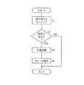
図5は、CPU10の音出力処理手順を示すフローチャートである。図5に示す音出力処理は、CPU10によって実行される。図5に示す音出力処理は、情報処理装置1の動作中に繰返し実行される。情報処理装置1の動作中は、表示部32には何らかの画像が表示され、たとえば図4に示す画像が表示される。図5に示す処理は、たとえば情報処理装置1の図示外の主電源をオフからオンにする条件、図示外のタイマーによる一定時間間隔、図示外の人感センサなどによる利用者の接近もしくは動きを検知した条件において、開始される。   FIG. 5 is a flowchart showing the sound output processing procedure of the CPU 10. The sound output process shown in FIG. The sound output process shown in FIG. 5 is repeatedly executed during the operation of the information processing apparatus 1. During the operation of the information processing apparatus 1, some image is displayed on the display unit 32, for example, the image shown in FIG. 4 is displayed. The processing shown in FIG. 5 includes, for example, conditions for turning off an unillustrated main power source of the information processing apparatus 1, a fixed time interval by an unillustrated timer, an approach or movement of a user by an unillustrated human sensor or the like. It is started in the detected condition.

ステップa1では、次のステップa2で物体33があるか否かを判断すべく、情報処理装置1の表示手段であるLCD5の表示画面上の状態をセンサ6または内蔵カメラ7でセンシングして、ステップa2に移る。ステップa2では、前記センシングの結果、LCD5の表示画面上に物体33があるか否かを判断し、表示画面上に物体33があると判断されるとステップa3に移り、表示画面上に物体33がないと判断されると本処理を終了する。   In step a1, in order to determine whether or not the object 33 is present in the next step a2, the state on the display screen of the LCD 5 which is the display means of the information processing apparatus 1 is sensed by the sensor 6 or the built-in camera 7, and the step Move to a2. In step a2, it is determined whether or not the object 33 is present on the display screen of the LCD 5 as a result of the sensing. If it is determined that the object 33 is present on the display screen, the process proceeds to step a3 and the object 33 is displayed on the display screen. If it is determined that there is no, this process is terminated.

ステップa3では、前述の位置認識処理プログラム21を実行することによって、物体33の位置を認識して、ステップa4に移る。したがってステップa1〜a3は、表示画面上の物体33の位置を検出する位置検出工程である。ステップa4では、前述の音出力処理プログラム28を実行することによって、物体33の位置に基づいて、最も近接するスピーカ30を選択し、選択されたスピーカ30から音を出力するように音声制御部31に指令を与え、本処理を終了する。したがってステップa4は、検出される物体の位置に対応する音を出力する音出力工程である。   In step a3, the position recognition processing program 21 is executed to recognize the position of the object 33, and the process proceeds to step a4. Accordingly, steps a1 to a3 are position detection steps for detecting the position of the object 33 on the display screen. In step a4, by executing the sound output processing program 28 described above, the closest speaker 30 is selected based on the position of the object 33, and the sound control unit 31 is configured to output sound from the selected speaker 30. A command is given to, and this processing is terminated. Therefore, step a4 is a sound output process for outputting a sound corresponding to the position of the detected object.

このような処理によって、表示部32に物体33あると、その物体33の表示部32上の位置に対応する音がスピーカ30によって出力されるので、物体33の位置を変更することによって出力される音を制御することができる。これによって操作者は、表示部32上の物体33の位置を変更して、出力される音を制御することができるので、音の出力を直感的に操作して制御することができる。したがってスピーカ30から出力される音の操作性を向上することができる。   By such processing, if there is an object 33 on the display unit 32, a sound corresponding to the position of the object 33 on the display unit 32 is output by the speaker 30, so that it is output by changing the position of the object 33. The sound can be controlled. As a result, the operator can change the position of the object 33 on the display unit 32 and control the output sound, so that the output of the sound can be intuitively operated and controlled. Therefore, the operability of the sound output from the speaker 30 can be improved.

また本実施の形態では、センサ6または内蔵カメラ7によって検出される物体33の位置に基づいて、各スピーカ30a〜30dから出力する音の性状がCPU10によって個別に制御される。したがって物体33の位置を変更することによって、各スピーカ30a〜30dから出力される音の性状を個別に制御することができる。これによって操作者は、物体33の位置を変更して、各スピーカ30a〜30dから出力される音の性状を制御することができるので、各スピーカ30a〜30dの音の出力を直感的に制御することができる。また複数のスピーカ30を含むので、臨場感のある音を出力することができる。   In the present embodiment, the CPU 10 individually controls the properties of sounds output from the speakers 30 a to 30 d based on the position of the object 33 detected by the sensor 6 or the built-in camera 7. Therefore, by changing the position of the object 33, the properties of the sounds output from the speakers 30a to 30d can be individually controlled. Thus, the operator can change the position of the object 33 and control the sound properties output from the speakers 30a to 30d, and thus intuitively control the sound output of the speakers 30a to 30d. be able to. In addition, since a plurality of speakers 30 are included, a realistic sound can be output.

また本実施の形態では、音の性状として、音の出力情報である音の大小が選択可能である。したがって物体33に最も近接するスピーカ30の音を大きくし、残余のスピーカ30から出力される音を可及的に小さく、換言すると音の出力が停止される。したがって音を出力したいスピーカ30の近くに物体33を配置することによって、音を出力するスピーカ30を選択することができるので、操作者は直感的な操作でスピーカ30を操作することができる。   In the present embodiment, the magnitude of the sound, which is the sound output information, can be selected as the sound property. Therefore, the sound of the speaker 30 closest to the object 33 is increased, and the sound output from the remaining speakers 30 is reduced as much as possible, in other words, the sound output is stopped. Therefore, by arranging the object 33 near the speaker 30 that wants to output sound, the speaker 30 that outputs sound can be selected, so that the operator can operate the speaker 30 by intuitive operation.

また本実施の形態では、各スピーカ30a〜30dから出力される音は特に限定せず、音を出力するスピーカ30を選択する構成に関して説明したが、表示部32に配置された物体33に基づく音を出力するのようにしてもよい。CPU10は、前述のステップa3にて、位置認識処理プログラムと並行して、タグ認識処理プログラムを実行し、物体33の識別情報を取得する。この識別情報に基づいて、情報検索処理プログラムを実行し、関連付けて補助記憶部15に記憶される関連音情報を読み出す。この読み出した関連音情報を、ステップa4にて出力するように音声制御部31に指令を与える。このような処理によって、物体33に関連する音を出力することができる。たとえば物体33が、図4に示すように、機関車である場合、出力される音は、前述したように機関車が走行するときに生じる音である。このように物体33に関連する音を出力し、さらに物体33に近接するスピーカ30から音を出力することによって、表示部32上のシーンにおいて物体33があたかもその位置にあるかのような臨場感を得ることができる。   In the present embodiment, the sound output from each of the speakers 30a to 30d is not particularly limited, and the configuration for selecting the speaker 30 that outputs sound has been described. However, the sound based on the object 33 arranged on the display unit 32 is described. May be output. In step a3 described above, the CPU 10 executes the tag recognition processing program in parallel with the position recognition processing program, and acquires the identification information of the object 33. Based on this identification information, an information search processing program is executed, and related sound information stored in the auxiliary storage unit 15 in association with it is read out. A command is given to the voice control unit 31 so as to output the read related sound information in step a4. By such processing, a sound related to the object 33 can be output. For example, when the object 33 is a locomotive as shown in FIG. 4, the output sound is a sound generated when the locomotive travels as described above. Thus, by outputting the sound related to the object 33 and further outputting the sound from the speaker 30 close to the object 33, the presence of the object 33 as if in the position in the scene on the display unit 32. Can be obtained.

次に本発明の第の実施の形態に関して説明する。本実施の形態の情報処理装置1では、物体33が表示部32に配置されると、その物体33に関連する音と、その物体33が配置された位置またはその近傍に表示部32に表示されている画像に関連する音が出力される点に特徴を有する。図6は、情報処理装置1を示す正面図であって、本実施の形態の表示部32に表示される画面の一例を示す図である。図6では、表示部32に表示される画像として、4つの角部付近に、時計周りに順次、雨雲40、林41、湖畔42、および市街地43が、一例として表示される。したがって表示部32には、右上の角部付近に雨雲40の画像が表示され、右下の角部付近に林41の画像が表示され、左下の角部付近に湖畔42の画像が表示され、左上の角部付近に市街地43の画像が表示される。また表示部32の中心付近を中心とする楕円状の線路44の画像が、各角部を近接するように表示される。また図3では、物体33として機関車が、林41の画像が表示されている付近に載置される。 Next, a first embodiment of the present invention will be described. In the information processing apparatus 1 according to the present embodiment, when the object 33 is arranged on the display unit 32, the sound related to the object 33 is displayed on the display unit 32 at or near the position where the object 33 is arranged. It is characterized in that sound related to the current image is output. FIG. 6 is a front view illustrating the information processing apparatus 1 and is a diagram illustrating an example of a screen displayed on the display unit 32 of the present embodiment. In FIG. 6, as an image displayed on the display unit 32, rain clouds 40, forests 41, lakesides 42, and a city area 43 are sequentially displayed as an example in the vicinity of the four corners in the clockwise direction. Therefore, on the display unit 32, an image of the rain cloud 40 is displayed near the upper right corner, an image of the forest 41 is displayed near the lower right corner, and an image of the lake shore 42 is displayed near the lower left corner, An image of the urban area 43 is displayed near the upper left corner. In addition, an image of an elliptical line 44 centered around the center of the display unit 32 is displayed so that the corners are close to each other. In FIG. 3, the locomotive is placed as the object 33 in the vicinity where the image of the forest 41 is displayed.

図7は、情報処理装置1を示す正面図であって、本実施の形態の表示部32に表示される画面の一例を示す図であり、スピーカ30から音が出力されている状態を示す。図7では、理解を容易にするため、右下のスピーカ30bから音が出力されている状態を、音符34にて可視化して示す。したがって図7では、右下のスピーカ30bからのみ音が出力され、残余の3つのスピーカ30a,30c,30dからは音は出力されていない。このような音を出力するスピーカ30の選択は、表示部32に配置する物体33である機関車の位置に対応している。本実施の形態では、表示部32に配置される物体33から最も近いスピーカ30のみから音を出力するようにCPU10によって制御される。また最も近いスピーカ30から出力される音は、物体33に関連する音、および物体33が載置される位置またはその近傍に表示される画像に関連する音が出力される。したがって図7に示すように、物体33は機関車であり、物体33が載置される近傍には林41が表示されるので、右下のスピーカ30bからは、機関車が走行するときに生じる音と、林41にて生じる音が出力される。このような処理に関して、フローチャートを用いて説明する。   FIG. 7 is a front view showing the information processing apparatus 1, and is a diagram showing an example of a screen displayed on the display unit 32 of the present embodiment, and shows a state where sound is output from the speaker 30. In FIG. 7, in order to facilitate understanding, a state in which sound is output from the lower right speaker 30 b is visualized and shown as a note 34. Therefore, in FIG. 7, sound is output only from the lower right speaker 30b, and no sound is output from the remaining three speakers 30a, 30c, and 30d. The selection of the speaker 30 that outputs such a sound corresponds to the position of the locomotive that is the object 33 arranged on the display unit 32. In the present embodiment, the CPU 10 controls to output sound only from the speaker 30 closest to the object 33 arranged on the display unit 32. The sound output from the nearest speaker 30 is a sound related to the object 33 and a sound related to an image displayed at or near the position where the object 33 is placed. Therefore, as shown in FIG. 7, the object 33 is a locomotive, and a forest 41 is displayed in the vicinity where the object 33 is placed, so that the locomotive travels from the lower right speaker 30 b. Sound and sound generated in the forest 41 are output. Such processing will be described using a flowchart.

図8は、CPU10の本実施の形態の音出力処理手順を示すフローチャートである。図8に示す音出力処理は、CPU10によって実行される。図8に示す音出力処理は、情報処理装置1の動作中に繰返し実行される。たとえば情報処理装置1の図示外の主電源をオフからオンにする条件、図示外のタイマーによる一定時間間隔、図示外の人感センサなどによる利用者の接近もしくは動きを検知した条件において、図8に示す処理が開始される。   FIG. 8 is a flowchart showing the sound output processing procedure of the present embodiment of the CPU 10. The sound output process shown in FIG. 8 is executed by the CPU 10. The sound output process shown in FIG. 8 is repeatedly executed during the operation of the information processing apparatus 1. For example, in the condition that the main power source (not shown) of the information processing apparatus 1 is turned on from off, the constant time interval by a timer (not shown), and the condition of detecting the approach or movement of the user by a human sensor (not shown), The process shown in FIG.

ステップb1では、次のステップb2で物体33があるか否かを判断すべく、情報処理装置1の表示手段であるLCD5の表示画面上の状態をセンサ6または内蔵カメラ7でセンシングして、ステップb2に移る。ステップb2では、前記センシングの結果、LCD5の表示画面上に物体33があるか否かを判断し、表示画面上に物体33があると判断されるとステップb3に移り、表示画面上に物体33がないと判断されると本処理を終了する。   In step b1, in order to determine whether or not the object 33 is present in the next step b2, the state on the display screen of the LCD 5, which is the display means of the information processing apparatus 1, is sensed by the sensor 6 or the built-in camera 7, Move to b2. In step b2, as a result of the sensing, it is determined whether or not there is an object 33 on the display screen of the LCD 5. If it is determined that there is the object 33 on the display screen, the process proceeds to step b3 and the object 33 is displayed on the display screen. If it is determined that there is no, this process is terminated.

ステップb3では、前述の位置認識処理プログラム21を実行することによって、物体33の位置を認識して、ステップb4に移る。ステップb4では、前述の音出力処理プログラム28を実行することによって、物体33の位置に基づいて、最も近接するスピーカ30を選択し、ステップb5に移る。ステップb5では、出力する音を決定し、選択されたスピーカ30から決定した音を出力するように音声制御部31に指令を与え、本処理を終了する。このステップb5では、タグ認識処理プログラムを実行し、物体33の識別情報を取得する。この識別情報に基づいて、情報検索処理プログラムを実行し、識別情報に関連付けて補助記憶部15に記憶される関連音情報を読み出す。また物体33の位置に表示される画像に基づいて、情報検索処理プログラムを実行し、画像に関連付けて補助記憶部15に記憶される関連音情報を読み出す。このような関連音情報を出力する音に決定する。このように物体33に関連する音、および物体33が配置される音を出力し、さらに物体33に近接するスピーカ30から音を出力することによって、表示部32上のシーンにおいて物体33があたかもその位置にあるかのような臨場感を得ることができる。   In step b3, the position recognition processing program 21 is executed to recognize the position of the object 33, and the process proceeds to step b4. In step b4, by executing the sound output processing program 28 described above, the closest speaker 30 is selected based on the position of the object 33, and the process proceeds to step b5. In step b5, the sound to be output is determined, a command is given to the voice control unit 31 so as to output the determined sound from the selected speaker 30, and this process is terminated. In this step b5, the tag recognition processing program is executed, and the identification information of the object 33 is acquired. Based on this identification information, an information search processing program is executed to read related sound information stored in the auxiliary storage unit 15 in association with the identification information. Further, based on the image displayed at the position of the object 33, an information search processing program is executed to read related sound information stored in the auxiliary storage unit 15 in association with the image. The sound to output such related sound information is determined. In this way, by outputting the sound related to the object 33 and the sound at which the object 33 is arranged, and further outputting the sound from the speaker 30 close to the object 33, the object 33 is as if in the scene on the display unit 32. You can get a sense of presence as if you were in a position.

したがって本実施の形態では、センサ6または内蔵カメラ7によって検出される物体33の位置に表示される画像に基づいて、各スピーカ30a〜30dから出力する音の性状がCPU10によって個別に制御される。したがって表示部32上の異なる画像が表示される位置に物体33の位置を変更して、各スピーカ30a〜30dから出力される音の性状を個別に制御することができる。これによって操作者は、物体33の位置を表示部32に表示される画像の位置に変更して、各スピーカ30a〜30dから出力される音の性状を制御することができるので、各スピーカ30a〜30dの音の出力をより直感的に制御することができる。また複数のスピーカ30を含むので、臨場感のある音を出力することができる。   Therefore, in the present embodiment, the sound properties output from the speakers 30a to 30d are individually controlled by the CPU 10 based on the image displayed at the position of the object 33 detected by the sensor 6 or the built-in camera 7. Therefore, the position of the object 33 can be changed to a position where a different image is displayed on the display unit 32, and the sound properties output from the speakers 30a to 30d can be individually controlled. Accordingly, the operator can change the position of the object 33 to the position of the image displayed on the display unit 32 and control the properties of the sound output from the speakers 30a to 30d. The output of the 30d sound can be controlled more intuitively. In addition, since a plurality of speakers 30 are included, a realistic sound can be output.

また本実施の形態では、表示上の物体33に関連する音が各スピーカ30a〜30dから個別に出力可能であるので、操作者は、物体33を別の物体33に変更することによって、各スピーカ30a〜30dから出力される音を変更することができる。これによって操作者は、物体33そのものを変更し、また物体33の表示部32上の位置を変更することによって、出力される音を変更することができる。したがって操作者は、より直感的にスピーカ30を個別に制御することができるので、操作性をさらに向上することができる。   In the present embodiment, since sounds related to the object 33 on the display can be individually output from the speakers 30 a to 30 d, the operator changes the object 33 to another object 33 to change each speaker. The sound output from 30a-30d can be changed. Accordingly, the operator can change the sound to be output by changing the object 33 itself and changing the position of the object 33 on the display unit 32. Therefore, since the operator can control the speakers 30 individually more intuitively, the operability can be further improved.

次に本発明の第の実施の形態に関して説明する。本実施の形態の情報処理装置1では、物体33が表示部32に配置されると、その物体33が配置された位置またはその近傍に表示部32に表示されている画像に基づく音が出力される点に特徴を有する。 Next will be described a second embodiment of the present invention. In the information processing apparatus 1 according to the present embodiment, when the object 33 is disposed on the display unit 32, a sound based on the image displayed on the display unit 32 is output at or near the position where the object 33 is disposed. It has a feature in that.

図9は、情報処理装置1を示す正面図であって、本実施の形態の表示部32に表示される画面の一例を示す図である。図9では、表示部32に表示される画像として、表示領域32aが2行2列に4分割され、各表示領域32aに異なる楽器の画像がそれぞれ表示される。本実施の形態では、図9に示すように、右上の表示領域32aにピアノ45の画像が表示され、右下の表示領域32aにトランペット46の画像が表示され、左下の表示領域32aに太鼓47の画像が表示され、左上の表示領域32aにギター48の画像が表示される。また表示部32の中心付近を中心とする円状の領域49を示す画像が表示される。   FIG. 9 is a front view showing the information processing apparatus 1 and is a diagram showing an example of a screen displayed on the display unit 32 of the present embodiment. In FIG. 9, as an image displayed on the display unit 32, a display area 32a is divided into four in two rows and two columns, and images of different instruments are displayed in the respective display areas 32a. In the present embodiment, as shown in FIG. 9, the image of the piano 45 is displayed in the upper right display area 32a, the image of the trumpet 46 is displayed in the lower right display area 32a, and the drum 47 is displayed in the lower left display area 32a. The image of the guitar 48 is displayed in the display area 32a in the upper left. Further, an image showing a circular region 49 centered around the center of the display unit 32 is displayed.

図10は、情報処理装置1を示す正面図であって、図9に示す表示部32に表示される画面の一例を示す図であり、スピーカ30から音が出力されている状態を示す。図10では、理解を容易にするため、右上のスピーカ30aから音が出力されている状態を、音符34にて可視化して示す。したがって図10では、右上のスピーカ30aからのみ音が出力され、残余の3つのスピーカ30b,30c,30dからは音は出力されていない。また図10では、物体33として指差しが、右上のピアノ45の画像が表示されている表示領域32aに載置される。このような音を出力するスピーカ30の選択は、表示部32に配置する物体33の位置に対応している。本実施の形態では、表示部32に配置される物体33から最も近いスピーカ30のみから音を出力するようにCPU10によって制御される。また最も近いスピーカ30から出力される音は、物体33が載置される位置またはその近傍に表示される画像に関連する音が出力される。したがって図10に示すように、物体33が載置される表示領域32aにはピアノ45が表示されるので、右上のスピーカ30aからは、ピアノ45を演奏したときの音が出力される。   FIG. 10 is a front view illustrating the information processing apparatus 1 and is a diagram illustrating an example of a screen displayed on the display unit 32 illustrated in FIG. 9, and illustrates a state in which sound is output from the speaker 30. In FIG. 10, in order to facilitate understanding, a state in which sound is output from the upper right speaker 30 a is visualized and shown as a note 34. Therefore, in FIG. 10, sound is output only from the upper right speaker 30a, and no sound is output from the remaining three speakers 30b, 30c, and 30d. Further, in FIG. 10, the pointing hand as the object 33 is placed on the display area 32 a where the image of the upper right piano 45 is displayed. The selection of the speaker 30 that outputs such a sound corresponds to the position of the object 33 arranged on the display unit 32. In the present embodiment, the CPU 10 controls to output sound only from the speaker 30 closest to the object 33 arranged on the display unit 32. The sound output from the nearest speaker 30 is a sound related to an image displayed at or near the position where the object 33 is placed. Therefore, as shown in FIG. 10, since the piano 45 is displayed in the display area 32a on which the object 33 is placed, the sound when the piano 45 is played is output from the upper right speaker 30a.

図11は、情報処理装置1を示す正面図であって、図9に示す表示部32に表示される画面の一例を示す図であり、スピーカ30から音が出力されている他の状態を示す。図11では、理解を容易にするため、スピーカ30から音が出力されている状態を、音符34にて可視化して示す。したがって図11では、4つスピーカ30から音が出力されている。図11に示すように、物体33として指差しは、円状の領域49を示す画像が表示されている位置に載置される。この円状の領域49に物体33を載置すると、全てのスピーカ30から音が出力するように制御される。   FIG. 11 is a front view illustrating the information processing apparatus 1 and is a diagram illustrating an example of a screen displayed on the display unit 32 illustrated in FIG. 9, and illustrating another state in which sound is output from the speaker 30. . In FIG. 11, in order to facilitate understanding, a state where sound is output from the speaker 30 is visualized and shown as a note 34. Therefore, in FIG. 11, sound is output from the four speakers 30. As shown in FIG. 11, the finger pointing as the object 33 is placed at a position where an image showing the circular region 49 is displayed. When the object 33 is placed in the circular area 49, control is performed so that sound is output from all the speakers 30.

前述したように音を出力するスピーカ30の選択は、表示部32に配置される物体33から最も近いスピーカ30のみから音を出力するようにCPU10によって制御される。図11に示すように物体33が配置された位置は、円状の領域49であり、この領域は全てのスピーカ30から略等距離にある。このような場合は、全てのスピーカ30から音を出力する指令であると判断され、各スピーカ30a〜30dから出力される音は、各スピーカ30a〜30dの位置に対応する画像に関連する音が出力される。したがって図11に示す場合では、右上のスピーカ30aからは、ピアノ45を演奏したときの音が出力される。また右下のスピーカ30bからは、トランペット46を演奏したときの音が出力される。また左下のスピーカ30cからは、太鼓47を演奏したときの音が出力される。また左上のスピーカ30dからは、ギター48を演奏したときの音が出力される。   As described above, the selection of the speaker 30 that outputs sound is controlled by the CPU 10 so that sound is output only from the speaker 30 that is closest to the object 33 arranged on the display unit 32. As shown in FIG. 11, the position where the object 33 is arranged is a circular region 49, and this region is substantially equidistant from all the speakers 30. In such a case, it is determined that the instruction is to output sound from all the speakers 30, and the sound output from each speaker 30a to 30d is a sound related to the image corresponding to the position of each speaker 30a to 30d. Is output. Therefore, in the case shown in FIG. 11, the sound when the piano 45 is played is output from the upper right speaker 30a. Further, the sound when the trumpet 46 is played is output from the lower right speaker 30b. The lower left speaker 30c outputs a sound when the drum 47 is played. Further, a sound when the guitar 48 is played is output from the upper left speaker 30d.

このような処理は、図8のフローチャートにおける処理と同様の処理によって実現される。具体的には、前述のステップb5にて、タグ認識処理プログラムを実行し、物体33の識別情報を取得する。この識別情報に基づいて、情報検索処理プログラムを実行し、識別情報に関連付けて補助記憶部15に記憶される関連音情報を読み出す。本実施の形態のように物体33が指差しである場合、関連音情報としては音を出力しない情報が記憶されている。また物体33の位置に表示される画像に基づいて、情報検索処理プログラムを実行し、画像に関連付けて補助記憶部15に記憶される関連音情報を読み出す。このような関連音情報を出力する音に決定する。これによって物体33が配置される位置に表示される画像に関連する関連音情報が音として出力される。したがって前述の各実施の形態と同様の作用および効果を達成することができる。   Such a process is realized by a process similar to the process in the flowchart of FIG. Specifically, in step b5 described above, the tag recognition processing program is executed, and the identification information of the object 33 is acquired. Based on this identification information, an information search processing program is executed to read related sound information stored in the auxiliary storage unit 15 in association with the identification information. When the object 33 is a pointing hand as in the present embodiment, information that does not output sound is stored as related sound information. Further, based on the image displayed at the position of the object 33, an information search processing program is executed to read related sound information stored in the auxiliary storage unit 15 in association with the image. The sound to output such related sound information is determined. Thereby, related sound information related to the image displayed at the position where the object 33 is arranged is output as a sound. Therefore, the same operations and effects as those of the above-described embodiments can be achieved.

また本実施の形態では、物体33は指差しであるが、このような指差しに限らず、たとえば関連音情報が関連付けて記憶される物体33であってもよい。たとえば物体33が、他の楽器、たとえばフルートの模型(以下、単に「フルート」ということがある)である場合、フルートをトランペット46の画像が表示される領域に配置すると、フルートを演奏したときの音と、トランペット46を演奏したときの音とを出力するように構成してもよい。   Further, in the present embodiment, the object 33 is a pointing hand, but is not limited to such a pointing hand, and may be, for example, an object 33 in which related sound information is stored in association. For example, when the object 33 is another musical instrument, for example, a model of a flute (hereinafter, simply referred to as “flute”), if the flute is arranged in an area where the image of the trumpet 46 is displayed, You may comprise so that a sound and the sound when the trumpet 46 may be played are output.

次に本発明の第の実施の形態に関して説明する。本実施の形態の情報処理装置1では、物体33が表示部32に配置されると、物体33の位置と、各スピーカ30a〜30dとの位置との間の距離に基づいて、出力する音量を各スピーカ30a〜30d毎に個別に制御する点に特徴を有する。図12は、本実施の形態の情報処理装置1を示す正面図であって、本実施の形態の表示部32に表示される画面の一例を示す図であり、スピーカ30から音が出力されている状態を示す。図12では、図6と同様の画像が表示され、物体33である機関車が下方であって、左右方向の中心から左寄りに配置される。また図12では、理解を容易にするため、右下および左下のスピーカ30b,30cから音が出力されている状態を、音符34にて可視化して示す。またその音量に比例して、音符34の数を増加して示す。したがって図12に示すように、左下のスピーカ30cから出力される音量は、右下のスピーカ30bから出力される音量よりも大きい。このような音を出力するスピーカ30の選択および音量の選択は、表示部32に配置する物体33である機関車の位置に対応している。本実施の形態では、表示部32に配置される物体33と各スピーカ30a〜30dとの距離に基づいて音量を調整し、音を出力するようにCPU10によって制御される。また右下のスピーカ30bから出力される音は、右下の画像に関連する音と、物体33に関連する音である。また左下のスピーカ30cから出力される音は、左下の画像に関連する音と、物体33に関連する音である。したがって図12に示すような画像が表示部32に表示され、物体33として機関車が配置される場合、また右下のスピーカ30bから出力される音は、機関車が走行するときに生じる音と、林41にて生じる音である。また左下のスピーカ30cから出力される音は、機関車が走行するときに生じる音と、湖畔42にて生じる音である。このような処理に関して、フローチャートを用いて説明する。 Next, a third embodiment of the present invention will be described. In the information processing apparatus 1 according to the present embodiment, when the object 33 is arranged on the display unit 32, the output volume is set based on the distance between the position of the object 33 and the positions of the speakers 30a to 30d. It is characterized in that it is individually controlled for each of the speakers 30a to 30d. FIG. 12 is a front view illustrating the information processing apparatus 1 according to the present embodiment, and is a diagram illustrating an example of a screen displayed on the display unit 32 according to the present embodiment. Sound is output from the speaker 30. Indicates the state. In FIG. 12, an image similar to that in FIG. 6 is displayed, and the locomotive as the object 33 is located below and is disposed to the left from the center in the left-right direction. Further, in FIG. 12, for easy understanding, a state in which sound is output from the lower right and lower left speakers 30 b and 30 c is visualized by a musical note 34. The number of musical notes 34 is increased in proportion to the volume. Therefore, as shown in FIG. 12, the volume output from the lower left speaker 30c is larger than the volume output from the lower right speaker 30b. The selection of the speaker 30 that outputs such sound and the selection of the volume correspond to the position of the locomotive that is the object 33 arranged on the display unit 32. In the present embodiment, the CPU 10 controls the volume so as to adjust the volume based on the distance between the object 33 disposed on the display unit 32 and the speakers 30a to 30d and output the sound. The sounds output from the lower right speaker 30 b are sounds related to the lower right image and sounds related to the object 33. The sound output from the lower left speaker 30 c is a sound related to the lower left image and a sound related to the object 33. Therefore, when an image as shown in FIG. 12 is displayed on the display unit 32 and a locomotive is arranged as the object 33, the sound output from the lower right speaker 30b is a sound generated when the locomotive travels. This sound is generated in the forest 41. The sound output from the lower left speaker 30c is a sound generated when the locomotive travels and a sound generated at the lakeside 42. Such processing will be described using a flowchart.

図13は、CPU10の本実施の形態の音出力処理手順を示すフローチャートである。図13に示す音出力処理は、CPU10によって実行される。図13に示す音出力処理は、情報処理装置1の動作中に繰返し実行される。たとえば情報処理装置1の図示外の主電源をオフからオンにする条件、図示外のタイマーによる一定時間間隔、図示外の人感センサなどによる利用者の接近もしくは動きを検知した条件において、図13に示す処理が開始される。   FIG. 13 is a flowchart showing the sound output processing procedure of the present embodiment of the CPU 10. The sound output process shown in FIG. 13 is executed by the CPU 10. The sound output process shown in FIG. 13 is repeatedly executed during the operation of the information processing apparatus 1. For example, under the condition that the main power source (not shown) of the information processing apparatus 1 is turned on from off, the constant time interval by a timer (not shown), and the condition of detecting the approach or movement of the user by a human sensor (not shown), etc. The process shown in FIG.

ステップc1では、次のステップc2で物体33があるか否かを判断すべく、情報処理装置1の表示手段であるLCD5の表示画面上の状態をセンサ6または内蔵カメラ7でセンシングして、ステップc2に移る。ステップc2では、前記センシングの結果、LCD5の表示画面上に物体33があるか否かを判断し、表示画面上に物体33があると判断されるとステップc3に移り、表示画面上に物体33がないと判断されると本処理を終了する。   In step c1, in order to determine whether or not the object 33 is present in the next step c2, the state on the display screen of the LCD 5 which is the display means of the information processing apparatus 1 is sensed by the sensor 6 or the built-in camera 7, Go to c2. In step c2, it is determined whether or not the object 33 is present on the display screen of the LCD 5 as a result of the sensing. If it is determined that the object 33 is present on the display screen, the process proceeds to step c3 and the object 33 is displayed on the display screen. If it is determined that there is no, this process is terminated.

ステップc3では、前述の位置認識処理プログラム21を実行することによって、物体33の位置を認識して、ステップc4に移る。ステップc4では、物体33の位置に基づいて、物体33の位置と各スピーカ30a〜30dとの距離を演算し、ステップc5に移る。ステップc5では、前述の音出力処理プログラム28を実行することによって、物体33の位置と各スピーカ30a〜30dとの距離に基づいて、音を出力するスピーカ30を選択し、ステップcに移る。ステップc5では、出力する音および音量を決定し、選択されたスピーカ30から決定した音を決定した音量で出力するように音声制御部31に指令を与え、本処理を終了する。このステップc5では、タグ認識処理プログラムを実行し、物体33の識別情報を取得する。この識別情報に基づいて、情報検索処理プログラムを実行し、識別情報に関連付けて補助記憶部15に記憶される関連音情報を読み出す。またステップc5にて選択したスピーカ30に近接する位置に表示される画像に基づいて、情報検索処理プログラムを実行し、画像に関連付けて補助記憶部15に記憶される関連音情報を読み出す。このような関連音情報を出力する音に決定する。また物体33の位置と各スピーカ30a〜30dとの距離が小さくなるにつれて、各スピーカ30a〜30dから出力される音量が大きくなるよう音量が決定される。 In step c3, the position recognition processing program 21 is executed to recognize the position of the object 33, and the process proceeds to step c4. In step c4, based on the position of the object 33, the distance between the position of the object 33 and each of the speakers 30a to 30d is calculated, and the process proceeds to step c5. In step c5, by executing the sound output processing program 28 described above, based on the distance between the position and the speakers 30a~30d of the object 33, to select the speaker 30 for outputting sound, it proceeds to step c 6. In step c5 6, determines the sound output and volume, provides an instruction to the voice control unit 31 to output at the volume determined sound determined from the speaker 30 selected, the process ends. In step c5 6, performs a tag recognition program, acquires identification information of the object 33. Based on this identification information, an information search processing program is executed to read related sound information stored in the auxiliary storage unit 15 in association with the identification information. Further, based on the image displayed at the position close to the speaker 30 selected in step c5, the information search processing program is executed, and the related sound information stored in the auxiliary storage unit 15 in association with the image is read. The sound to output such related sound information is determined. Further, as the distance between the position of the object 33 and each of the speakers 30a to 30d decreases, the volume is determined so that the volume output from each of the speakers 30a to 30d increases.

次に、音量の具体的な決定方法に関して説明する。図14は、表示部32およびスピーカ30を簡略化して示す正面図である。表示部32の表示領域32aを、各スピーカ30a〜30dの配置と数に応じて分割し、物体33が配置された位置が分割したどの領域なのか検出することによって、スピーカ30を選択する。各スピーカ30a〜30dは、表示部32の角部にそれぞれ配置されるので、表示部32の表示領域32aを各スピーカ30a〜30dの位置に応じて、2行2列の4等分に分割して、4つの分割領域50a〜50dを形成する。これによって各スピーカ30a〜30dと各分割領域50a〜50dとを1対1に対応させる。したがって右上の第1分割領域50aが右上のスピーカ30aと対応する。また右下の第2分割領域50bが右下のスピーカ30bと対応する。また左下の第3分割領域50cが左下のスピーカ30cと対応する。また左上の第4分割領域50dが左上のスピーカ30dと対応する。したがって前述の第1から第3の実施の形態では、各分割領域50a〜50dに物体33が配置されると、対応する各スピーカ30a〜30dから音を出力するように制御される。たとえば第1分割領域50aに物体33が配置されると、右上のスピーカ30aから音を出力するように制御される。   Next, a specific method for determining the volume will be described. FIG. 14 is a front view showing the display unit 32 and the speaker 30 in a simplified manner. The display area 32a of the display unit 32 is divided according to the arrangement and number of the speakers 30a to 30d, and the speaker 30 is selected by detecting which area the position where the object 33 is arranged is divided. Since each speaker 30a-30d is each arrange | positioned at the corner | angular part of the display part 32, the display area 32a of the display part 32 is divided | segmented into 4 rows of 2 rows 2 columns according to the position of each speaker 30a-30d. Thus, four divided regions 50a to 50d are formed. As a result, the speakers 30a to 30d and the divided areas 50a to 50d are made to correspond one-to-one. Therefore, the upper right first divided area 50a corresponds to the upper right speaker 30a. The lower right second divided region 50b corresponds to the lower right speaker 30b. The lower left third divided area 50c corresponds to the lower left speaker 30c. The upper left fourth divided region 50d corresponds to the upper left speaker 30d. Therefore, in the first to third embodiments described above, when the object 33 is arranged in each of the divided regions 50a to 50d, control is performed so that sound is output from the corresponding speakers 30a to 30d. For example, when the object 33 is placed in the first divided region 50a, control is performed so that sound is output from the upper right speaker 30a.

本実施の形態では、物体33の位置に応じて各スピーカ30a〜30dから出力される音量を個別に制御するために、物体33が配置される領域と、物体33が配置される位置から残余の領域までの距離を算出する。図14に示すように、物体33が第3分割領域50cに配置されると、物体33の位置から第1分割領域50a、第2分割領域50bおよび第4分割領域50dまでの距離であって、最小の距離を演算する。最小の距離を演算するために、表示領域32aの左下を原点51とし、物体33の座標を(x0,y0)とする。また各分割領域50a〜50dの境界の座標を(xd,yd)とする。物体33から第1分割領域50aまでの距離L1は、三平方の定理から次式(1)によって演算される。
L1=√((xd−x02+(yd−y02) …(1)
In the present embodiment, in order to individually control the volume output from each of the speakers 30a to 30d according to the position of the object 33, the remaining area is determined from the area where the object 33 is disposed and the position where the object 33 is disposed. Calculate the distance to the region. As shown in FIG. 14, when the object 33 is arranged in the third divided region 50c, the distance from the position of the object 33 to the first divided region 50a, the second divided region 50b, and the fourth divided region 50d, Calculate the minimum distance. In order to calculate the minimum distance, the lower left corner of the display area 32a is the origin 51, and the coordinates of the object 33 are (x 0 , y 0 ). Further, the coordinates of the boundaries between the divided regions 50a to 50d are assumed to be (x d , y d ). The distance L1 from the object 33 to the first divided region 50a is calculated by the following equation (1) from the three-square theorem.
L1 = √ ((x d −x 0 ) 2 + (y d −y 0 ) 2 ) (1)

また物体33から第2分割領域50bまでの距離L2は、次式(2)によって演算される。
L2=xd−x0 …(2)
The distance L2 from the object 33 to the second divided region 50b is calculated by the following equation (2).
L2 = x d −x 0 (2)

また物体33から第4分割領域50dまでの距離L4は、次式(3)によって演算される。
L4=yd−y0 …(3)
The distance L4 from the object 33 to the fourth divided region 50d is calculated by the following equation (3).
L4 = y d −y 0 (3)

このように演算された距離の大小関係を比較すると、図14に示す例では、L2<L4<L1であるので、音量を、物体33が配置される第3分割領域50cに対応するスピーカ30cを最も大きくし、順次、第2分割領域50bに対応するスピーカ30b、第4分割領域50dに対応するスピーカ30d、および第1分割領域50aに対応するスピーカ30aに小さく設定する。本実施の形態では、予め定める距離より大きい場合、その分割領域に対応するスピーカ30から出力される音量は0に設定される。したがって左下のスピーカ30cから出力される音量が、右下のスピーカ30bから出力される音量より大きく設定され、右上のスピーカ30aおよび左上のスピーカ30dから出力される音量は0に設定される。図14では、物体33が第3分割領域50cに配置された例に関して説明したが、物体33が残余の分割領域に配置された場合でも同様の演算によって音量が決定される。   Comparing the magnitude relationship of the distances calculated in this way, in the example shown in FIG. 14, since L2 <L4 <L1, the volume of the speaker 30c corresponding to the third divided region 50c where the object 33 is arranged is determined. The speaker 30b corresponding to the second divided region 50b, the speaker 30d corresponding to the fourth divided region 50d, and the speaker 30a corresponding to the first divided region 50a are sequentially set to the smallest size. In the present embodiment, when the distance is larger than the predetermined distance, the volume output from the speaker 30 corresponding to the divided area is set to zero. Accordingly, the volume output from the lower left speaker 30c is set to be larger than the volume output from the lower right speaker 30b, and the volume output from the upper right speaker 30a and the upper left speaker 30d is set to zero. In FIG. 14, the example in which the object 33 is arranged in the third divided region 50c has been described. However, the volume is determined by the same calculation even when the object 33 is arranged in the remaining divided region.

以上説明したように、本実施の形態では、センサ6または内蔵カメラ7によって検出される物体33の位置と、各スピーカ30a〜30dとの位置との間の距離に比例して、出力する音量が各スピーカ30a〜30d毎にCPU10によって個別に制御される。したがって表示部32上の物体33の位置に最も近いスピーカ30が、最も大きい音量を出力し、距離が大きくなるにつれて、出力される音量が小さくなるように制御される。これによって操作者は、物体33の位置を変更することによって、音量を大きくしたいスピーカ30、または音を小さくしたいスピーカ30を選択することができる。したがって操作者は、直感的にスピーカ30の音量を制御することができるので、操作性をさらに向上することができる。   As described above, in the present embodiment, the output volume is proportional to the distance between the position of the object 33 detected by the sensor 6 or the built-in camera 7 and the positions of the speakers 30a to 30d. Each speaker 30a-30d is individually controlled by the CPU 10. Therefore, the speaker 30 closest to the position of the object 33 on the display unit 32 outputs the highest volume, and the output volume is controlled to decrease as the distance increases. Thus, the operator can select the speaker 30 whose volume is desired to be increased or the speaker 30 whose sound is desired to be decreased by changing the position of the object 33. Therefore, the operator can intuitively control the sound volume of the speaker 30, so that the operability can be further improved.

また図13に示す音制御処理は、短時間に繰り返し実行されるので、物体33を移動させると、その移動に基づいて、出力される音が制御される。したがって図12に示すように、物体33が機関車である場合など、機関車を線路44の上を連続的に移動させることによって、各スピーカ30a〜30dから出力される音が適宜制御される。これによって物体33の移動に伴って、各スピーカ30a〜30dから出力される音を制御することができる。   The sound control process shown in FIG. 13 is repeatedly executed in a short time. Therefore, when the object 33 is moved, the sound to be output is controlled based on the movement. Therefore, as shown in FIG. 12, when the object 33 is a locomotive, the sound output from the speakers 30a to 30d is appropriately controlled by moving the locomotive continuously on the track 44. As a result, the sound output from each of the speakers 30a to 30d can be controlled as the object 33 moves.

また本実施の形態では、物体33の位置と各スピーカ30a〜30dとの距離に基づいて、音量を決定しているが、音量に限らず、音の特性を決定してもよい。たとえば前述した第3の実施の形態における画像が表示部32に表示されている場合、物体33が本実施の形態のように第3分割領域50cに配置されると、各スピーカ30a〜30dとの距離に基づいて、第3分割領域50cに表示される画像に関連する音と、第2分割領域50bに表示される画像に関連する音をミックスした音を左下のスピーカ30cからだけ出力するように制御してもよい。したがって物体33の位置によってスピーカ30が1つに選択されるが、出力される音の特性が、物体33の位置とその表示部32に表示される画像との距離に基づいてミックスされる。これによって、表示部32上のシーンにおいて物体33があたかもその位置にあるかのような臨場感のある音を操作者は得ることができる。   In the present embodiment, the volume is determined based on the distance between the position of the object 33 and each of the speakers 30a to 30d. However, the sound characteristics may be determined without being limited to the volume. For example, when the image in the third embodiment described above is displayed on the display unit 32, when the object 33 is arranged in the third divided region 50c as in the present embodiment, the connection with the speakers 30a to 30d. Based on the distance, the sound related to the image displayed in the third divided area 50c and the sound related to the image displayed in the second divided area 50b are output only from the lower left speaker 30c. You may control. Therefore, one speaker 30 is selected depending on the position of the object 33, but the characteristics of the sound to be output are mixed based on the distance between the position of the object 33 and the image displayed on the display unit 32. As a result, the operator can obtain a realistic sound as if the object 33 is in that position in the scene on the display unit 32.

次に本発明の第の実施の形態に関して説明する。本実施の形態の情報処理装置1では、物体33が表示部32に配置、または表示部32の上方に臨む空間にあると、物体33の位置に応じて、各スピーカ30a〜30hから出力されている音、および音量の少なくともいずれか一方を制御する点に特徴を有する。前述の各実施の形態では、表示部32に直接物体33が配置された2次元空間における場合に関して説明したが、表示部32に直接配置される場合に限らず、表示部32が上方の臨む予め定める空間に配置された3次元空間における場合も同様の処理を行うことができる。 Next, a fourth embodiment of the present invention will be described. In the information processing apparatus 1 according to the present embodiment, when the object 33 is placed on the display unit 32 or in a space facing the display unit 32, the information is output from the speakers 30a to 30h according to the position of the object 33. It is characterized in that at least one of the sound and the sound volume is controlled. In each of the above-described embodiments, the case where the object 33 is directly disposed on the display unit 32 is described in the two-dimensional space. Similar processing can be performed in a three-dimensional space arranged in a predetermined space.

図15は、本実施の形態の情報処理装置1を簡略化して示す正面図であって、本実施の形態の表示部32に表示される画面の一例を示す図であり、スピーカ30から音が出力されている状態を示す。図16は、表示部32およびスピーカ30a〜30hを簡略化して示す正面図である。情報処理装置1は、さらに4つのスピーカ30e〜30hを含んで構成され、前述の表示部32に設けられる4つのスピーカ30a〜30dの上方にさらに4つのスピーカ30e〜30hがそれぞれ設けられる。したがって8つのスピーカ30a〜30hによって、図16に示すように、直方体状の空間の各頂点に各スピーカ30a〜30hが配置された状態となる。図15では、物体33として飛行機の模型が、表示部32が上方に臨む空間を飛行中の場合を示す。また図15では、表示部32に表示される画像として、左方から順に、管制塔52、滑走路53、および空港ターミナル54の画像が、一例として表示される。また図15では、物体33として飛行機が、滑走路53の画像が表示されている上方付近であって右寄りにある場合を示す。また図15では、理解を容易にするため、右上の上方のスピーカ30eから音が出力されている状態を、音符34にて可視化して示す。したがって図15では、右上の上方のスピーカ30eからのみ音が出力され、残余の7つのスピーカ30からは音は出力されていない。   FIG. 15 is a front view schematically showing the information processing apparatus 1 according to the present embodiment, and is a diagram showing an example of a screen displayed on the display unit 32 according to the present embodiment. Indicates the output status. FIG. 16 is a front view showing the display unit 32 and the speakers 30a to 30h in a simplified manner. The information processing apparatus 1 is further configured to include four speakers 30e to 30h, and four speakers 30e to 30h are provided above the four speakers 30a to 30d provided in the display unit 32, respectively. Therefore, as shown in FIG. 16, the eight speakers 30a to 30h are in a state where the speakers 30a to 30h are arranged at the vertices of the rectangular parallelepiped space. FIG. 15 shows a case where an airplane model is flying as the object 33 in a space where the display unit 32 faces upward. Further, in FIG. 15, as an image displayed on the display unit 32, images of the control tower 52, the runway 53, and the airport terminal 54 are displayed as an example in order from the left. FIG. 15 shows a case where an airplane as the object 33 is near the upper side where the image of the runway 53 is displayed and on the right side. Further, in FIG. 15, in order to facilitate understanding, the state in which sound is output from the upper right upper speaker 30 e is visualized by a musical note 34. Accordingly, in FIG. 15, sound is output only from the upper upper speaker 30 e, and no sound is output from the remaining seven speakers 30.

このような音を出力するスピーカ30の選択は、物体33である飛行機の位置に対応している。本実施の形態では、物体33から最も近いスピーカ30のみから音を出力するようにCPU10によって制御される。したがって図16に示すように、表示部32の表示領域32aが臨む上方の空間を、各スピーカ30a〜30hの配置と数に応じて分割し、物体33が配置された位置が分割したどの領域になのか検出することによって、スピーカ30を選択する。各スピーカ30a〜30hは、表示部32の角部と、その上方にそれぞれ配置されるので、表示部32の表示領域32aが臨む空間を各スピーカ30a〜30hの位置に応じて、2×2×2の8等分に分割して、8つの分割空間を形成する。これによって各スピーカ30a〜30hと各分割空間とを1対1に対応させる。したがって各分割空間に物体33が配置されると、対応する各スピーカ30a〜30hから音を出力するように制御される。また最も近いスピーカ30から出力される音は、物体33に関連する音、および物体33の位置またはその近傍に表示される画像に関連する音が出力される。したがって図15に示すように、物体33は飛行機であり、物体33は表示部32から離れているので、右上の上方のスピーカ30eからは、飛行機が飛行するときに生じる音が出力される。またたとえば、物体33である飛行機が左下に表示される管制塔52の近傍を飛行している場合、左下のスピーカ30cからは、飛行機が飛行するときに生じる音と、管制塔52にて生じる音が出力される。したがって前述の各実施の形態と同様の作用および効果を達成することができる。   The selection of the speaker 30 that outputs such a sound corresponds to the position of the airplane that is the object 33. In the present embodiment, the CPU 10 controls to output sound only from the speaker 30 closest to the object 33. Therefore, as shown in FIG. 16, the upper space where the display area 32a of the display unit 32 faces is divided according to the arrangement and the number of the speakers 30a to 30h, and to which area the position where the object 33 is arranged is divided. The speaker 30 is selected by detecting whether it is. Since each speaker 30a-30h is each arrange | positioned at the corner | angular part of the display part 32, and its upper direction, the space which the display area 32a of the display part 32 faces is 2x2x according to the position of each speaker 30a-30h. Divided into two equal eight parts to form eight divided spaces. Thereby, each speaker 30a-30h and each divided space are made to correspond one-to-one. Therefore, when the object 33 is arranged in each divided space, control is performed so that sound is output from the corresponding speakers 30a to 30h. The sound output from the nearest speaker 30 is a sound related to the object 33 and a sound related to an image displayed at or near the position of the object 33. Therefore, as shown in FIG. 15, the object 33 is an airplane, and the object 33 is away from the display unit 32, so that the sound generated when the airplane flies is output from the upper right speaker 30 e. Further, for example, when the airplane as the object 33 is flying in the vicinity of the control tower 52 displayed at the lower left, the sound generated when the airplane flies and the sound generated at the control tower 52 from the lower left speaker 30c. Is output. Therefore, the same operations and effects as those of the above-described embodiments can be achieved.

前述の各実施の形態では、物体33の方向に基づいて音の出力を制御していないが、さらに物体33の方向を検出し、検出した方向に基づいて各スピーカ30a〜30dから出力する音の性状を決定してもよい。たとえばある特定の物体33からは、特定の方向に向かって音が出力されると予め設定しおくことによって、物体33の方向を検出して、前述の特定の方向に臨む位置に最も近接するスピーカ30から関連する音を出力するように制御してもよい。またこの場合、物体33の位置と出力させるスピーカ30との距離に応じて、出力する音の音量を設定することが好ましい。たとえば物体33がジェット機の模型である場合、実際のジェット機では後方のエンジン部から音が生じるので、ジェット機の模型が向いている方向に基づいて、ジェット機の模型の後方に臨む位置に近接するスピーカ30に、ジェット機のエンジン音を出力させることによって、操作者は臨場感のある音を聴くことができる。   In each of the above-described embodiments, the sound output is not controlled based on the direction of the object 33. However, the direction of the object 33 is further detected, and the sound output from each of the speakers 30a to 30d is detected based on the detected direction. The properties may be determined. For example, by setting in advance that a sound is output from a specific object 33 in a specific direction, the direction of the object 33 is detected, and the speaker closest to the position facing the specific direction described above. You may control to output the related sound from 30. In this case, it is preferable to set the volume of the sound to be output according to the distance between the position of the object 33 and the speaker 30 to be output. For example, when the object 33 is a jet model, sound is generated from the rear engine unit in an actual jet, and therefore the speaker 30 close to the position facing the rear of the jet model based on the direction in which the jet model faces. In addition, by outputting the engine sound of the jet aircraft, the operator can listen to sound with a sense of reality.

また前述の各実施の形態では、物体33が1つの場合に関して説明したが、物体33が複数配置される場合であっても、各物体33に対して同様の処理を行うことができる。   Further, in each of the above-described embodiments, the case where there is one object 33 has been described. However, the same processing can be performed on each object 33 even when a plurality of objects 33 are arranged.

第1の実施の形態の情報処理装置1の電気的構成を示すブロック図である。It is a block diagram which shows the electric constitution of the information processing apparatus 1 of 1st Embodiment. 主記憶部14に記憶される動作プログラム20の構成を示す図である。It is a figure which shows the structure of the operation program 20 memorize | stored in the main memory part 14. FIG. 情報処理装置1を示す正面図であって、表示部32に表示される画面の一例を示す図である。FIG. 3 is a front view showing the information processing apparatus 1 and shows an example of a screen displayed on the display unit 32. 情報処理装置1を示す正面図であって、表示部32に表示される画面の一例を示す図であり、スピーカ30から音が出力されている状態を示す。FIG. 4 is a front view showing the information processing apparatus 1, and is a diagram showing an example of a screen displayed on the display unit 32, and shows a state where sound is output from the speaker 30. CPU10の音出力処理手順を示すフローチャートである。It is a flowchart which shows the sound output processing procedure of CPU10. 情報処理装置1を示す正面図であって、本実施の形態の表示部32に表示される画面の一例を示す図である。It is a front view which shows the information processing apparatus 1, Comprising: It is a figure which shows an example of the screen displayed on the display part 32 of this Embodiment. 情報処理装置1を示す正面図であって、本実施の形態の表示部32に表示される画面の一例を示す図であり、スピーカ30から音が出力されている状態を示す。It is a front view which shows the information processing apparatus 1, Comprising: It is a figure which shows an example of the screen displayed on the display part 32 of this Embodiment, and shows the state in which the sound is output from the speaker. CPU10の本実施の形態の音出力処理手順を示すフローチャートである。It is a flowchart which shows the sound output processing procedure of this Embodiment of CPU10. 情報処理装置1を示す正面図であって、本実施の形態の表示部32に表示される画面の一例を示す図である。It is a front view which shows the information processing apparatus 1, Comprising: It is a figure which shows an example of the screen displayed on the display part 32 of this Embodiment. 情報処理装置1を示す正面図であって、図9に示す表示部32に表示される画面の一例を示す図であり、スピーカ30から音が出力されている状態を示す。FIG. 10 is a front view illustrating the information processing apparatus 1 and is a diagram illustrating an example of a screen displayed on the display unit 32 illustrated in FIG. 9, and illustrates a state in which sound is output from the speaker 30. 情報処理装置1を示す正面図であって、図9に示す表示部32に表示される画面の一例を示す図であり、スピーカ30から音が出力されている他の状態を示す。FIG. 10 is a front view illustrating the information processing apparatus 1 and is a diagram illustrating an example of a screen displayed on the display unit 32 illustrated in FIG. 9, illustrating another state in which sound is output from the speaker 30. 本実施の形態の情報処理装置1を示す正面図であって、本実施の形態の表示部32に表示される画面の一例を示す図であり、スピーカ30から音が出力されている状態を示す。It is a front view which shows information processing apparatus 1 of this Embodiment, Comprising: It is a figure which shows an example of the screen displayed on the display part 32 of this Embodiment, and shows the state in which the sound is output from the speaker 30 . CPU10の本実施の形態の音出力処理手順を示すフローチャートである。It is a flowchart which shows the sound output processing procedure of this Embodiment of CPU10. 表示部32およびスピーカ30を簡略化して示す正面図である。It is a front view which shows the display part 32 and the speaker 30 simplified. 本実施の形態の情報処理装置1を簡略化して示す正面図であって、本実施の形態の表示部32に表示される画面の一例を示す図であり、スピーカ30から音が出力されている状態を示す。It is a front view which simplifies and shows information processor 1 of this embodiment, is a figure showing an example of a screen displayed on indicator 32 of this embodiment, and sound is outputted from speaker 30. Indicates the state. 表示部32およびスピーカ30a〜30hを簡略化して示す正面図である。It is a front view which simplifies and shows the display part 32 and the speakers 30a-30h.

符号の説明Explanation of symbols

1 情報処理装置
5 LCD
6 センサ
7 内蔵カメラ
10 CPU
11 センサ入力部
13 表示制御部
14 主記憶部
15 補助記憶部
16 通信部
30a〜30h スピーカ
31 音声制御部
32 表示部
33 物体
1 Information processing device 5 LCD
6 Sensor 7 Built-in camera 10 CPU
DESCRIPTION OF SYMBOLS 11 Sensor input part 13 Display control part 14 Main memory part 15 Auxiliary memory part 16 Communication part 30a-30h Speaker 31 Voice control part 32 Display part 33 Object

Claims (5)

音を出力する音出力手段と、
表示部に画像を表示する表示手段と、
表示部上の物体の位置を検出する位置検出手段と、
表示部上の物体を識別する識別情報を取得する識別手段と、
予め定められる関連音情報を、識別情報または画像に関連付けて記憶する関連音情報記憶手段と、
識別手段が識別情報を取得すると、識別情報に関連付けて記憶される関連音情報を検索し、位置検出手段によって物体の位置が検出されると、当該物体の位置に表示される画像に関連付けて記憶される関連音情報を検索する関連音情報検索手段と、
出力手段を制御する制御手段とを含み、
前記音出力手段は、個別に出力する音を制御可能な複数の音出力部を含み、
前記制御手段は、位置検出手段によって検出される物体の位置と、関連音情報検索手段によって検索される前記識別情報に関連付けて記憶される関連音情報と、関連音情報検索手段によって検索される前記画像に関連付けて記憶される関連音情報とに基づいて、各音出力部から出力する音を個別に制御すること特徴とする情報処理装置。
Sound output means for outputting sound;
Display means for displaying an image on the display unit;
Position detecting means for detecting the position of an object on the display unit;
An identification means for acquiring identification information for identifying an object on the display unit;
Related sound information storage means for storing predetermined related sound information in association with identification information or an image;
When the identification unit acquires the identification information, the related sound information stored in association with the identification information is searched . When the position of the object is detected by the position detection unit, it is stored in association with the image displayed at the position of the object. Related sound information searching means for searching for related sound information to be performed;
Control means for controlling the sound output means,
The sound output means includes a plurality of sound output units capable of controlling sounds to be output individually,
The control means includes the position of the object detected by the position detection means , the related sound information stored in association with the identification information searched by the related sound information search means, and the related sound information search means. An information processing apparatus that individually controls sounds output from each sound output unit based on related sound information stored in association with an image .
前記制御手段は、位置検出手段によって検出される物体の位置と、各音出力部の位置との間の距離に基づいて、出力する音量を各音出力部毎に個別に制御することを特徴とする請求項1に記載の情報処理装置。 The control means individually controls the sound volume to be output for each sound output section based on the distance between the position of the object detected by the position detection means and the position of each sound output section. The information processing apparatus according to claim 1 . 机に設けられる情報処理装置であって、
前記表示部は四角形状に形成され、机の物体が載置される部分を構成し、
前記音出力部は、前記表示部の4つの角部付近にそれぞれ設けられることを特徴とする請求項1または2に記載の情報処理装置。
An information processing apparatus provided on a desk,
The display unit is formed in a quadrangular shape and constitutes a part on which a desk object is placed;
The sound output unit, the information processing apparatus according to claim 1 or 2, characterized in that provided respectively in the vicinity of the four corners of the display unit.
表示部に画像を表示する表示工程と、
表示部上の物体の位置を検出する位置検出工程と、
検出される物体の位置に表示される画像に対応する音と、検出される物体の識別情報に対応する音とをそれぞれ検出し、前記画像に対応する音および前記識別情報に対応する音を出力する音出力工程とを含むことを特徴とする情報処理方法。
A display step of displaying an image on the display unit;
A position detecting step for detecting the position of the object on the display unit;
The sound corresponding to the image displayed at the position of the detected object and the sound corresponding to the identification information of the detected object are detected, and the sound corresponding to the image and the sound corresponding to the identification information are output. And a sound output process.
コンピュータに、請求項1に記載される情報処理装置の機能を実行させることを特徴とするプログラム。   A program causing a computer to execute the function of the information processing apparatus according to claim 1.
JP2006316302A 2006-11-22 2006-11-22 Information processing apparatus, information processing method, and program Expired - Fee Related JP5000989B2 (en)

Priority Applications (1)

Application Number Priority Date Filing Date Title
JP2006316302A JP5000989B2 (en) 2006-11-22 2006-11-22 Information processing apparatus, information processing method, and program

Applications Claiming Priority (1)

Application Number Priority Date Filing Date Title
JP2006316302A JP5000989B2 (en) 2006-11-22 2006-11-22 Information processing apparatus, information processing method, and program

Publications (3)

Publication Number Publication Date
JP2008131515A JP2008131515A (en) 2008-06-05
JP2008131515A5 JP2008131515A5 (en) 2010-01-21
JP5000989B2 true JP5000989B2 (en) 2012-08-15

Family

ID=39556896

Family Applications (1)

Application Number Title Priority Date Filing Date
JP2006316302A Expired - Fee Related JP5000989B2 (en) 2006-11-22 2006-11-22 Information processing apparatus, information processing method, and program

Country Status (1)

Country Link
JP (1) JP5000989B2 (en)

Cited By (1)

* Cited by examiner, † Cited by third party
Publication number Priority date Publication date Assignee Title
CN106576132A (en) * 2014-08-29 2017-04-19 华为技术有限公司 Sound image playing method and device

Families Citing this family (4)

* Cited by examiner, † Cited by third party
Publication number Priority date Publication date Assignee Title
US8421747B2 (en) * 2008-09-24 2013-04-16 Microsoft Corporation Object detection and user settings
JP5539006B2 (en) * 2010-05-13 2014-07-02 キヤノン株式会社 Display control apparatus and display control method
JP6504614B2 (en) * 2016-08-26 2019-04-24 日本電信電話株式会社 Synthesis parameter optimization device, method thereof and program
WO2020213375A1 (en) 2019-04-16 2020-10-22 ソニー株式会社 Display device, control method, and program

Family Cites Families (12)

* Cited by examiner, † Cited by third party
Publication number Priority date Publication date Assignee Title
JP3230569B2 (en) * 1996-04-24 2001-11-19 富士ゼロックス株式会社 Information storage device, information storage method, and information storage and playback device
JPH1063470A (en) * 1996-06-12 1998-03-06 Nintendo Co Ltd Souond generating device interlocking with image display
JPH10211358A (en) * 1997-01-28 1998-08-11 Sega Enterp Ltd Game equipment
JP3907839B2 (en) * 1998-06-17 2007-04-18 松下電器産業株式会社 Broadcast system
JP2000332916A (en) * 1999-05-17 2000-11-30 Kyocera Corp Mobile videophone terminal
JP2001265517A (en) * 2000-03-17 2001-09-28 Ricoh Co Ltd Coordinate input device, sensor head mounting method, display device with coordinate input device, and recording medium
JP2002366343A (en) * 2001-04-04 2002-12-20 Sony Corp Electronic whiteboard switcher and electronic whiteboard system
JP2003006132A (en) * 2001-06-25 2003-01-10 Matsushita Electric Ind Co Ltd Chat device, chat program and chat method using voice
JP2004007211A (en) * 2002-05-31 2004-01-08 Victor Co Of Japan Ltd Transmitting-receiving system for realistic sensations signal, signal transmitting apparatus, signal receiving apparatus, and program for receiving realistic sensations signal
US7492915B2 (en) * 2004-02-13 2009-02-17 Texas Instruments Incorporated Dynamic sound source and listener position based audio rendering
JP2006119875A (en) * 2004-10-21 2006-05-11 Seiko Epson Corp Presentation system, presentation program, presentation method, and projector
JP2006267226A (en) * 2005-03-22 2006-10-05 Yamaha Corp Musical sound controller

Cited By (1)

* Cited by examiner, † Cited by third party
Publication number Priority date Publication date Assignee Title
CN106576132A (en) * 2014-08-29 2017-04-19 华为技术有限公司 Sound image playing method and device

Also Published As

Publication number Publication date
JP2008131515A (en) 2008-06-05

Similar Documents

Publication Publication Date Title
CN102473032A (en) Method and apparatus for controlling electronic device using user interaction
EP1403617B1 (en) Electronic equipment and navigation apparatus
US20120242608A1 (en) Information Display Apparatus with Proximity Detection Performance and Information Display Method Using the Same
US20120069169A1 (en) Information processing apparatus, method, and storage medium
US9779710B2 (en) Electronic apparatus and control method thereof
KR20100121994A (en) Method for playing a musical instrument using potable terminal and apparatus thereof
JP6429886B2 (en) Touch control system and touch control method
KR20190090982A (en) Electronic apparatus and method for controlling display
JP2006284218A (en) Navigation device
JP2005196530A (en) Space input device and space input method
JP6184827B2 (en) Electronic device, gesture input method, and program
JP2011169621A (en) Map display device
JP2025172924A (en) information display device
JP5000989B2 (en) Information processing apparatus, information processing method, and program
JP6926486B2 (en) Information processing equipment, information processing methods and programs
WO2022111260A1 (en) Music filtering method, apparatus, device, and medium
JP5657471B2 (en) Digital platform device
CN111831249B (en) Audio playing method and device, storage medium and electronic equipment
JP2004094394A (en) Device and method for inputting through touch panel
JP2010061348A (en) Button display method and portable device using the same
JP6299036B2 (en) GAME DEVICE AND PROGRAM
JP2013195968A (en) Sound production instructing device and program
US9934768B2 (en) Musical score display control device and method
JP2007017269A (en) Navigation device
JP2008033763A (en) On-vehicle electronic apparatus and navigation device

Legal Events

Date Code Title Description
A621 Written request for application examination

Free format text: JAPANESE INTERMEDIATE CODE: A621

Effective date: 20091119

A521 Written amendment

Free format text: JAPANESE INTERMEDIATE CODE: A523

Effective date: 20091202

A131 Notification of reasons for refusal

Free format text: JAPANESE INTERMEDIATE CODE: A131

Effective date: 20110906

A521 Written amendment

Free format text: JAPANESE INTERMEDIATE CODE: A523

Effective date: 20111101

TRDD Decision of grant or rejection written
A01 Written decision to grant a patent or to grant a registration (utility model)

Free format text: JAPANESE INTERMEDIATE CODE: A01

Effective date: 20120515

A01 Written decision to grant a patent or to grant a registration (utility model)

Free format text: JAPANESE INTERMEDIATE CODE: A01

A61 First payment of annual fees (during grant procedure)

Free format text: JAPANESE INTERMEDIATE CODE: A61

Effective date: 20120517

R150 Certificate of patent or registration of utility model

Free format text: JAPANESE INTERMEDIATE CODE: R150

FPAY Renewal fee payment (event date is renewal date of database)

Free format text: PAYMENT UNTIL: 20150525

Year of fee payment: 3

LAPS Cancellation because of no payment of annual fees