JP5006830B2 - Coal gasification slag foam production system - Google Patents
Coal gasification slag foam production system Download PDFInfo
- Publication number
- JP5006830B2 JP5006830B2 JP2008118631A JP2008118631A JP5006830B2 JP 5006830 B2 JP5006830 B2 JP 5006830B2 JP 2008118631 A JP2008118631 A JP 2008118631A JP 2008118631 A JP2008118631 A JP 2008118631A JP 5006830 B2 JP5006830 B2 JP 5006830B2
- Authority
- JP
- Japan
- Prior art keywords
- coal gasification
- gasification slag
- slag
- coal
- specific gravity
- Prior art date
- Legal status (The legal status is an assumption and is not a legal conclusion. Google has not performed a legal analysis and makes no representation as to the accuracy of the status listed.)
- Expired - Fee Related
Links
- 239000003245 coal Substances 0.000 title claims description 140
- 239000002893 slag Substances 0.000 title claims description 134
- 238000002309 gasification Methods 0.000 title claims description 113
- 239000006260 foam Substances 0.000 title claims description 36
- 238000004519 manufacturing process Methods 0.000 title description 27
- 238000010304 firing Methods 0.000 claims description 77
- 230000005484 gravity Effects 0.000 claims description 47
- 238000001816 cooling Methods 0.000 claims description 27
- 238000001354 calcination Methods 0.000 claims description 19
- 238000005187 foaming Methods 0.000 description 15
- 238000000034 method Methods 0.000 description 12
- 239000011162 core material Substances 0.000 description 11
- 238000010438 heat treatment Methods 0.000 description 5
- 239000000463 material Substances 0.000 description 5
- 229910001026 inconel Inorganic materials 0.000 description 3
- 229910052500 inorganic mineral Inorganic materials 0.000 description 3
- 239000011707 mineral Substances 0.000 description 3
- 230000001737 promoting effect Effects 0.000 description 3
- 229910018072 Al 2 O 3 Inorganic materials 0.000 description 2
- 229910004298 SiO 2 Inorganic materials 0.000 description 2
- VYPSYNLAJGMNEJ-UHFFFAOYSA-N Silicium dioxide Chemical compound O=[Si]=O VYPSYNLAJGMNEJ-UHFFFAOYSA-N 0.000 description 2
- 239000003034 coal gas Substances 0.000 description 2
- 230000000694 effects Effects 0.000 description 2
- 239000000446 fuel Substances 0.000 description 2
- 239000000203 mixture Substances 0.000 description 2
- 239000005332 obsidian Substances 0.000 description 2
- 239000002699 waste material Substances 0.000 description 2
- XLYOFNOQVPJJNP-UHFFFAOYSA-N water Substances O XLYOFNOQVPJJNP-UHFFFAOYSA-N 0.000 description 2
- PNEYBMLMFCGWSK-UHFFFAOYSA-N aluminium oxide Inorganic materials [O-2].[O-2].[O-2].[Al+3].[Al+3] PNEYBMLMFCGWSK-UHFFFAOYSA-N 0.000 description 1
- 238000007664 blowing Methods 0.000 description 1
- 238000010586 diagram Methods 0.000 description 1
- 238000002474 experimental method Methods 0.000 description 1
- 239000011521 glass Substances 0.000 description 1
- 238000012986 modification Methods 0.000 description 1
- 230000004048 modification Effects 0.000 description 1
- 238000012856 packing Methods 0.000 description 1
- 239000002245 particle Substances 0.000 description 1
- 229910001562 pearlite Inorganic materials 0.000 description 1
- 238000010248 power generation Methods 0.000 description 1
- 239000002994 raw material Substances 0.000 description 1
- 229920006395 saturated elastomer Polymers 0.000 description 1
- 239000000377 silicon dioxide Substances 0.000 description 1
- 238000005245 sintering Methods 0.000 description 1
Images

Classifications
-
- Y—GENERAL TAGGING OF NEW TECHNOLOGICAL DEVELOPMENTS; GENERAL TAGGING OF CROSS-SECTIONAL TECHNOLOGIES SPANNING OVER SEVERAL SECTIONS OF THE IPC; TECHNICAL SUBJECTS COVERED BY FORMER USPC CROSS-REFERENCE ART COLLECTIONS [XRACs] AND DIGESTS
- Y02—TECHNOLOGIES OR APPLICATIONS FOR MITIGATION OR ADAPTATION AGAINST CLIMATE CHANGE
- Y02W—CLIMATE CHANGE MITIGATION TECHNOLOGIES RELATED TO WASTEWATER TREATMENT OR WASTE MANAGEMENT
- Y02W30/00—Technologies for solid waste management
- Y02W30/50—Reuse, recycling or recovery technologies
- Y02W30/91—Use of waste materials as fillers for mortars or concrete
Landscapes
- Processing Of Solid Wastes (AREA)
Description
本発明は、石炭ガス化スラグ発泡体の製造システムに関する。さらに詳述すると、本発明は、石炭ガス化複合発電設備等から廃棄物として排出される石炭ガス化スラグの発泡を促進することのできる石炭ガス化スラグの製造システムに関する。 The present invention relates to a manufacturing system for a coal gasification slag foam. In more detail, the present invention relates to a manufacturing system for a coal gasification slag capable of promoting foaming of the coal gasification slag is discharged as waste from coal gasification combined cycle power facilities.
従来、軽量コンクリート用の人工軽量骨材の原料として、真珠岩、黒曜石といった鉱物を粉砕して焼成することにより発泡させた発泡体が用いられている。しかしながら、これらの鉱物は天然資源であり、枯渇する可能性がある。そこで、これらの鉱物を焼成して得られる発泡体の代替材料として、石炭ガス化複合発電設備から廃棄物として排出される石炭ガス化スラグを使用する技術が検討されている。 Conventionally, foams obtained by crushing and firing minerals such as pearlite and obsidian have been used as raw materials for artificial lightweight aggregates for lightweight concrete. However, these minerals are natural resources and can be depleted. Then, the technique using coal gasification slag discharged | emitted as a waste material from a coal gasification combined cycle power generation facility is examined as an alternative material of the foam obtained by baking these minerals.
例えば、特許文献1では、石炭ガス化処理後のスラグ中のシリカ(SiO2)の含有率が45質量%以上となるように石炭を選択し、この石炭を石炭ガス発電に供して石炭ガス化処理し、排出された石炭ガス化スラグを焼成して発泡させ、これを人工軽量骨材として使用することが提案されている。
For example,
また、特許文献2では、石炭ガス化処理後のスラグ中のアルミナ(Al2O3)の含有率が30質量%以下となるように石炭を選択し、この石炭を石炭ガス発電に供して石炭ガス化処理し、排出された石炭ガス化スラグを焼成して発泡させ、これを人工軽量骨材として使用することが提案されている。
In
ここで、特許文献1及び特許文献2のいずれにおいても、石炭ガス化スラグの発泡性を確保するための焼成最適温度が1000℃〜1100℃であることが記載されている。
Here, both
しかしながら、ロータリーキルン等の焼成装置の実用的な焼成温度範囲は、炉心管材料の制約から、通常1000℃以下とされている。即ち、焼成温度範囲を1000℃超とする場合には、炉心管材料を高温部品であるインコネル等の高価なものとする必要が生じ、設備コストが増大してしまう。 However, the practical firing temperature range of a firing device such as a rotary kiln is usually set to 1000 ° C. or less due to restrictions on the core tube material. That is, when the firing temperature range exceeds 1000 ° C., it is necessary to make the core tube material expensive such as Inconel, which is a high-temperature part, and the equipment cost increases.
また、石炭ガス化スラグ発泡体をより安価に製造する上では、焼成温度を低温として、燃料にかかるコスト等を低減する必要がある。 Moreover, in order to manufacture a coal gasification slag foam more cheaply, it is necessary to reduce the cost etc. concerning a fuel by making a calcination temperature low temperature.
そこで、本発明は、焼成温度を1000℃以下とした場合であっても石炭ガス化スラグの発泡性を十分に確保することのできる石炭ガス化スラグ発泡体の製造システムを提供することを目的とする。 Accordingly, the present invention is to provide a manufacturing system of coal gasification slag foams which can sufficiently secure the foaming coal gasification slag even when the sintering temperature was 1000 ° C. or less Objective.
かかる課題を解決するため、本願発明者等は、焼成温度を1000℃以下とした場合の焼成方法について鋭意研究した。その結果、焼成の合間にいったん室温まで冷却する工程を挟むことによって、石炭ガス化スラグの発泡を促進できることを知見し、本願発明に至った。 In order to solve such a problem, the inventors of the present application have intensively studied a firing method when the firing temperature is 1000 ° C. or less. As a result, it was found that foaming of coal gasification slag can be promoted by sandwiching a step of cooling to room temperature once between firings, and the present invention has been achieved.
かかる知見に基づく請求項1記載の石炭ガス化スラグ発泡体の製造システムは、石炭ガス化スラグを800℃以上1000℃以下の温度で焼成する焼成装置と、焼成装置の出口から排出される焼成済み石炭ガス化スラグを焼成装置の入口に搬送して再投入する搬送手段と、焼成済み石炭ガス化スラグを焼成装置に再投入する前に600℃以下に冷却する冷却手段とを少なくとも備え、搬送手段には、焼成済み石炭ガス化スラグの比重を選別する比重選別装置が備えられ、焼成済み石炭ガス化スラグのうち比重の基準値を満たすものを完成品として搬送手段から取り除くと共に、焼成済み石炭ガス化スラグのうち比重の基準値を満たさないものを搬送手段に戻すものである。
Or mow manufacturing system for coal gasification slag foam of
また、かかる知見に基づく請求項2記載の石炭ガス化スラグ発泡体の製造システムは、石炭ガス化スラグを800℃以上1000℃以下の温度で焼成する直列に並べられた複数台の焼成装置と、焼成装置の出口から排出される焼成済み石炭ガス化スラグを次段の焼成装置の入口に搬送して投入する搬送手段と、焼成済み石炭ガス化スラグを次段の焼成装置に再投入する前に600℃以下に冷却する冷却手段とを少なくとも備え、搬送手段には、焼成済み石炭ガス化スラグの比重を選別する比重選別装置が備えられ、焼成済み石炭ガス化スラグのうち比重の基準値を満たすものを完成品として搬送手段から取り除くと共に、焼成済み石炭ガス化スラグのうち比重の基準値を満たさないものを搬送手段に戻すものである。
Moreover , the manufacturing system of the coal gasification slag foam of
したがって、請求項1または2記載の石炭ガス化スラグ発泡体の製造システムによると、石炭ガス化スラグを800℃以上1000℃以下の温度で焼成する工程を、石炭ガス化スラグを600℃以下に冷却する工程を挟みながら複数回行うことができるので、石炭ガス化スラグの発泡を促進することができる。
Therefore, according to the manufacturing system of the coal gasification slag foam according to
ここで、請求項3記載の石炭ガス化スラグ発泡体の製造システムのように、請求項2記載の石炭ガス化スラグ発泡体の製造システムにおいて、最後段の焼成装置の出口から排出される焼成済み石炭ガス化スラグを最前段の焼成装置の入口に搬送して投入する搬送手段をさらに備えることが好ましい。
Here, as in the manufacturing system of
以上、本発明によれば、石炭ガス化スラグを800℃以上1000℃以下の温度で焼成する工程を、石炭ガス化スラグを600℃以下に冷却する工程を挟みながら複数回行うことで、石炭ガス化スラグの発泡が促進されることから、1000℃以下の温度で焼成処理した場合に十分な発泡性が得られなかった石炭ガス化スラグについても、黒曜石代替の高付加価値を与えることが可能となる。 As described above, according to the present invention, coal gasification slag is calcined at a temperature of 800 ° C. or more and 1000 ° C. or less, and the coal gasification slag is performed a plurality of times while sandwiching the step of cooling the coal gasification slag to 600 ° C. or less. Since the foaming of activated slag is promoted, it is possible to give high added value as an alternative to obsidian even for coal gasified slag that did not have sufficient foamability when fired at a temperature of 1000 ° C. or less. Become.
また、本発明によれば、焼成温度を1000℃以下とすることができるので、インコネル等の高温部品を炉心管材料とした焼成装置を導入する必要が無く、設備コストを低減することができる。 In addition, according to the present invention, since the firing temperature can be set to 1000 ° C. or less, it is not necessary to introduce a firing apparatus using high-temperature parts such as Inconel as the core material, and the equipment cost can be reduced.
さらに、本発明によれば、焼成温度を1000℃以下とすることによって、石炭ガス化スラグの焼成温度を従来よりも低温とすることができるので、燃料使用量節減による製造コスト低減が可能となる。 Furthermore, according to the present invention, by setting the calcination temperature to 1000 ° C. or less, the calcination temperature of the coal gasification slag can be made lower than before, so that the manufacturing cost can be reduced by reducing the fuel consumption. .
以下、本発明を実施するための最良の形態について、図面に基づいて詳細に説明する。 The best mode for carrying out the present invention will be described below in detail with reference to the drawings.
本発明の石炭ガス化スラグ発泡体の製造方法は、石炭ガス化スラグを1000℃以下の温度で焼成する工程を、石炭ガス化スラグを冷却する工程を挟みながら複数回行うようにしている。即ち、本発明の石炭ガス化スラグ発泡体の製造方法は、石炭ガス化スラグの発泡を促進する上では不利とされる1000℃以下の温度で焼成を行う場合でも、焼成間で石炭ガス化スラグを冷却する工程を挟むことによって、発泡を促進できるところに特徴がある。 In the method for producing a coal gasified slag foam according to the present invention, the step of firing the coal gasified slag at a temperature of 1000 ° C. or less is performed a plurality of times while sandwiching the step of cooling the coal gasified slag. That is, the method for producing a coal gasified slag foam according to the present invention provides a coal gasified slag between firings even when firing at a temperature of 1000 ° C. or less, which is disadvantageous for promoting the foaming of coal gasified slag. It is characterized in that foaming can be promoted by sandwiching the step of cooling the material.
ここで、石炭ガス化スラグを焼成する工程の温度については、1000℃以下の温度とできるところに本発明の特徴があるが、焼成温度が低すぎると石炭ガス化スラグが発泡しなくなるので、石炭ガス化スラグが発泡しうる温度を下限値とする。具体的には、例えば800℃以上、好適には840℃以上、より好適には900℃以上である。 Here, the temperature of the step of firing the coal gasification slag is characterized by the present invention where the temperature can be 1000 ° C. or less, but if the firing temperature is too low, the coal gasification slag will not foam, The temperature at which the gasified slag can foam is taken as the lower limit. Specifically, for example, it is 800 ° C. or higher, preferably 840 ° C. or higher, and more preferably 900 ° C. or higher.
また、1回目の焼成と2回目の焼成の温度については、等温としてもよいし、1回目の焼成の温度を2回目の焼成の温度よりも高くしてもよいし、1回目の焼成の温度を2回目の焼成の温度よりも低くしてもよい。いずれの場合にも、発泡を促進することができる。 In addition, the temperature of the first baking and the second baking may be isothermal, the temperature of the first baking may be higher than the temperature of the second baking, or the temperature of the first baking. May be lower than the temperature of the second firing. In either case, foaming can be promoted.
石炭ガス化スラグを冷却する工程では、石炭ガス化スラグを室温付近まで冷却することが発泡を確実に促進する上では好適であるが、必ずしも室温付近まで冷却する必要はない。例えば、600℃程度、好適には400℃程度、より好適には200℃程度、さらに好適には100℃程度まで冷却すれば、発泡は促進されると考えられる。 In the step of cooling the coal gasification slag, cooling the coal gasification slag to near room temperature is suitable for surely promoting foaming, but it is not always necessary to cool to near room temperature. For example, if it is cooled to about 600 ° C., preferably about 400 ° C., more preferably about 200 ° C., and more preferably about 100 ° C., foaming is considered to be promoted.
石炭ガス化スラグの冷却方法については、特に限定されるものではないが、例えば、室温条件下に放置して徐冷することにより冷却するようにしてもよいし、石炭ガス化スラグに送風して強制的に冷却するようにしてもよい。あるいは、水等の媒体中に入れて冷却することによって、石炭ガス化スラグの顕熱を媒体に移行させ、この熱を焼成装置の熱源として利用するようにしてもよい。 The method for cooling the coal gasification slag is not particularly limited. For example, the coal gasification slag may be cooled by leaving it to cool at room temperature, or blown to the coal gasification slag. You may make it cool forcedly. Alternatively, by cooling in a medium such as water, the sensible heat of the coal gasification slag may be transferred to the medium, and this heat may be used as a heat source for the firing apparatus.
石炭ガス化スラグの焼成の回数は、焼成温度と焼成時間とに応じて適宜決定されるが、石炭ガス化スラグは1000℃で30分間よりも長く焼成すると、かさ比重が低下する虞がある。また、焼成回数を多くした方が石炭ガス化スラグの発泡を促進させやすいと考えられるが、焼成回数を多くしすぎても発泡促進効果は飽和してしまう虞があると共に、石炭ガス化スラグ発泡体の製造工程の長時間化を招くことになる。したがって、総焼成時間を30分間以内とし、焼成回数を例えば5回程度とすることが好適である。 The number of times the coal gasification slag is fired is appropriately determined according to the firing temperature and the firing time. If the coal gasification slag is fired at 1000 ° C. for longer than 30 minutes, the bulk specific gravity may be lowered. In addition, it is thought that increasing the number of firings facilitates the foaming of coal gasification slag, but if the number of firings is increased too much, the foaming promotion effect may be saturated, and coal gasification slag foaming may occur. This leads to a longer manufacturing process of the body. Therefore, it is preferable that the total firing time is within 30 minutes and the number of firings is, for example, about 5 times.
次に、本発明の石炭ガス化スラグ発泡体の製造方法を実現するための製造システムについて詳細に説明する。 Next, a production system for realizing the method for producing a coal gasified slag foam of the present invention will be described in detail.
(第一の実施形態)
第一の実施形態にかかる石炭ガス化スラグ発泡体の製造システムを図2に示す。この石炭ガス化スラグ発泡体の製造システム1は、石炭ガス化スラグを1000℃以下の温度で焼成する焼成装置2と、焼成装置2の出口2bから排出される焼成済み石炭ガス化スラグを焼成装置2の入口2aに搬送して再投入する搬送手段3と、焼成済み石炭ガス化スラグを焼成装置2に再投入する前に冷却する冷却手段4とを少なくとも備えるものである。即ち、第一の実施形態にかかる石炭ガス化スラグ発泡体の製造システム1の特徴は、1台の焼成装置2において、石炭ガス化スラグを繰り返し焼成するようにしている点にある。
(First embodiment)
FIG. 2 shows a system for producing a coal gasified slag foam according to the first embodiment. This coal gasified slag
さらに、本実施形態では、搬送手段3に、焼成済み石炭ガス化スラグの比重を選別する比重選別装置5が備えられ、焼成済み石炭ガス化スラグのうち比重の基準値を満たすものを完成品として搬送手段3から取り除くと共に、焼成済み石炭ガス化スラグのうち比重の基準値を満たさないものを搬送手段3に戻し、再び搬送して焼成装置2に投入するようにしている。
Furthermore, in this embodiment, the
本発明の石炭ガス化スラグ発泡体の製造システムにおいて使用される焼成装置2としては、外熱式のロータリーキルンを用いることが好ましい。外熱式のロータリーキルンを用いる場合には、炉心管(シェル)内で石炭ガス化スラグが常に撹拌されるので、石炭ガス化スラグの融着を防止することができる。しかも、炉心管中心から炉心管壁に向かうにつれて高温となり、石炭ガス化スラグを均一に焼成することができる。即ち、重い未発泡の粒子が炉心管の回転により選択的に高温の炉心管壁に集まると共に、加熱されて発泡した軽い発泡体が炉心管中心付近の低温部に移動することによるものである。尚、焼成装置2は、石炭ガス化スラグを焼成して発泡させることができるものであれば外熱式のロータリーキルンに限定されるものではない。例えば、卓上電気炉等の小型のものを用いるようにしてもよい。
As the
尚、本発明によれば、焼成温度を1000℃以下とすることができるので、焼成装置の炉心管等に高価な高温部品、例えばインコネル等を用いる必要がなく、炉心管材料として一般的なSUS等を使用することができ、焼成装置にかかるコストを低減することができる。 According to the present invention, since the firing temperature can be set to 1000 ° C. or less, it is not necessary to use expensive high-temperature parts such as inconel for the core tube of the firing apparatus, and SUS which is a general core tube material is used. Etc. can be used, and the cost required for the baking apparatus can be reduced.
搬送手段3は、焼成装置2の出口2bから排出される焼成済み石炭ガス化スラグを焼成装置2の入口2aに搬送して再投入するものである。例えば、ベルトコンベア等によって焼成済み石炭ガス化スラグを搬送するようにすればよいが、これに限定されるものではない。
The conveyance means 3 conveys the fired coal gasification slag discharged from the
冷却手段4は、焼成済み石炭ガス化スラグを焼成装置2に再投入する前に冷却するものである。例えば、送風機等により搬送手段3により搬送されている焼成済み石炭ガス化スラグに送風することにより冷却するようにすればよいが、これに限定されるものではなく、例えば、冷却手段4を搬送手段3を制御して焼成済み石炭ガス化スラグを搬送路で待機させ、徐冷するものとしてもよい。または、冷却手段4を水等の媒体で冷却する装置とし、石炭ガス化スラグの顕熱を媒体に移行させて、この熱を焼成装置2の熱源とするようにしてもよい。
The cooling means 4 cools the fired coal gasification slag before re-introducing it into the
比重選別装置5は、焼成済み石炭ガス化スラグの比重を選別し、比重の基準値を満たすものを完成品Aとして搬送手段3から取り除くと共に、焼成済み石炭ガス化スラグのうち比重の基準値を満たさない製品Bを搬送手段3に戻すものである。製品Bは搬送手段3により搬送されて再度焼成装置2に投入される。
The specific gravity sorting device 5 sorts the specific gravity of the calcined coal gasification slag, removes the one satisfying the specific value of the specific gravity from the conveying
比重選別装置5としては、例えば、風力を利用した選別装置(例えば、西村製作所製 風力選別機N−500,N−750,N−1000(http://www.econmw.co.jp/senbetsu_f.asp)や三興商事製風力選別機(http://www.sankojapan.co.jp/products/funryu/bunkyu/wind/index.html))等の公知の装置が挙げられるが、これに限定されるものではない。風力選別装置を用いる場合には、選別装置内の風量を制御することによって、比重の基準値を満たすもの(A)と、比重の基準値を満たさないもの(B)とに分離し、比重の基準値を満たすもの(A)を完成品として取り除き、比重の基準値を満たさないもの(B)を搬送装置3の搬送路に戻して焼成装置2に再投入して焼成を行う。
As the specific gravity sorting device 5, for example, a sorting device using wind power (for example, Nishimura Seisakusho wind sorting machines N-500, N-750, N-1000 (http://www.econmw.co.jp/senbetsu_f. asp) and Sanko Shoji Wind Sorter (http://www.sankojapan.co.jp/products/funryu/bunkyu/wind/index.html)), etc. It is not something. When using a wind power sorter, by controlling the amount of air in the sorter, it is separated into one that satisfies the specific value of the specific gravity (A) and one that does not meet the specific value of the specific gravity (B). A product that satisfies the reference value (A) is removed as a finished product, and a product that does not satisfy the reference value of specific gravity (B) is returned to the transport path of the
尚、焼成回数を何回程度とすればよいかが予めわかっている場合には、比重選別装置5を備えることなく、所定の回数の焼成を行うようにしてもよい。 In addition, when it is known in advance how many times the firing should be performed, the firing may be performed a predetermined number of times without providing the specific gravity sorting device 5.
(第二の実施形態)
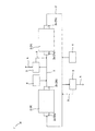
第二の実施形態にかかる石炭ガス化スラグ発泡体の製造システムを図3に示す。この石炭ガス化スラグ発泡体の製造システム1’は、石炭ガス化スラグを1000℃以下の温度で焼成する直列に並べられた複数台の焼成装置2と、焼成装置2の出口2bから排出される焼成済み石炭ガス化スラグを次段の焼成装置2の入口2aに搬送して投入する搬送手段3と、焼成済み石炭ガス化スラグを次段の焼成装置2に再投入する前に冷却する冷却手段4とを少なくとも備えるものである。また、第二の実施形態にかかる石炭ガス化スラグ発泡体の製造システム1は、最後段の焼成装置2Yの出口2Ybから排出される焼成済み石炭ガス化スラグを最前段の焼成装置2Xの入口2Xaに搬送して投入する搬送手段3’をさらに備えている。
(Second embodiment)
The production system of the coal gasification slag foam concerning 2nd embodiment is shown in FIG. This coal gasification slag
さらに、本実施形態では、搬送手段3に、焼成装置2Xから排出される焼成済み石炭ガス化スラグの比重を選別する比重選別装置5が備えられ、焼成済み石炭ガス化スラグのうち比重の基準値を満たすものを完成品として搬送手段3から取り除くと共に、焼成済み石炭ガス化スラグのうち比重の基準値を満たさないものを搬送手段3に戻し、搬送して焼成装置2Yに投入するようにしている。そして、焼成装置2Yから排出される焼成済み石炭ガス化スラグの比重を選別する比重選別装置5がさらに備えられ、焼成済み石炭ガス化スラグのうち比重の基準値を満たすものを完成品として搬送手段3’から取り除くと共に、焼成済み石炭ガス化スラグのうち比重の基準値を満たさないものを搬送手段3’に戻し、搬送して焼成装置2Xに投入するようにしている。
Furthermore, in this embodiment, the conveying
即ち、第一の実施形態の石炭ガス化スラグ発泡体の製造システム1と第二の実施形態の石炭ガス化スラグ発泡体の製造システム1’との違いは、焼成装置2を複数台備えて、複数台の焼成装置で順次焼成処理を行う点にある。
That is, the difference between the coal gasified slag
ここで、本実施形態では、焼成装置2を2台としているが、3台以上備えるようにしてもよい。
Here, in the present embodiment, two
また、本実施形態では、搬送手段3’を備えて、焼成装置2Yの出口2Ybから排出される焼成済み石炭ガス化スラグを焼成装置2Xに再投入することにより、3回以上の焼成処理を可能としているが、焼成装置2の台数以上に焼成処理を行わない場合には、本実施形態のように、搬送手段3’を備えて、焼成装置2Yの出口2Ybから排出される焼成済み石炭ガス化スラグを焼成装置2Xに再投入する形態とする必要はない。即ち、本実施形態において、焼成回数を2回とすれば良い場合には、搬送手段3’を備えて、焼成装置2Yの出口2Ybから排出される焼成済み石炭ガス化スラグを焼成装置2Xに再投入する形態とする必要はない。
Moreover, in this embodiment, it is possible to perform the calcination process three times or more by providing the conveying means 3 ′ and re-injecting the calcined coal gasification slag discharged from the outlet 2Yb of the
また、第一の実施形態と同様、焼成回数を何回程度とすればよいかが予めわかっている場合には、比重選別装置5を備えることなく、所定の回数の焼成を行うようにしてもよい。 Similarly to the first embodiment, when it is known in advance how many times the firing should be performed, the firing may be performed a predetermined number of times without providing the specific gravity sorting device 5. .
上述の形態は本発明の好適な形態の一例ではあるが、これに限定されるものではなく、本発明の要旨を逸脱しない範囲において種々変形実施可能である。 The above-described embodiment is an example of a preferred embodiment of the present invention, but is not limited to this, and various modifications can be made without departing from the scope of the present invention.
以下に本発明の実施例を説明するが、本発明はこれら実施例に限られるものではない。 Examples of the present invention will be described below, but the present invention is not limited to these examples.
(実施例1)
焼成済み石炭ガス化スラグを再焼成することによる効果について検討した。
Example 1
The effect of refired burned coal gasification slag was investigated.
本実施例において使用した石炭ガス化スラグの組成は、主要成分であるSiO2とAl2O3がそれぞれ60重量%と20重量%であり、その他の成分が20重量%(CaOが4重量%、Fe2O3が11重量%)含まれていた。 The composition of the coal gasification slag used in this example is 60% by weight and 20% by weight of the main components SiO 2 and Al 2 O 3 , respectively, and the other components are 20% by weight (CaO is 4% by weight). , Fe 2 O 3 was 11 wt%).
この石炭ガス化スラグを焼成装置に投入して焼成し、焼成温度に対するかさ比重を調べ、焼成温度に対する石炭ガス化スラグの発泡性について検討した。焼成装置には、外熱式ロータリーキルン(高砂工業製TRK−300G)を用いた。また、焼成温度の制御は、ロータリーキルンの出口温度を910℃で一定に保ち、入口温度を変化させることにより行った。加熱滞留時間(石炭ガス化スラグのロータリーキルンのシェル内滞留時間)は6分間とした。 This coal gasification slag was put into a firing apparatus and fired, the bulk specific gravity with respect to the firing temperature was examined, and the foamability of the coal gasification slag with respect to the firing temperature was examined. An external heating type rotary kiln (TRK-300G manufactured by Takasago Industry) was used as the baking apparatus. The firing temperature was controlled by keeping the outlet temperature of the rotary kiln constant at 910 ° C. and changing the inlet temperature. The heating residence time (the residence time in the shell of the rotary kiln of the coal gasification slag) was 6 minutes.
さらに、上記と同様の条件で一度焼成した石炭ガス化スラグを室温まで冷却(室温で放置して徐冷)した後、再度焼成装置に投入して再焼成し、焼成温度に対するかさ比重を調べた。再焼成の際の加熱滞留時間も6分間とした。 Furthermore, after the coal gasification slag fired once under the same conditions as above was cooled to room temperature (slowly cooled by leaving it at room temperature), it was again put into a firing device and refired, and the bulk specific gravity with respect to the firing temperature was examined. . The heating residence time during refiring was also 6 minutes.
「かさ比重」は、円錐型のガラス製油量計(内容積約190cc)にすり切りいっぱいの石炭ガス化スラグ発泡体をつめ、容積と重量から算出して求めた。尚、かさ比重の測定は常温で行った。 The “bulk specific gravity” was determined by packing a coal gasified slag foam filled with a conical glass oil meter (internal volume of about 190 cc) and calculating from the volume and weight. The bulk specific gravity was measured at room temperature.
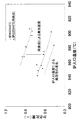
実験結果を図1に示す。焼成回数を1回とした場合の結果を△で示し、焼成回数を2回としたものを▲で示した。この結果から、いずれの焼成温度条件においても、焼成回数を2回とすることで、かさ比重が低減することが確認された。特に、焼成温度を910℃とした場合には、超軽量発泡体の目標かさ比重である0.6以下のかさ比重を有する石炭ガス化スラグ発泡体が得られた。この結果から、石炭ガス化スラグを1000℃以下の温度で2回焼成すると共に、1回目の焼成の後に室温まで冷却することが、石炭ガス化スラグの発泡促進に対して効果的であることが明らかとなった。即ち、石炭ガス化スラグを1000℃以下の温度で焼成する工程を、石炭ガス化スラグを冷却する工程を挟みながら複数回行うことで、石炭ガス化スラグの発泡性を促進できることがこの実験から明らかとなった。 The experimental results are shown in FIG. The result when the number of firings was 1 was indicated by Δ, and the result when the number of firings was 2 was indicated by ▲. From these results, it was confirmed that the bulk specific gravity was reduced by setting the number of times of firing to 2 under any firing temperature condition. In particular, when the firing temperature was 910 ° C., a coal gasified slag foam having a bulk specific gravity of 0.6 or less, which is the target bulk specific gravity of the ultralight foam, was obtained. From this result, it is effective to promote the foaming of the coal gasification slag that the coal gasification slag is fired twice at a temperature of 1000 ° C. or less and cooled to room temperature after the first firing. It became clear. That is, it is clear from this experiment that the foaming property of coal gasification slag can be promoted by performing the process of firing coal gasification slag at a temperature of 1000 ° C. or less multiple times while sandwiching the process of cooling coal gasification slag. It became.
1,1’ 石炭ガス化スラグ発泡体の製造システム
2 焼成装置
3,3’ 搬送手段
4 冷却手段
5 比重選別装置
1, 1 'Coal gasification slag
Claims (3)
前記搬送手段には、前記焼成済み石炭ガス化スラグの比重を選別し、前記焼成済み石炭ガス化スラグのうち比重の基準値を満たすものを完成品として前記搬送手段から取り除くと共に、前記焼成済み石炭ガス化スラグのうち比重の基準値を満たさないものを前記搬送手段に戻す比重選別装置が備えられていることを特徴とする石炭ガス化スラグ発泡体の製造システム。 A calcining apparatus for calcining coal gasification slag at a temperature of 800 ° C. or more and 1000 ° C. or less, and conveying means for conveying the calcined coal gasification slag discharged from the outlet of the calcining apparatus to the inlet of the calcining apparatus and re-injecting it. And at least cooling means for cooling the calcined coal gasification slag to 600 ° C. or lower before recharging the calcined apparatus ,
The conveying means selects the specific gravity of the calcined coal gasification slag, and removes the calcined coal gasification slag that satisfies the specific gravity standard value from the conveying means as a finished product, and the calcined coal A system for producing a coal gasified slag foam , comprising a specific gravity sorting device for returning a gasification slag that does not satisfy a specific value of specific gravity to the transport means .
前記搬送手段には、前記焼成済み石炭ガス化スラグの比重を選別し、前記焼成済み石炭ガス化スラグのうち比重の基準値を満たすものを完成品として前記搬送手段から取り除くと共に、前記焼成済み石炭ガス化スラグのうち比重の基準値を満たさないものを前記搬送手段に戻す比重選別装置が備えられていることを特徴とする石炭ガス化スラグ発泡体の製造システム。 A plurality of calcination devices arranged in series for calcination of coal gasification slag at a temperature of 800 ° C. or higher and 1000 ° C. or lower, and the calcined coal gasification slag discharged from the outlet of the calciner at the next stage Transporting means for transporting and feeding to the inlet, and at least cooling means for cooling the calcined coal gasification slag to 600 ° C. or less before recharging to the next-stage firing device ,
The conveying means selects the specific gravity of the calcined coal gasification slag, and removes the calcined coal gasification slag that satisfies the specific gravity standard value from the conveying means as a finished product, and the calcined coal A system for producing a coal gasified slag foam , comprising a specific gravity sorting device for returning a gasification slag that does not satisfy a specific value of specific gravity to the transport means .
Priority Applications (1)
| Application Number | Priority Date | Filing Date | Title |
|---|---|---|---|
| JP2008118631A JP5006830B2 (en) | 2008-04-30 | 2008-04-30 | Coal gasification slag foam production system |
Applications Claiming Priority (1)
| Application Number | Priority Date | Filing Date | Title |
|---|---|---|---|
| JP2008118631A JP5006830B2 (en) | 2008-04-30 | 2008-04-30 | Coal gasification slag foam production system |
Related Child Applications (1)
| Application Number | Title | Priority Date | Filing Date |
|---|---|---|---|
| JP2012097307A Division JP5758343B2 (en) | 2012-04-23 | 2012-04-23 | Method and system for producing coal gasified slag foam |
Publications (2)
| Publication Number | Publication Date |
|---|---|
| JP2009269760A JP2009269760A (en) | 2009-11-19 |
| JP5006830B2 true JP5006830B2 (en) | 2012-08-22 |
Family
ID=41436670
Family Applications (1)
| Application Number | Title | Priority Date | Filing Date |
|---|---|---|---|
| JP2008118631A Expired - Fee Related JP5006830B2 (en) | 2008-04-30 | 2008-04-30 | Coal gasification slag foam production system |
Country Status (1)
| Country | Link |
|---|---|
| JP (1) | JP5006830B2 (en) |
Families Citing this family (2)
| Publication number | Priority date | Publication date | Assignee | Title |
|---|---|---|---|---|
| US8992794B2 (en) * | 2011-06-24 | 2015-03-31 | Basf Corporation | Process for synthesis of a layered oxide cathode composition |
| JP5758343B2 (en) * | 2012-04-23 | 2015-08-05 | 一般財団法人電力中央研究所 | Method and system for producing coal gasified slag foam |
Family Cites Families (6)
| Publication number | Priority date | Publication date | Assignee | Title |
|---|---|---|---|---|
| JPS61197479A (en) * | 1985-02-22 | 1986-09-01 | 宇部興産株式会社 | Inorganic foam and manufacture |
| JPS61251551A (en) * | 1985-04-30 | 1986-11-08 | 宇部興産株式会社 | Inorganic foam and manufacture |
| JPH0678182B2 (en) * | 1989-02-03 | 1994-10-05 | 宇部興産株式会社 | Method for producing inorganic foam |
| JP3633266B2 (en) * | 1998-03-03 | 2005-03-30 | 宇部興産株式会社 | Method for producing inorganic foam |
| JP4601138B2 (en) * | 2000-08-17 | 2010-12-22 | 財団法人電力中央研究所 | Manufacturing method of artificial lightweight aggregate |
| JP2008088331A (en) * | 2006-10-03 | 2008-04-17 | Central Res Inst Of Electric Power Ind | Prediction method and program for optimum foaming temperature and gasification characteristics of coal gasification slag |
-
2008
- 2008-04-30 JP JP2008118631A patent/JP5006830B2/en not_active Expired - Fee Related
Also Published As
| Publication number | Publication date |
|---|---|
| JP2009269760A (en) | 2009-11-19 |
Similar Documents
| Publication | Publication Date | Title |
|---|---|---|
| CN102015568B (en) | CO2 gas recovery method and recovery equipment in cement manufacturing equipment | |
| JP5006830B2 (en) | Coal gasification slag foam production system | |
| JP6534423B2 (en) | Fly ash cooling system | |
| CN105579415B (en) | Operation method of cement manufacturing equipment | |
| CN102617118A (en) | Method for preparing high-purity tabular corundum with low energy consumption | |
| JP5758343B2 (en) | Method and system for producing coal gasified slag foam | |
| JP2006528123A (en) | Methods and equipment for cement production | |
| CN105154662B (en) | Rare earth miberal powder Roasting Decomposition system and its technique | |
| RU2009145277A (en) | Self-fluxing pellets for blast furnaces and the method of their manufacture | |
| JP5534118B2 (en) | Raw material charging method to blast furnace | |
| EP1995222A1 (en) | Method and system for preheating glass batch or ingredient(s) | |
| CN108046630A (en) | It is a kind of using copper ashes magnetic separation slag and coal ash for manufacturing for the method for sintering-expanded haydite | |
| CN1048758C (en) | Method for producing sinter | |
| WO2020189109A1 (en) | Fly ash modification method | |
| WO2013099186A1 (en) | Bulk-material cooling device and bulk-material cooling method | |
| US2080981A (en) | Process and apparatus for the production of lime and carbon dioxide | |
| CN101774553A (en) | Method for calcining raw materials in furnace in yellow phosphorus production | |
| CN204574779U (en) | A kind of amorphous powder core sintering processes system | |
| JP6050987B2 (en) | Carbide manufacturing method and carbide manufacturing system | |
| JP6722839B1 (en) | Method of modifying fly ash | |
| JP2013053057A (en) | Method for manufacturing cement | |
| EP2738149B1 (en) | Method of manufacturing porous construction items | |
| JP2010037164A (en) | Method for producing high strength and high sphericity glassy fine hollow sphere | |
| EP1914200B1 (en) | Calcined tincal production method by calcination autogenic grinding and separation (CASG) method in a single step | |
| JP5842738B2 (en) | Blast furnace operation method |
Legal Events
| Date | Code | Title | Description |
|---|---|---|---|
| A621 | Written request for application examination |
Free format text: JAPANESE INTERMEDIATE CODE: A621 Effective date: 20110114 |
|
| A977 | Report on retrieval |
Free format text: JAPANESE INTERMEDIATE CODE: A971007 Effective date: 20120208 |
|
| A131 | Notification of reasons for refusal |
Free format text: JAPANESE INTERMEDIATE CODE: A131 Effective date: 20120221 |
|
| A521 | Written amendment |
Free format text: JAPANESE INTERMEDIATE CODE: A523 Effective date: 20120423 |
|
| TRDD | Decision of grant or rejection written | ||
| A01 | Written decision to grant a patent or to grant a registration (utility model) |
Free format text: JAPANESE INTERMEDIATE CODE: A01 Effective date: 20120522 |
|
| A01 | Written decision to grant a patent or to grant a registration (utility model) |
Free format text: JAPANESE INTERMEDIATE CODE: A01 |
|
| A61 | First payment of annual fees (during grant procedure) |
Free format text: JAPANESE INTERMEDIATE CODE: A61 Effective date: 20120525 |
|
| FPAY | Renewal fee payment (event date is renewal date of database) |
Free format text: PAYMENT UNTIL: 20150601 Year of fee payment: 3 |
|
| R150 | Certificate of patent or registration of utility model |
Ref document number: 5006830 Country of ref document: JP Free format text: JAPANESE INTERMEDIATE CODE: R150 Free format text: JAPANESE INTERMEDIATE CODE: R150 |
|
| R250 | Receipt of annual fees |
Free format text: JAPANESE INTERMEDIATE CODE: R250 |
|
| R250 | Receipt of annual fees |
Free format text: JAPANESE INTERMEDIATE CODE: R250 |
|
| R250 | Receipt of annual fees |
Free format text: JAPANESE INTERMEDIATE CODE: R250 |
|
| R250 | Receipt of annual fees |
Free format text: JAPANESE INTERMEDIATE CODE: R250 |
|
| R250 | Receipt of annual fees |
Free format text: JAPANESE INTERMEDIATE CODE: R250 |
|
| R250 | Receipt of annual fees |
Free format text: JAPANESE INTERMEDIATE CODE: R250 |
|
| LAPS | Cancellation because of no payment of annual fees |