JP5018704B2 - 脱穀装置 - Google Patents
脱穀装置 Download PDFInfo
- Publication number
- JP5018704B2 JP5018704B2 JP2008221806A JP2008221806A JP5018704B2 JP 5018704 B2 JP5018704 B2 JP 5018704B2 JP 2008221806 A JP2008221806 A JP 2008221806A JP 2008221806 A JP2008221806 A JP 2008221806A JP 5018704 B2 JP5018704 B2 JP 5018704B2
- Authority
- JP
- Japan
- Prior art keywords
- sorting
- flow fan
- cross
- shelf
- dust
- Prior art date
- Legal status (The legal status is an assumption and is not a legal conclusion. Google has not performed a legal analysis and makes no representation as to the accuracy of the status listed.)
- Expired - Fee Related
Links
- 238000012545 processing Methods 0.000 claims description 110
- 239000000428 dust Substances 0.000 claims description 62
- 238000012546 transfer Methods 0.000 claims description 23
- 238000000034 method Methods 0.000 claims description 4
- 230000008569 process Effects 0.000 claims description 3
- 241000251169 Alopias vulpinus Species 0.000 claims description 2
- 230000005540 biological transmission Effects 0.000 description 46
- 238000009792 diffusion process Methods 0.000 description 36
- 210000000515 tooth Anatomy 0.000 description 19
- 239000000463 material Substances 0.000 description 18
- 230000007246 mechanism Effects 0.000 description 15
- 235000013339 cereals Nutrition 0.000 description 13
- 238000001514 detection method Methods 0.000 description 13
- 230000008859 change Effects 0.000 description 10
- 230000009471 action Effects 0.000 description 6
- 238000005192 partition Methods 0.000 description 5
- 238000012423 maintenance Methods 0.000 description 4
- 238000013459 approach Methods 0.000 description 3
- 230000008901 benefit Effects 0.000 description 3
- 239000002245 particle Substances 0.000 description 3
- 230000009467 reduction Effects 0.000 description 3
- 238000004140 cleaning Methods 0.000 description 2
- 230000008878 coupling Effects 0.000 description 2
- 238000010168 coupling process Methods 0.000 description 2
- 238000005859 coupling reaction Methods 0.000 description 2
- 238000010586 diagram Methods 0.000 description 2
- 230000000694 effects Effects 0.000 description 2
- 230000002706 hydrostatic effect Effects 0.000 description 2
- 238000003780 insertion Methods 0.000 description 2
- 230000037431 insertion Effects 0.000 description 2
- 230000010355 oscillation Effects 0.000 description 2
- 230000004044 response Effects 0.000 description 2
- 238000000926 separation method Methods 0.000 description 2
- 240000007594 Oryza sativa Species 0.000 description 1
- 235000007164 Oryza sativa Nutrition 0.000 description 1
- 238000010521 absorption reaction Methods 0.000 description 1
- 230000002411 adverse Effects 0.000 description 1
- 230000015572 biosynthetic process Effects 0.000 description 1
- 239000003638 chemical reducing agent Substances 0.000 description 1
- 238000011109 contamination Methods 0.000 description 1
- 230000003247 decreasing effect Effects 0.000 description 1
- 238000003795 desorption Methods 0.000 description 1
- 230000014509 gene expression Effects 0.000 description 1
- 230000009191 jumping Effects 0.000 description 1
- 230000001737 promoting effect Effects 0.000 description 1
- 235000009566 rice Nutrition 0.000 description 1
- 238000000638 solvent extraction Methods 0.000 description 1
- 230000001360 synchronised effect Effects 0.000 description 1
- 239000002699 waste material Substances 0.000 description 1
Images







Landscapes
- Threshing Machine Elements (AREA)
Description
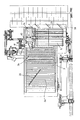
即ち、請求項1記載の発明は、内部に扱胴(14)を軸架した扱室(15)の前側に穀稈供給口(13)を開口し、該穀稈供給口(13)から連続して開口させた扱口(19)の外側に沿わせて挟持杆(16)とフィードチェン(17)とからなる挟持搬送装置(18)を設け、揺動選別棚(3)を備えた選別室(2)を扱室(15)の下方から後方にわたって設け、該揺動選別棚(3)の下方の位置に、選別方向の上手側から圧風唐箕(20)と一番移送螺旋(21)と二番移送螺旋(22)を順に配置し、前記揺動選別棚(3)の始端部分を扱室(15)の下方に臨ませて配置し、該揺動選別棚(3)の終端部の上方には横断流ファン(5)を横向きに軸架し、該横断流ファン(5)の吸塵口(6)を下方に向けると共に排塵口(33)を機外に向けて設け、前記選別室(2)内に形成する選別風路(24)の基部を圧風唐箕(20)に連通させ、該選別風路(24)を揺動選別棚(3)内を通過させて後部の横断流ファン(5)側に向けて設け、平面視において前記横断流ファン(5)の左側の部位に片側吸引式ファン(4)を配置し、前記揺動選別棚(3)よりも上側の位置に、平面視において前記片側吸引式ファン(4)と脱穀装置(1)の正面視左側の側板(9)との間に配置されると共に該側板(9)の近傍にのみ設けられて前記二番移送螺旋(22)に連動して駆動される処理胴(10)を配置し、該処理胴(10)における正面視右側の部位を揺動選別棚(3)の上方において開放し、該処理胴(10)に取り付けた複数のツース(40)によって処理物を横断流ファン(5)の前方側の揺動選別棚(3)上に跳ね出しながら送る構成とした脱穀装置とした。
請求項2記載の発明は、前記処理胴(10)における正面視左側の部位にツース(40)を設けない部分(11)を形成し、このツース(40)を設けない部分(11)を揺動選別棚(3)の正面視左側の側壁(41)の上部に接近した部位に配置し、該側壁(41)と処理胴(10)下部のツース(40)とが側面視で重合する構成とした請求項1記載の脱穀装置とした。
まず、本件出願の明細書中に記載した左側、及び右側の表現は、脱穀装置1の穀稈供給口13側(図1や図4に示す正面視)から見た状態を基準にして左右を判断し、記載している。
そして、横断流ファン5は、図1、及び図2に示すように、揺動選別棚3の終端部分でストローラック3cの上方に横向きに軸架して設け、吸塵口6を下方に向け、排塵口33を機外に向けて構成している。そして、片側吸引式ファン4は、図面から解るように、上記横断流ファン5の左横側で排塵処理室8に近い側に配置して、横断流ファン5との間の仕切壁34を設けて区画し、別軸に軸受けさせた構成としている。
なお、拡散処理胴10は、図11に示すように、ツース歯40に代えて螺旋処理歯42を取り付けた構成にしても良い。この螺旋処理歯42は、揺動選別棚3上の処理物が一定層以上の高さに達すると、その高い部分に連続的に作用して確実に横断流ファン5の前方側の棚3上に向けて斜めに跳ね出しながら送ることができる特徴がある。
まず、エンジン60は、図13に示すように、出力する回転動力を二手に分岐して、一方を静油圧式無段変速装置61を経由して走行ミッション装置62に入力し、他方を脱穀装置1に入力する構成としている。そして、脱穀装置1は、唐箕軸63に入力された動力を、扱胴14、及び二番処理胴29側と、揺動選別装置3の揺動機構23とフィードチェン17側と、更に、圧風唐箕20は勿論のこと、一番、二番の移送螺旋21,22側に分岐して伝動する構成としている。
このように、横断流ファン5と、拡散処理胴10、及び片側吸引式ファン4とは、前者が右側の機体側板9側から入力して駆動され、後者が左側の機体側板9側から入力して駆動される伝動の配置構成としている。
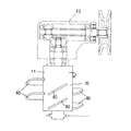
まず、横断流ファン5と片側吸引式ファン4とは、図15に示すように、機体内部のケーシング38に摺動自由に支持している仕切壁34に、それぞれベヤリング75、75を介して軸受け支持した2つの支持軸76,77を設け、一方の短い支持軸76に片側吸引式ファン4を軸着し、他方の長い支持軸77に横断流ファン5を軸着して構成している。そして、短い支持軸76は、図16で解るように、ケーシング38側の支持板35(外側)に固定する軸受装置78と伝動スプロケット36とを着脱自由に軸着するカップリング部79を形成した構成としている。そして、長い支持軸77は、端部(外側)に軸受装置80を支持して設け、この軸受装置80に取付側板81を一体に支持して構成している。そして、該軸受装置80は、その外側に一対の噛合したカウンターギヤ82,83と、変速プーリ70とを一体に支持した構成としている。
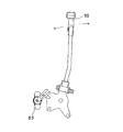
まず、制御モータ91は、図19、及び図20に示すように、ピニオンギヤ92をラックギヤ93に噛合させて設け、連動アーム94を介して制御ロット95を押し引き操作して変速プーリ65のベルト伝動径を拡縮調節する構成としている。96はテンションプーリを示している。
つぎに、二番処理室28に二番検出センサ107を設けて室内の処理量の増・減を検出して変速制御を行う構成を説明する。
2 選別室
3 揺動選別棚
3a 移送棚
3b チャフシーブ
4 片側吸引式ファン
5 横断流ファン
6 吸塵口
8 排塵処理室
9 機体側板(側板)
10 拡散処理胴(処理胴)
11 部分(ツースを設けない部分)
13 穀稈供給口
14 扱胴
15 扱室
16 挟持杆
17 フィードチェン
18 挟持搬送装置
19 扱口
20 圧風唐箕
21 一番移送螺旋
22 二番移送螺旋
23 揺動機構
24 選別風路
33 排塵口
40 ツース歯(ツース)
41 側壁
43 拡散処理胴駆動ケース
Claims (2)
- 内部に扱胴(14)を軸架した扱室(15)の前側に穀稈供給口(13)を開口し、該穀稈供給口(13)から連続して開口させた扱口(19)の外側に沿わせて挟持杆(16)とフィードチェン(17)とからなる挟持搬送装置(18)を設け、揺動選別棚(3)を備えた選別室(2)を扱室(15)の下方から後方にわたって設け、該揺動選別棚(3)の下方の位置に、選別方向の上手側から圧風唐箕(20)と一番移送螺旋(21)と二番移送螺旋(22)を順に配置し、前記揺動選別棚(3)の始端部分を扱室(15)の下方に臨ませて配置し、該揺動選別棚(3)の終端部の上方には横断流ファン(5)を横向きに軸架し、該横断流ファン(5)の吸塵口(6)を下方に向けると共に排塵口(33)を機外に向けて設け、前記選別室(2)内に形成する選別風路(24)の基部を圧風唐箕(20)に連通させ、該選別風路(24)を揺動選別棚(3)内を通過させて後部の横断流ファン(5)側に向けて設け、平面視において前記横断流ファン(5)の左側の部位に片側吸引式ファン(4)を配置し、前記揺動選別棚(3)よりも上側の位置に、平面視において前記片側吸引式ファン(4)と脱穀装置(1)の正面視左側の側板(9)との間に配置されると共に該側板(9)の近傍にのみ設けられて前記二番移送螺旋(22)に連動して駆動される処理胴(10)を配置し、該処理胴(10)における正面視右側の部位を揺動選別棚(3)の上方において開放し、該処理胴(10)に取り付けた複数のツース(40)によって処理物を横断流ファン(5)の前方側の揺動選別棚(3)上に跳ね出しながら送る構成とした脱穀装置。
- 前記処理胴(10)における正面視左側の部位にツース(40)を設けない部分(11)を形成し、このツース(40)を設けない部分(11)を揺動選別棚(3)の正面視左側の側壁(41)の上部に接近した部位に配置し、該側壁(41)と処理胴(10)下部のツース(40)とが側面視で重合する構成とした請求項1記載の脱穀装置。
Priority Applications (1)
| Application Number | Priority Date | Filing Date | Title |
|---|---|---|---|
| JP2008221806A JP5018704B2 (ja) | 2008-08-29 | 2008-08-29 | 脱穀装置 |
Applications Claiming Priority (1)
| Application Number | Priority Date | Filing Date | Title |
|---|---|---|---|
| JP2008221806A JP5018704B2 (ja) | 2008-08-29 | 2008-08-29 | 脱穀装置 |
Related Parent Applications (1)
| Application Number | Title | Priority Date | Filing Date |
|---|---|---|---|
| JP2005314743A Division JP2007117008A (ja) | 2005-10-28 | 2005-10-28 | 脱穀装置 |
Related Child Applications (1)
| Application Number | Title | Priority Date | Filing Date |
|---|---|---|---|
| JP2011017328A Division JP5533702B2 (ja) | 2011-01-29 | 2011-01-29 | 脱穀装置 |
Publications (2)
| Publication Number | Publication Date |
|---|---|
| JP2008307060A JP2008307060A (ja) | 2008-12-25 |
| JP5018704B2 true JP5018704B2 (ja) | 2012-09-05 |
Family
ID=40235232
Family Applications (1)
| Application Number | Title | Priority Date | Filing Date |
|---|---|---|---|
| JP2008221806A Expired - Fee Related JP5018704B2 (ja) | 2008-08-29 | 2008-08-29 | 脱穀装置 |
Country Status (1)
| Country | Link |
|---|---|
| JP (1) | JP5018704B2 (ja) |
Families Citing this family (1)
| Publication number | Priority date | Publication date | Assignee | Title |
|---|---|---|---|---|
| JP5361351B2 (ja) | 2007-12-07 | 2013-12-04 | キヤノン株式会社 | シート処理装置及び画像形成装置及び画像形成システム |
Family Cites Families (6)
| Publication number | Priority date | Publication date | Assignee | Title |
|---|---|---|---|---|
| JPS5715139U (ja) * | 1980-06-27 | 1982-01-26 | ||
| JPS6121962Y2 (ja) * | 1980-08-20 | 1986-07-01 | ||
| JPS60162431U (ja) * | 1984-04-06 | 1985-10-29 | ヤンマー農機株式会社 | 脱穀機における選別排塵装置 |
| JPH07284323A (ja) * | 1994-04-18 | 1995-10-31 | Iseki & Co Ltd | コンバインの脱穀装置 |
| JP3814198B2 (ja) * | 2001-05-23 | 2006-08-23 | ヤンマー農機株式会社 | コンバイン |
| JP3963746B2 (ja) * | 2002-03-19 | 2007-08-22 | セイレイ工業株式会社 | 搭載用脱穀機の揺動選別装置 |
-
2008
- 2008-08-29 JP JP2008221806A patent/JP5018704B2/ja not_active Expired - Fee Related
Also Published As
| Publication number | Publication date |
|---|---|
| JP2008307060A (ja) | 2008-12-25 |
Similar Documents
| Publication | Publication Date | Title |
|---|---|---|
| JP5018704B2 (ja) | 脱穀装置 | |
| JP5533702B2 (ja) | 脱穀装置 | |
| JP2011103894A5 (ja) | ||
| JP2007117008A5 (ja) | ||
| JP2007117008A (ja) | 脱穀装置 | |
| JP2009247287A (ja) | コンバイン | |
| JP2005261280A (ja) | コンバイン | |
| JP2011072288A (ja) | コンバイン | |
| JP5998678B2 (ja) | コンバイン | |
| JP4315846B2 (ja) | コンバイン | |
| JP2006067814A (ja) | 脱穀機のささり粒回収装置 | |
| JP5849916B2 (ja) | コンバイン | |
| JP2009148290A (ja) | コンバイン | |
| JP4526086B2 (ja) | コンバイン | |
| JP3704798B2 (ja) | 脱穀機 | |
| JP2009055853A (ja) | 脱穀装置 | |
| JP5838619B2 (ja) | 刈取装置 | |
| JP6015526B2 (ja) | コンバイン | |
| JP2008283919A (ja) | コンバイン | |
| JP2015119675A (ja) | コンバイン | |
| JP2545788Y2 (ja) | 脱穀機における二番還元装置 | |
| JP4400056B2 (ja) | コンバイン | |
| JP5218732B2 (ja) | 脱穀装置 | |
| JP4394986B2 (ja) | コンバイン | |
| JP5472826B2 (ja) | 脱穀装置 |
Legal Events
| Date | Code | Title | Description |
|---|---|---|---|
| A621 | Written request for application examination |
Free format text: JAPANESE INTERMEDIATE CODE: A621 Effective date: 20080926 |
|
| A977 | Report on retrieval |
Free format text: JAPANESE INTERMEDIATE CODE: A971007 Effective date: 20110428 |
|
| A131 | Notification of reasons for refusal |
Free format text: JAPANESE INTERMEDIATE CODE: A131 Effective date: 20110517 |
|
| A521 | Request for written amendment filed |
Free format text: JAPANESE INTERMEDIATE CODE: A523 Effective date: 20110718 |
|
| A131 | Notification of reasons for refusal |
Free format text: JAPANESE INTERMEDIATE CODE: A131 Effective date: 20120214 |
|
| A521 | Request for written amendment filed |
Free format text: JAPANESE INTERMEDIATE CODE: A523 Effective date: 20120413 |
|
| TRDD | Decision of grant or rejection written | ||
| A01 | Written decision to grant a patent or to grant a registration (utility model) |
Free format text: JAPANESE INTERMEDIATE CODE: A01 Effective date: 20120515 |
|
| A01 | Written decision to grant a patent or to grant a registration (utility model) |
Free format text: JAPANESE INTERMEDIATE CODE: A01 |
|
| A61 | First payment of annual fees (during grant procedure) |
Free format text: JAPANESE INTERMEDIATE CODE: A61 Effective date: 20120528 |
|
| R150 | Certificate of patent or registration of utility model |
Ref document number: 5018704 Country of ref document: JP Free format text: JAPANESE INTERMEDIATE CODE: R150 Free format text: JAPANESE INTERMEDIATE CODE: R150 |
|
| FPAY | Renewal fee payment (event date is renewal date of database) |
Free format text: PAYMENT UNTIL: 20150622 Year of fee payment: 3 |
|
| LAPS | Cancellation because of no payment of annual fees |