JP5055331B2 - Image display device and image display method - Google Patents
Image display device and image display method Download PDFInfo
- Publication number
- JP5055331B2 JP5055331B2 JP2009202400A JP2009202400A JP5055331B2 JP 5055331 B2 JP5055331 B2 JP 5055331B2 JP 2009202400 A JP2009202400 A JP 2009202400A JP 2009202400 A JP2009202400 A JP 2009202400A JP 5055331 B2 JP5055331 B2 JP 5055331B2
- Authority
- JP
- Japan
- Prior art keywords
- point
- image
- screen
- coordinates
- image display
- Prior art date
- Legal status (The legal status is an assumption and is not a legal conclusion. Google has not performed a legal analysis and makes no representation as to the accuracy of the status listed.)
- Expired - Fee Related
Links
Images



Landscapes
- User Interface Of Digital Computer (AREA)
Description
本発明は、画像表示装置および画像表示方法に関するものである。 The present invention relates to an image display device and an image display method.
従来にあっては、地図や商品の画像を表示するアプリケーションにおいて、画像内の箇所や画像を見る角度を指定するのに、マウスドラッグやボタン操作が行われる。例えば、特許文献1の発明では、予め回転軸を定義し、スライダを動かすことによって、画像の回転を可能にしている。
Conventionally, in an application that displays an image of a map or a product, a mouse drag or a button operation is performed to designate a location in the image or an angle for viewing the image. For example, in the invention of
しかし、従来にあっては、画像の移動と回転を同時に行えず、所望の箇所を所望の角度で見るには、画像を移動させる操作と画像を回転させる操作を分けて行う必要があった。 However, conventionally, the image cannot be moved and rotated at the same time, and in order to view a desired portion at a desired angle, the operation for moving the image and the operation for rotating the image have to be performed separately.
本発明は上記に鑑みなされたものであり、その目的とするところは、画像を移動させる操作と画像を回転させる操作を分けて行うことなく画像を移動および回転させることが可能な画像表示装置および画像表示方法を提供することにある。 The present invention has been made in view of the above, and an object thereof is to provide an image display device capable of moving and rotating an image without separately performing an operation of moving the image and an operation of rotating the image, and It is to provide an image display method.
上記の課題を解決するために、本発明の画像表示装置は、画像が表示される画面内で指定された2点の当該画面での座標を取得する座標取得部と、前記第1の点の座標を用いて、前記画面で予め定められた点と前記第1の点とを通過する直線と当該画面における座標の基準軸とでなす角度を算出し、前記予め定められた点と前記第1の点との間の距離を算出する角度距離算出部と、前記第2の点の座標を用いて、前記予め定められた点と前記第2の点とを通過する直線と前記基準軸とでなす角度を算出し、前記予め定められた点と前記第2の点との間の距離を算出する角度距離算出部と、前記画像を前記2つの距離の差分に応じた距離だけ平行移動させ、前記画像を前記2つの角度の差分に応じた角度だけ回転させる画像表示制御部とを備えることを特徴とする。 In order to solve the above-described problem, an image display device according to the present invention includes a coordinate acquisition unit that acquires the coordinates of two points designated in a screen on which an image is displayed, and the first point. An angle formed by a straight line passing through a predetermined point on the screen and the first point and a reference axis of the coordinate on the screen is calculated using the coordinates, and the predetermined point and the first point are calculated. An angle distance calculation unit for calculating a distance between the second point, a straight line passing through the predetermined point and the second point using the coordinates of the second point, and the reference axis An angle formed by calculating an angle, an angle distance calculating unit calculating a distance between the predetermined point and the second point, and translating the image by a distance corresponding to a difference between the two distances; An image display control unit that rotates the image by an angle corresponding to a difference between the two angles. It is characterized in.
例えば、前記画像表示装置は、前記画面に表示されるポインタを動かすために用いられ且つ当該ポインタが前記画面に表示されているときに操作される操作部を備える入力装置ととともに使用されるものであり、前記座標取得部は、前記操作部への操作が開始されたときに前記ポインタが存在する前記第1の点の座標と前記操作部への操作が終了したときに前記ポインタが存在する前記第2の点の座標とを取得することを特徴とする。 For example, the image display device is used together with an input device that is used to move a pointer displayed on the screen and includes an operation unit that is operated when the pointer is displayed on the screen. And the coordinate acquisition unit includes the coordinates of the first point where the pointer exists when the operation to the operation unit is started and the pointer where the pointer exists when the operation to the operation unit ends. The coordinates of the second point are acquired.
本発明の画像表示方法は、画像が表示される画面内で指定された2点の当該画面での座標を取得するステップ、前記第1の点の座標を用いて、前記予め定められた点と前記第1の点とを通過する直線と当該画面における座標の基準軸とでなす角度を算出し、前記予め定められた点と前記第1の点との間の距離を算出するステップと、前記第2の点の座標を用いて、前記画面内の前記予め定められた点と前記第2の点とを通過する直線と前記基準軸とでなす角度を算出し、前記予め定められた点と前記第2の点との間の距離を算出するステップと、前記画像を前記2つの距離の差分に応じた距離だけ平行移動させ、前記画像を前記2つの角度の差分に応じた角度だけ回転させるステップとを含むことを特徴とする。 In the image display method of the present invention, the step of obtaining the coordinates of the two points designated in the screen on which the image is displayed, the predetermined point using the coordinates of the first point, Calculating an angle formed by a straight line passing through the first point and a reference axis of coordinates on the screen, and calculating a distance between the predetermined point and the first point; Using the coordinates of the second point, an angle formed between the predetermined point in the screen and the straight line passing through the second point and the reference axis is calculated, and the predetermined point is Calculating a distance between the second point, translating the image by a distance according to a difference between the two distances, and rotating the image by an angle according to the difference between the two angles; And a step.
本発明によれば、画像を移動させる操作と画像を回転させる操作を分けて行うことなく画像を移動および回転させることができる。よって、操作を分けることに伴う煩わしさを解消できる。 According to the present invention, it is possible to move and rotate an image without separately performing an operation for moving the image and an operation for rotating the image. Therefore, the troublesomeness associated with dividing the operation can be eliminated.
以下、本発明の実施の形態を図面を参照して説明する。 Hereinafter, embodiments of the present invention will be described with reference to the drawings.
図1は、本実施の形態に係る画像表示装置の構成を示すブロック図である。 FIG. 1 is a block diagram showing the configuration of the image display apparatus according to this embodiment.
画像表示装置は、入力装置1、中央処理制御装置2および記憶装置3を備える。
The image display device includes an
入力装置1は、図示しない記録媒体などから画像データを取得する画像データ取得部11と、図示しない表示装置の画面での座標を取得する座標取得部12とを備える。
The
座標取得部12は、図示しないマウスやトラックボールやタッチパッドなど、つまり、画面に表示されるポインタを動かすために用いられ且つポインタが画面に表示されているときに操作されるボタンなどの操作部を備える入力装置(マウスなど)に接続されたインタフェース部などから、操作部への操作が実行されたときにポインタが存在する点の画面での座標を取得する。
The
座標取得部12は、例えば、操作部への操作(例えば、マウスの左ボタンを押し続け、ポインタが移動したところで左ボタンを放す操作、つまりドラッグアンドドロップ)が開始されたときにポインタが存在する第1の点の画面での座標と、操作部への操作が終了したとき(いわゆるドロップしたとき)にポインタが存在する第2の点の画面での座標とを取得する。
For example, the
中央処理制御装置2は、第1の点の座標を用いて、画面で予め定められた点と第1の点とを通過する直線と画面における座標の基準軸とでなす角度を算出し、その予め定められた点と第1の点との間の距離を算出する角度距離算出部21と、第2の点の座標を用いて、前記予め定められた点と第2の点とを通過する直線と前記基準軸とでなす角度を算出し、その予め定められた点と第2の点との間の距離を算出する角度距離算出部22と、画像を平行移動する際の目標の座標を算出する座標算出部23と、画像を回転させる際の目標の角度を算出する角度算出部24と、画像を画面に表示し、また、目標の座標を用いて画像を平行移動させ、目標の角度を用いて画像を回転させる画像表示制御部25とを備える。
The central
記憶装置3は、角度距離算出部21で算出された角度や距離などが記憶される基準情報記憶部31を備える。また、記憶装置3には、取得された座標、画像データなどが記憶される。
The
画像表示装置は、専用のハードウェアとして構成してもよい。または、汎用的なコンピュータを画像表示装置として機能させてもよく、そのためのコンピュータプログラムは、半導体メモリ、磁気ディスク、光ディスク、光磁気ディスク、磁気テープなどのコンピュータ読み取り可能な記録媒体に格納し、陳列などして流通させることができる。または、当該コンピュータプログラムをインターネットなどの通信網を介して伝送させてもよい。(画像表示方法)
次に、本実施の形態に係る画像表示方法を説明する。
The image display device may be configured as dedicated hardware. Alternatively, a general-purpose computer may function as an image display device. A computer program therefor is stored in a computer-readable recording medium such as a semiconductor memory, a magnetic disk, an optical disk, a magneto-optical disk, or a magnetic tape for display. Etc. and can be distributed. Alternatively, the computer program may be transmitted via a communication network such as the Internet. (Image display method)
Next, an image display method according to the present embodiment will be described.
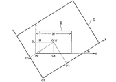
まず、画像データ取得部11が、記憶装置3などから画像データを取得し、これを画像表示制御部25に与える。画像表示制御部25は、例えば、図2に示すように、画像データに基づく画像Gを画面Dに表示せる。
First, the image data acquisition unit 11 acquires image data from the
画面で予め定められた前述の点Oは、画面の中心に存在する。点Oの画面でのX座標はOx、Y座標はOyである。画面の高さをH、幅をWとすると、座標Ox=W/2、座標Oy=H/2である。画面での座標の原点D0は画面の左下端の点であり、画面での座標のX軸は右、Y軸は上方向に延びている。なお、点Oは画面の中心以外の点であってもよい。 The point O previously determined on the screen exists at the center of the screen. The X coordinate on the screen of the point O is Ox, and the Y coordinate is Oy. If the height of the screen is H and the width is W, coordinates Ox = W / 2 and coordinates Oy = H / 2. The origin D0 of the coordinates on the screen is a point at the lower left corner of the screen, and the X axis of the coordinates on the screen extends to the right and the Y axis extends upward. Note that the point O may be a point other than the center of the screen.
点Oに対応する画像での点O’のX座標はO’x、Y座標はO’yである。画像での座標の原点G0は画像の左下端の点であり、画像での座標のX軸は右方向、Y軸は上方向に延びている。画像は、画面に対し、反時計回りに角度θだけ傾いている。 The X coordinate of the point O ′ in the image corresponding to the point O is O′x, and the Y coordinate is O′y. The origin G0 of the coordinates in the image is a point at the lower left corner of the image, and the X axis of the coordinates in the image extends in the right direction and the Y axis extends in the upward direction. The image is inclined counterclockwise by an angle θ with respect to the screen.
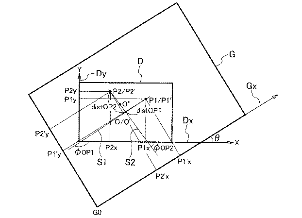
次に、マウスなどが操作され、図3に示すように、座標取得部12は、前述の第1の点P1の画面での座標と、前述の第2の点P2の画面での座標を取得し、第1の点P1の座標を角度距離算出部21に、第2の点P2の座標を角度距離算出部22にそれぞれ与える。
Next, the mouse or the like is operated, and as shown in FIG. 3, the
角度距離算出部21は、角度θを算出し、また、第1の点Pの座標を用いて、点Oと第1の点P1とを通過する直線S1と画面における座標のX軸Dxとでなす角度φOP1、点Oと第1の点P1との間の距離distOP1、点P1に対応する画像での点P1’の座標をそれぞれ算出し、これらの算出結果と画像での点O’の座標を基準情報記憶部31に記憶させる。
The angle
ここで、角度距離算出部21は、例えば、式(1)を用いて、角度φOP1を算出する。
ただし、式(1)におけるxは直線S1上に存在するベクトルのX軸Dx方向の成分、yは当該ベクトルのY軸Dy(画面における座標のY軸)方向の成分である。 However, x in the formula (1) is a component in the X-axis Dx direction of a vector existing on the straight line S1, and y is a component in the Y-axis Dy (Y-axis of coordinates on the screen) direction of the vector.
点P1の画面でのX座標をP1x、Y座標をP1y、点Oの画面でのX座標をOx、Y座標をOyとすると、例えば、X軸Dx方向の成分は、P1x−Oxであり、Y軸Dy方向の成分は、P1y−Oyである。 If the X coordinate on the screen of the point P1 is P1x, the Y coordinate is P1y, the X coordinate on the screen of the point O is Ox, and the Y coordinate is Oy, for example, the component in the X axis Dx direction is P1x-Ox, The component in the Y-axis Dy direction is P1y-Oy.
なお、角度φOP1を、直線S1とY軸Dyとでなす角度としてもよい。 The angle φ OP1 may be an angle formed by the straight line S1 and the Y axis Dy.
また、角度距離算出部21は、例えば、式(1)を用いて、角度θを算出する。
In addition, the angular
ただし、式(1)におけるxは画像における座標のX軸Gx上に存在するベクトルのX軸Dx方向の成分、yは当該ベクトルのY軸Dy(画面における座標のY軸)方向の成分である。 However, x in Expression (1) is a component in the X-axis Dx direction of a vector existing on the X-axis Gx of coordinates in the image, and y is a component in the Y-axis Dy (Y-axis of coordinates on the screen) direction of the vector. .
また、角度距離算出部21は、例えば、式(2)を用いて、距離distOP1を算出する。
ただし、式(2)におけるxは、点P1の画面でのX座標をP1x、点Oの画面でのX座標をOxとすると、P1x−Oxである。 However, x in the formula (2) is P1x−Ox, where X1 on the screen of the point P1 is P1x, and X on the screen of the point O is Ox.
また、式(2)におけるyは、点P1の画面でのY座標をP1y、点Oの画面でのX座標をOyとすると、P1y−Oyである。 Further, y in the expression (2) is P1y−Oy, where P1y is the Y coordinate on the screen of the point P1, and Oy is the X coordinate on the screen of the point O.
また、角度距離算出部21は、例えば、式(3)を用いて、点P1に対応する画像での点P1’の座標を算出する。
ただし、式(3)におけるP1’xは点P1’の画像でのX座標、P1’yは点P1’の画像でのY座標、O’xは点Oの画像でのX座標、O’yは点Oの画像でのy座標、θは画面に対する画像の反時計回りの傾きの角度である。 In Equation (3), P1′x is the X coordinate in the image of the point P1 ′, P1′y is the Y coordinate in the image of the point P1 ′, O′x is the X coordinate in the image of the point O, and O ′. y is the y coordinate in the image of the point O, and θ is the angle of the counterclockwise tilt of the image with respect to the screen.
一方、角度距離算出部22は、第2の点Pの座標を用いて、点Oと第2の点P2とを通過する直線S2と画面における座標のX軸Dxとでなす角度φOP2、点Oと第1の点P2との間の距離distOP2をそれぞれ算出し、角度φOP2を角度差分算出部24、距離distOP2を距離差分算出部23にそれぞれ与える。
On the other hand, the angle
ここで、角度距離算出部22は、例えば、式(1)を用いて、角度φOP2を算出する。
Here, the angular
ただし、式(1)におけるxは直線S2上に存在するベクトルのX軸Dx方向の成分、yは当該ベクトルのY軸Dy方向の成分である。 However, in Expression (1), x is a component in the X-axis Dx direction of a vector existing on the straight line S2, and y is a component in the Y-axis Dy direction of the vector.
点P2の画面でのX座標をP2x、Y座標をP2y、点Oの画面でのX座標をOx、Y座標をOyとすると、例えば、X軸Dx方向の成分は、P2x−Oxであり、Y軸Dy方向の成分は、P2y−Oyである。 If the X coordinate on the screen of the point P2 is P2x, the Y coordinate is P2y, the X coordinate on the screen of the point O is Ox, and the Y coordinate is Oy, for example, the component in the X-axis Dx direction is P2x-Ox, The component in the Y-axis Dy direction is P2y-Oy.
なお、角度φOP2を、直線S2とY軸Dyとでなす角度としてもよい。 The angle φ OP2 may be an angle formed by the straight line S2 and the Y axis Dy.
また、角度距離算出部22は、例えば、式(2)を用いて、距離distOP2を算出する。
Further, the angular
ただし、式(2)におけるxは、点P2の画面でのX座標をP2x、点Oの画面でのX座標をOxとすると、P2x−Oxである。 However, x in Expression (2) is P2x−Ox, where the X coordinate on the screen of the point P2 is P2x and the X coordinate on the screen of the point O is Ox.
また、式(2)におけるyは、点P2の画面でのY座標をP2y、点Oの画面でのX座標をOyとすると、P2y−Oyである。 Further, y in the expression (2) is P2y−Oy where the Y coordinate on the screen of the point P2 is P2y and the X coordinate on the screen of the point O is Oy.
座標算出部23は、基準情報記憶部31から距離distOP1、点P1’の座標(P1’x、P1’y)、画像での点O’の座標を読み出し、これらと与えられた距離distOP2を用い、例えば、式(4)により、点Oに対応する平行移動後の画像における点O’’の座標を算出し、これを画像表示制御部25に与える。
ただし、式(4)におけるO’’xは点O’’のX座標、O’’yは点O’’のY座標である。 In Equation (4), O ″ x is the X coordinate of the point O ″, and O ″ y is the Y coordinate of the point O ″.
角度算出部24は、基準情報記憶部31から角度θ、角度φOP1を読み出し、これらを与えられた角度φOP2を用い、例えば、式(5)により、回転後の画像の画面に対する反時計回りの傾きの角度θ’を算出し、これを画像表示制御部25に与える。
画像表示制御部25は、図4に示すように、点Oが点O’’に対応するように画像を平行移動させ、次に、画像の画面に対する反時計回りの角度θ’だけ傾くように画像を点O’’を中心に(点Oを中心に)回転させる。 As shown in FIG. 4, the image display control unit 25 translates the image so that the point O corresponds to the point O ″, and then tilts the image by a counterclockwise angle θ ′ with respect to the screen. Rotate the image around point O ″ (centered around point O).
本実施の形態によれば、例えば、図5(a)、(b)に示すように、ポインタCをドラッグして指定した点P1と点Oとを通過する直線上にP2があれば、角度θ’=0となり、画像は回転はせず、ドラックの方向(点Oから点P2の方向)に平行移動する。 According to the present embodiment, for example, as shown in FIGS. 5A and 5B, if there is P2 on a straight line passing through the points P1 and O specified by dragging the pointer C, the angle θ ′ = 0, and the image is not rotated, but is translated in the drag direction (from point O to point P2).
例えば、図5(a)に示すように、ポインタCを画面Dの右方向(または左方向)にドラックすれば、画像も同じ方向に平行移動する。また、例えば、図5(b)に示すように、ポインタCを画面Dの上方向(または下方向)にドラックすれば、画像も同じ方向に平行移動する。また、ポインタCを斜め方向にドラッグすれば、画像も同じ方向に平行移動する。 For example, as shown in FIG. 5A, when the pointer C is dragged in the right direction (or left direction) of the screen D, the image is also translated in the same direction. For example, as shown in FIG. 5B, if the pointer C is dragged upward (or downward) on the screen D, the image is also translated in the same direction. If the pointer C is dragged in an oblique direction, the image is also translated in the same direction.
また、例えば、図5(b)に示すように、ポインタCをドラッグして指定した点P1と点Oとを通過する直線に対して垂直な直線上に点P2があれば、角度θ’≠0となり、画像は回転する。例えば、ポインタCを点Oを中心として反時計回りにドラッグすれば、画像も同じ方向に回転する。 Further, for example, as shown in FIG. 5B, if there is a point P2 on a straight line perpendicular to the straight line passing through the point P1 and the point O specified by dragging the pointer C, the angle θ ′ ≠ 0 and the image rotates. For example, if the pointer C is dragged counterclockwise around the point O, the image is also rotated in the same direction.
以上説明したように、本実施の形態によれば、画像を移動させる操作と画像を回転させる操作を分けて行うことなく画像を移動および回転させることができる。よって、操作を分けることに伴う煩わしさを解消できる。 As described above, according to the present embodiment, an image can be moved and rotated without separately performing an operation for moving the image and an operation for rotating the image. Therefore, the troublesomeness associated with dividing the operation can be eliminated.
1 入力装置
2 中央処理制御装置
3 記憶装置
11 画像データ取得部
12 座標取得部
21、22 角度距離算出部
23 座標算出部
24 角度算出部
25 画像表示制御部
DESCRIPTION OF
Claims (4)
前記第1の点の座標を用いて、前記画面で予め定められた点と前記第1の点とを通過する直線と当該画面における座標の基準軸とでなす角度を算出し、前記予め定められた点と前記第1の点との間の距離を算出する角度距離算出部と、
前記第2の点の座標を用いて、前記予め定められた点と前記第2の点とを通過する直線と前記基準軸とでなす角度を算出し、前記予め定められた点と前記第2の点との間の距離を算出する角度距離算出部と、
前記画像を前記2つの距離の差分に応じた距離だけ平行移動させ、前記画像を前記2つの角度の差分に応じた角度だけ回転させる画像表示制御部と
を備えることを特徴とする画像表示装置。 A coordinate acquisition unit that acquires the coordinates of the two points specified in the screen on which the image is displayed;
Using the coordinates of the first point, an angle formed by a straight line passing through the point predetermined on the screen and the first point and a reference axis of the coordinate on the screen is calculated, and the predetermined point is calculated. An angular distance calculation unit for calculating a distance between the measured point and the first point;
Using the coordinates of the second point, an angle formed by a straight line passing through the predetermined point and the second point and the reference axis is calculated, and the predetermined point and the second point are calculated. An angular distance calculation unit for calculating a distance between the points,
An image display apparatus comprising: an image display controller configured to translate the image by a distance corresponding to the difference between the two distances and rotate the image by an angle corresponding to the difference between the two angles.
前記画像表示装置は、前記画面に表示されるポインタを動かすために用いられ且つ当該ポインタが前記画面に表示されているときに操作される操作部を備える入力装置ととともに使用されるものであり、
前記座標取得部は、
前記操作部への操作が開始されたときに前記ポインタが存在する前記第1の点の座標と前記操作部への操作が終了したときに前記ポインタが存在する前記第2の点の座標とを取得することを特徴とする画像表示装置。 The image display device according to claim 1,
The image display device is used together with an input device that is used to move a pointer displayed on the screen and includes an operation unit that is operated when the pointer is displayed on the screen.
The coordinate acquisition unit
The coordinates of the first point where the pointer exists when the operation to the operation unit is started and the coordinates of the second point where the pointer exists when the operation to the operation unit ends. An image display device characterized by being obtained.
前記第1の点の座標を用いて、前記予め定められた点と前記第1の点とを通過する直線と当該画面における座標の基準軸とでなす角度を算出し、前記予め定められた点と前記第1の点との間の距離を算出するステップと、
前記第2の点の座標を用いて、前記画面内の前記予め定められた点と前記第2の点とを通過する直線と前記基準軸とでなす角度を算出し、前記予め定められた点と前記第2の点との間の距離を算出するステップと、
前記画像を前記2つの距離の差分に応じた距離だけ平行移動させ、前記画像を前記2つの角度の差分に応じた角度だけ回転させるステップと
を含むことを特徴とする画像表示方法。 Obtaining the coordinates of the two points specified in the screen on which the image is displayed;
Using the coordinates of the first point, an angle formed by a straight line passing through the predetermined point and the first point and a reference axis of coordinates on the screen is calculated, and the predetermined point is calculated. Calculating a distance between the first point and the first point;
By using the coordinates of the second point, an angle formed between the predetermined point in the screen and the straight line passing through the second point and the reference axis is calculated, and the predetermined point is calculated. Calculating a distance between the second point and the second point;
Translating the image by a distance according to the difference between the two distances and rotating the image by an angle according to the difference between the two angles.
Priority Applications (1)
| Application Number | Priority Date | Filing Date | Title |
|---|---|---|---|
| JP2009202400A JP5055331B2 (en) | 2009-09-02 | 2009-09-02 | Image display device and image display method |
Applications Claiming Priority (1)
| Application Number | Priority Date | Filing Date | Title |
|---|---|---|---|
| JP2009202400A JP5055331B2 (en) | 2009-09-02 | 2009-09-02 | Image display device and image display method |
Publications (2)
| Publication Number | Publication Date |
|---|---|
| JP2011053924A JP2011053924A (en) | 2011-03-17 |
| JP5055331B2 true JP5055331B2 (en) | 2012-10-24 |
Family
ID=43942854
Family Applications (1)
| Application Number | Title | Priority Date | Filing Date |
|---|---|---|---|
| JP2009202400A Expired - Fee Related JP5055331B2 (en) | 2009-09-02 | 2009-09-02 | Image display device and image display method |
Country Status (1)
| Country | Link |
|---|---|
| JP (1) | JP5055331B2 (en) |
Family Cites Families (4)
| Publication number | Priority date | Publication date | Assignee | Title |
|---|---|---|---|---|
| JPH04304571A (en) * | 1991-04-01 | 1992-10-27 | Canon Inc | Image processing device |
| JPH11288460A (en) * | 1998-04-02 | 1999-10-19 | Sony Corp | Display screen movement control device and electronic device having the same |
| JP4080125B2 (en) * | 2000-01-21 | 2008-04-23 | 正昭 宮田 | Information processing apparatus and mouse |
| JP4897411B2 (en) * | 2006-09-26 | 2012-03-14 | 任天堂株式会社 | Information processing program and information processing apparatus |
-
2009
- 2009-09-02 JP JP2009202400A patent/JP5055331B2/en not_active Expired - Fee Related
Also Published As
| Publication number | Publication date |
|---|---|
| JP2011053924A (en) | 2011-03-17 |
Similar Documents
| Publication | Publication Date | Title |
|---|---|---|
| JP6534974B2 (en) | System and method for providing an efficient interface for screen control | |
| CN105190509B (en) | Provides content rotation during scrolling action | |
| CN102375539A (en) | Information processing device, information processing method, and program | |
| JP6110893B2 (en) | Virtual space location designation method, program, recording medium recording program, and apparatus | |
| US11158130B1 (en) | Systems for augmented reality sketching | |
| US20230418431A1 (en) | Interactive three-dimensional representations of objects | |
| US9508188B2 (en) | Re-centering a view of a scene of a three-dimensional image of anatomy of interest and an alignment object based on a new location of the alignment object in the three-dimensional image | |
| JP6141290B2 (en) | Interaction by acceleration of multi-pointer indirect input device | |
| US10281804B2 (en) | Image processing apparatus, image processing method, and program | |
| US10102310B2 (en) | Precise object manipulation system and method | |
| JP5055331B2 (en) | Image display device and image display method | |
| JP5108848B2 (en) | Image display device and image display method | |
| JP2021124433A (en) | Measurement device, measurement program and measurement method | |
| JP2009193471A (en) | Display control device, display processing device, application server, display control method, display processing method, application execution method, control program, and recording medium | |
| JP2016076017A (en) | Graphic processing apparatus and graphic processing program | |
| JP6488946B2 (en) | Control method, program, and control apparatus | |
| JP6252184B2 (en) | Gesture input device, gesture input method and program | |
| JP2016031614A (en) | Information processing apparatus, information processing method, information processing system, and program | |
| JP2016153996A (en) | Coordinate acquisition system, display device, coordinate acquisition method, and program | |
| EP3295291B1 (en) | Drawing object inferring system and method | |
| JP6873326B2 (en) | Eye 3D coordinate acquisition device and gesture operation device | |
| KR101472314B1 (en) | 3D Input Method and Apparatus using Single Camera | |
| US20090248353A1 (en) | System and method for simulating movement of an image measuring machine | |
| JP6192157B2 (en) | Measuring device and program thereof | |
| US20160110894A1 (en) | Method and apparatus to render lines on a display screen |
Legal Events
| Date | Code | Title | Description |
|---|---|---|---|
| A621 | Written request for application examination |
Free format text: JAPANESE INTERMEDIATE CODE: A621 Effective date: 20110902 |
|
| RD03 | Notification of appointment of power of attorney |
Free format text: JAPANESE INTERMEDIATE CODE: A7423 Effective date: 20120510 |
|
| RD04 | Notification of resignation of power of attorney |
Free format text: JAPANESE INTERMEDIATE CODE: A7424 Effective date: 20120514 |
|
| A977 | Report on retrieval |
Free format text: JAPANESE INTERMEDIATE CODE: A971007 Effective date: 20120622 |
|
| TRDD | Decision of grant or rejection written | ||
| A01 | Written decision to grant a patent or to grant a registration (utility model) |
Free format text: JAPANESE INTERMEDIATE CODE: A01 Effective date: 20120724 |
|
| A01 | Written decision to grant a patent or to grant a registration (utility model) |
Free format text: JAPANESE INTERMEDIATE CODE: A01 |
|
| A61 | First payment of annual fees (during grant procedure) |
Free format text: JAPANESE INTERMEDIATE CODE: A61 Effective date: 20120730 |
|
| R150 | Certificate of patent or registration of utility model |
Ref document number: 5055331 Country of ref document: JP Free format text: JAPANESE INTERMEDIATE CODE: R150 Free format text: JAPANESE INTERMEDIATE CODE: R150 |
|
| FPAY | Renewal fee payment (event date is renewal date of database) |
Free format text: PAYMENT UNTIL: 20150803 Year of fee payment: 3 |
|
| S531 | Written request for registration of change of domicile |
Free format text: JAPANESE INTERMEDIATE CODE: R313531 |
|
| R350 | Written notification of registration of transfer |
Free format text: JAPANESE INTERMEDIATE CODE: R350 |
|
| LAPS | Cancellation because of no payment of annual fees |