JP5056808B2 - Hard coating tool - Google Patents
Hard coating tool Download PDFInfo
- Publication number
- JP5056808B2 JP5056808B2 JP2009159274A JP2009159274A JP5056808B2 JP 5056808 B2 JP5056808 B2 JP 5056808B2 JP 2009159274 A JP2009159274 A JP 2009159274A JP 2009159274 A JP2009159274 A JP 2009159274A JP 5056808 B2 JP5056808 B2 JP 5056808B2
- Authority
- JP
- Japan
- Prior art keywords
- hard
- film
- hard film
- hard coating
- compressive stress
- Prior art date
- Legal status (The legal status is an assumption and is not a legal conclusion. Google has not performed a legal analysis and makes no representation as to the accuracy of the status listed.)
- Active
Links
- 238000000576 coating method Methods 0.000 title claims description 129
- 239000011248 coating agent Substances 0.000 title claims description 122
- IJGRMHOSHXDMSA-UHFFFAOYSA-N Atomic nitrogen Chemical compound N#N IJGRMHOSHXDMSA-UHFFFAOYSA-N 0.000 claims description 40
- 239000013078 crystal Substances 0.000 claims description 40
- 239000000203 mixture Substances 0.000 claims description 37
- 239000000758 substrate Substances 0.000 claims description 31
- QVGXLLKOCUKJST-UHFFFAOYSA-N atomic oxygen Chemical compound [O] QVGXLLKOCUKJST-UHFFFAOYSA-N 0.000 claims description 26
- 239000001301 oxygen Substances 0.000 claims description 26
- 229910052760 oxygen Inorganic materials 0.000 claims description 26
- 239000010936 titanium Substances 0.000 claims description 22
- 229910052757 nitrogen Inorganic materials 0.000 claims description 20
- OKTJSMMVPCPJKN-UHFFFAOYSA-N Carbon Chemical group [C] OKTJSMMVPCPJKN-UHFFFAOYSA-N 0.000 claims description 19
- 229910052799 carbon Inorganic materials 0.000 claims description 19
- 238000002441 X-ray diffraction Methods 0.000 claims description 17
- 229910052796 boron Inorganic materials 0.000 claims description 15
- 229910052710 silicon Inorganic materials 0.000 claims description 13
- 229910052751 metal Inorganic materials 0.000 claims description 12
- 239000002184 metal Substances 0.000 claims description 12
- 229910052719 titanium Inorganic materials 0.000 claims description 9
- XUIMIQQOPSSXEZ-UHFFFAOYSA-N Silicon Chemical group [Si] XUIMIQQOPSSXEZ-UHFFFAOYSA-N 0.000 claims description 8
- 239000010703 silicon Substances 0.000 claims description 8
- ZOXJGFHDIHLPTG-UHFFFAOYSA-N Boron Chemical group [B] ZOXJGFHDIHLPTG-UHFFFAOYSA-N 0.000 claims description 7
- RTAQQCXQSZGOHL-UHFFFAOYSA-N Titanium Chemical compound [Ti] RTAQQCXQSZGOHL-UHFFFAOYSA-N 0.000 claims description 7
- 229910052782 aluminium Inorganic materials 0.000 claims description 4
- XAGFODPZIPBFFR-UHFFFAOYSA-N aluminium Chemical compound [Al] XAGFODPZIPBFFR-UHFFFAOYSA-N 0.000 claims description 4
- 239000007888 film coating Substances 0.000 claims 1
- 238000009501 film coating Methods 0.000 claims 1
- 239000010408 film Substances 0.000 description 253
- 238000005520 cutting process Methods 0.000 description 58
- 230000000052 comparative effect Effects 0.000 description 34
- 230000015572 biosynthetic process Effects 0.000 description 20
- 238000012360 testing method Methods 0.000 description 19
- 238000006243 chemical reaction Methods 0.000 description 16
- 238000000034 method Methods 0.000 description 15
- 150000002500 ions Chemical class 0.000 description 14
- 239000007789 gas Substances 0.000 description 13
- 230000007547 defect Effects 0.000 description 12
- 238000003466 welding Methods 0.000 description 12
- 239000000463 material Substances 0.000 description 10
- 230000003647 oxidation Effects 0.000 description 9
- 238000007254 oxidation reaction Methods 0.000 description 9
- 230000007423 decrease Effects 0.000 description 8
- 238000005461 lubrication Methods 0.000 description 8
- XKRFYHLGVUSROY-UHFFFAOYSA-N Argon Chemical compound [Ar] XKRFYHLGVUSROY-UHFFFAOYSA-N 0.000 description 6
- ATJFFYVFTNAWJD-UHFFFAOYSA-N Tin Chemical compound [Sn] ATJFFYVFTNAWJD-UHFFFAOYSA-N 0.000 description 6
- 150000004767 nitrides Chemical class 0.000 description 6
- 239000000523 sample Substances 0.000 description 6
- 230000006866 deterioration Effects 0.000 description 5
- 230000000694 effects Effects 0.000 description 5
- 238000011156 evaluation Methods 0.000 description 5
- 238000005240 physical vapour deposition Methods 0.000 description 5
- PZNSFCLAULLKQX-UHFFFAOYSA-N Boron nitride Chemical compound N#B PZNSFCLAULLKQX-UHFFFAOYSA-N 0.000 description 4
- 239000004215 Carbon black (E152) Substances 0.000 description 4
- MYMOFIZGZYHOMD-UHFFFAOYSA-N Dioxygen Chemical compound O=O MYMOFIZGZYHOMD-UHFFFAOYSA-N 0.000 description 4
- 238000005299 abrasion Methods 0.000 description 4
- 229910001882 dioxygen Inorganic materials 0.000 description 4
- 229930195733 hydrocarbon Natural products 0.000 description 4
- 150000002430 hydrocarbons Chemical class 0.000 description 4
- VNWKTOKETHGBQD-UHFFFAOYSA-N methane Chemical compound C VNWKTOKETHGBQD-UHFFFAOYSA-N 0.000 description 4
- 229910052582 BN Inorganic materials 0.000 description 3
- 229910052786 argon Inorganic materials 0.000 description 3
- 239000011651 chromium Substances 0.000 description 3
- 239000000470 constituent Substances 0.000 description 3
- 238000009792 diffusion process Methods 0.000 description 3
- 229910001873 dinitrogen Inorganic materials 0.000 description 3
- 238000004519 manufacturing process Methods 0.000 description 3
- 238000005259 measurement Methods 0.000 description 3
- 239000010955 niobium Substances 0.000 description 3
- 238000012545 processing Methods 0.000 description 3
- 229910001315 Tool steel Inorganic materials 0.000 description 2
- 230000001133 acceleration Effects 0.000 description 2
- 229910045601 alloy Inorganic materials 0.000 description 2
- 239000000956 alloy Substances 0.000 description 2
- 229910052804 chromium Inorganic materials 0.000 description 2
- 150000001875 compounds Chemical class 0.000 description 2
- 230000001276 controlling effect Effects 0.000 description 2
- 230000008020 evaporation Effects 0.000 description 2
- 238000001704 evaporation Methods 0.000 description 2
- 239000012535 impurity Substances 0.000 description 2
- 238000007733 ion plating Methods 0.000 description 2
- 229910052758 niobium Inorganic materials 0.000 description 2
- 239000006104 solid solution Substances 0.000 description 2
- 239000013077 target material Substances 0.000 description 2
- 229910052721 tungsten Inorganic materials 0.000 description 2
- -1 AlN compound Chemical class 0.000 description 1
- VYZAMTAEIAYCRO-UHFFFAOYSA-N Chromium Chemical compound [Cr] VYZAMTAEIAYCRO-UHFFFAOYSA-N 0.000 description 1
- VGGSQFUCUMXWEO-UHFFFAOYSA-N Ethene Chemical compound C=C VGGSQFUCUMXWEO-UHFFFAOYSA-N 0.000 description 1
- 239000005977 Ethylene Substances 0.000 description 1
- 229910052774 Proactinium Inorganic materials 0.000 description 1
- NRTOMJZYCJJWKI-UHFFFAOYSA-N Titanium nitride Chemical compound [Ti]#N NRTOMJZYCJJWKI-UHFFFAOYSA-N 0.000 description 1
- 238000004458 analytical method Methods 0.000 description 1
- 230000005540 biological transmission Effects 0.000 description 1
- 230000003139 buffering effect Effects 0.000 description 1
- 239000011195 cermet Substances 0.000 description 1
- 239000008199 coating composition Substances 0.000 description 1
- 239000002131 composite material Substances 0.000 description 1
- 230000006835 compression Effects 0.000 description 1
- 238000007906 compression Methods 0.000 description 1
- 230000002596 correlated effect Effects 0.000 description 1
- 230000000875 corresponding effect Effects 0.000 description 1
- 239000010730 cutting oil Substances 0.000 description 1
- 230000003247 decreasing effect Effects 0.000 description 1
- 230000007812 deficiency Effects 0.000 description 1
- 238000000151 deposition Methods 0.000 description 1
- 230000008021 deposition Effects 0.000 description 1
- 238000001514 detection method Methods 0.000 description 1
- 238000010891 electric arc Methods 0.000 description 1
- 238000004453 electron probe microanalysis Methods 0.000 description 1
- 238000010438 heat treatment Methods 0.000 description 1
- 239000011261 inert gas Substances 0.000 description 1
- 238000011835 investigation Methods 0.000 description 1
- 238000010030 laminating Methods 0.000 description 1
- 238000000691 measurement method Methods 0.000 description 1
- 239000012528 membrane Substances 0.000 description 1
- GUCVJGMIXFAOAE-UHFFFAOYSA-N niobium atom Chemical compound [Nb] GUCVJGMIXFAOAE-UHFFFAOYSA-N 0.000 description 1
- 229910052755 nonmetal Inorganic materials 0.000 description 1
- 230000003287 optical effect Effects 0.000 description 1
- 230000001737 promoting effect Effects 0.000 description 1
- 239000012495 reaction gas Substances 0.000 description 1
- 102220097517 rs876659265 Human genes 0.000 description 1
- 238000004544 sputter deposition Methods 0.000 description 1
- 230000006641 stabilisation Effects 0.000 description 1
- 238000011105 stabilization Methods 0.000 description 1
- 239000010409 thin film Substances 0.000 description 1
- WFKWXMTUELFFGS-UHFFFAOYSA-N tungsten Chemical compound [W] WFKWXMTUELFFGS-UHFFFAOYSA-N 0.000 description 1
- 239000010937 tungsten Substances 0.000 description 1
- UONOETXJSWQNOL-UHFFFAOYSA-N tungsten carbide Chemical compound [W+]#[C-] UONOETXJSWQNOL-UHFFFAOYSA-N 0.000 description 1
Landscapes
- Cutting Tools, Boring Holders, And Turrets (AREA)
- Physical Vapour Deposition (AREA)
Description
本発明は、金属部品加工等に用いられる硬質皮膜被覆工具に関するものである。特に、耐摩耗性と密着性が必要とされる工具表面に、物理蒸着(以下、PVD法と記す。)を用いて硬質皮膜を被覆した硬質皮膜被覆工具に関する。 The present invention relates to a hard film-coated tool used for processing metal parts and the like. In particular, the present invention relates to a hard film-coated tool in which a hard film is coated on a tool surface that requires wear resistance and adhesion using physical vapor deposition (hereinafter referred to as PVD method).
特許文献1、2には、PVD法により被覆した硬質皮膜のX線回折における(200)面の配向性と回折ピークの半価幅について開示されている。特許文献3には、PVD法により被覆した硬質皮膜のX線回折における(111)面の配向性と回折ピークの半価幅について開示されている。特許文献4には、(220)面、(111)面のピーク強度を制御する技術が開示されている。特許文献5には、硬質皮膜を構成する金属元素とガス成分元素の構成比率を調整する技術が開示されている。特許文献6には、エピタキシャル成長により皮膜界面の密着性改善に関する技術が開示されている。 Patent Documents 1 and 2 disclose the orientation of the (200) plane and the half-value width of the diffraction peak in X-ray diffraction of a hard film coated by the PVD method. Patent Document 3 discloses the orientation of the (111) plane and the half-value width of the diffraction peak in X-ray diffraction of a hard film coated by the PVD method. Patent Document 4 discloses a technique for controlling peak intensities on the (220) plane and the (111) plane. Patent Document 5 discloses a technique for adjusting the constituent ratio of a metal element and a gas component element constituting a hard coating. Patent Document 6 discloses a technique related to improvement in adhesion at a film interface by epitaxial growth.
しかし、特許文献1〜6のいずれにも、本発明に係る、Alを含有する第1硬質皮膜と(TiB)N系第2硬質皮膜とを積層して構成される硬質皮膜であって、当該硬質皮膜について組成、X線配向及びミクロ組織等を適宜に選択、制御することによって、工具寿命等を顕著に向上させるようにしたことは何ら記載されておらず、示唆もされていない、 However, in any of Patent Documents 1 to 6, the present invention is a hard film constituted by laminating a first hard film containing Al and a (TiB) N-based second hard film according to the present invention, The composition, X-ray orientation and microstructure of the hard film are appropriately selected and controlled to notably improve or improve the tool life and the like.
従って、本発明は、厚膜化した硬質皮膜における圧縮応力の低減により密着性を高め、かつ硬質皮膜表面の高硬度化により耐摩耗性に優れた新規高性能な硬質皮膜被覆工具を提供することを目的とする。 Accordingly, the present invention provides a new high-performance hard film-coated tool that improves adhesion by reducing the compressive stress in a hard film that has been thickened, and has excellent wear resistance by increasing the hardness of the hard film surface. With the goal.
本発明の硬質皮膜被覆工具は、超硬合金を基体に圧縮応力を有する硬質皮膜を5〜30μmの膜厚で被覆した硬質皮膜被覆工具において、該硬質皮膜は該基体表面から第1硬質皮膜及び第2硬質皮膜が被覆され、最外皮膜は該第2硬質皮膜が被覆される。 該第1硬質皮膜の組成は、(AlaMe100−a)eNf(但し、aは原子%であり、e及びfは夫々原子比を表し、35≦a≦65、及び0.85≦e/f≦1.25であり、Alはアルミニウムであり、Meは4a、5a、6a族、Si及びBから選択される少なくとも1種の元素であり、Nは窒素である。)で表され、
該第2硬質皮膜の組成は、(Ti100−hBh)mNp(但し、hは原子%であり、m及びpは夫々原子比を表し、0<h≦30、及び0.90≦m/p≦1.15であり、Tiはチタニウムであり、Bは硼素であり、Nは窒素である。)で表され、
該第1硬質皮膜、及び該第2硬質皮膜の結晶構造は夫々面心立方構造であり、
(111)面のピーク強度をIr、(200)面のピーク強度をIs、及び(220)面のピーク強度をItとしたときに、該第1硬質皮膜のX線回折において1.5≦Is/Ir≦15.0、及び0.6≦It/Ir≦1.5であり、該第2硬質皮膜のX線回折において0.2≦Is/Ir≦1.0、及び0.6≦It/Is≦1.5であり、
該第1硬質皮膜と該第2硬質皮膜のX線回折において、最も強度の高い面における面間隔(nm)を夫々d1、d2としたときに、1.00≦d2/d1≦1.03であり、
該第2硬質皮膜は柱状組織を有し、該柱状組織の結晶粒はB成分に組成差を有する組成変調構造を有することを特徴とする。
本発明によれば、厚膜化した硬質皮膜における圧縮応力の低減により密着性を高め、かつ硬質皮膜表面の高硬度化による耐摩耗性に優れた硬質皮膜被覆工具を提供することができる。The hard film coated tool of the present invention is a hard film coated tool in which a hard film having a compressive stress is coated on a substrate with a cemented carbide alloy in a film thickness of 5 to 30 μm. The second hard film is coated, and the outermost film is coated with the second hard film. The composition of the first hard coating is (Al a Me 100-a ) e N f (where a is atomic%, e and f represent atomic ratios, respectively 35 ≦ a ≦ 65, and 0.85) ≦ e / f ≦ 1.25, Al is aluminum, Me is at least one element selected from groups 4a, 5a, and 6a, Si and B, and N is nitrogen. And
The composition of the second hard coating is (Ti 100-h B h ) m N p (where h is atomic%, m and p represent atomic ratios, respectively, 0 <h ≦ 30, and 0.90) ≦ m / p ≦ 1.15, Ti is titanium, B is boron, and N is nitrogen.)
The crystal structures of the first hard film and the second hard film are face-centered cubic structures, respectively.
When the peak intensity of the (111) plane is Ir, the peak intensity of the (200) plane is Is, and the peak intensity of the (220) plane is It, 1.5 ≦ Is in the X-ray diffraction of the first hard film. /Ir≦15.0 and 0.6 ≦ It / Ir ≦ 1.5, and in the X-ray diffraction of the second hard film, 0.2 ≦ Is / Ir ≦ 1.0 and 0.6 ≦ It /Is≦1.5,
In the X-ray diffraction of the first hard film and the second hard film, 1.00 ≦ d2 / d1 ≦ 1.03, where d1 and d2 are plane distances (nm) on the surface having the highest intensity, respectively. Yes,
The second hard film has a columnar structure, and the crystal grains of the columnar structure have a composition modulation structure having a composition difference in the B component.
According to the present invention, it is possible to provide a hard film-coated tool that has improved adhesion by reducing compressive stress in a hard film that has been increased in thickness, and that has excellent wear resistance due to increased hardness of the surface of the hard film.
本発明の硬質膜被覆工具において、該第1硬質皮膜における非金属成分の窒素(N)について、その一部を炭素(C)及び/または酸素(O)で置換し、該非金属成分全体を100原子%とし、原子%で炭素の含有量をx、酸素の含有量をyとしたとき、0<x≦10、0<y≦10、0<x+y≦10、及び窒素の含有量は(100−x−y)であることが好ましい。
また、該第2硬質皮膜における金属成分のチタニウム(Ti)について、その一部を珪素(Si)で置換し、該金属成分全体を100原子%とし、原子%でシリコンの含有量をkとしたとき、0<k≦20、及びチタニウムの含有量は(100−h−k)であることが好ましい。圧縮応力を有する該硬質皮膜は10μm〜30μmの総膜厚であることが好ましい。In the hard film-coated tool of the present invention, a part of the nonmetallic component nitrogen (N) in the first hard coating is replaced with carbon (C) and / or oxygen (O), and the entire nonmetallic component is 100%. Assuming that the atomic% is carbon content and the oxygen content is x and the oxygen content is y, 0 <x ≦ 10, 0 <y ≦ 10, 0 <x + y ≦ 10, and the nitrogen content is (100 -Xy) is preferred.
Further, a part of the metal component titanium (Ti) in the second hard film is replaced with silicon (Si), the entire metal component is 100 atomic%, and the silicon content is k in atomic%. When 0 <k ≦ 20, the content of titanium is preferably (100−h−k). The hard film having a compressive stress preferably has a total film thickness of 10 μm to 30 μm.
本発明によって、厚膜化した硬質皮膜における圧縮応力の低減により密着性を高め、かつ、硬質皮膜表面の高硬度化による耐摩耗性に優れた硬質皮膜被覆工具を提供することができる。 According to the present invention, it is possible to provide a hard film-coated tool having improved adhesion by reducing the compressive stress in a hard film having a thick film and having excellent wear resistance by increasing the hardness of the surface of the hard film.
本発明の硬質皮膜被覆工具が採用する硬質皮膜は第1硬質皮膜及び第2硬質皮膜を有して構成される。 The hard film employed by the hard film-coated tool of the present invention has a first hard film and a second hard film.
<第1硬質皮膜>
第1硬質皮膜の組成は、(AlaMe100−a)eNfで示される。
前記組成式において、カッコ内はAlとMe元素との比率を原子%により表示し、カッコ外は(AlMe)とNとの比率を原子比により表示している。アルミニウム(Al)含有量を表すa値が35≦a≦65原子%の範囲のとき、耐熱性、耐摩耗性が優れる。a値が65原子%を超えて大きいと、第1皮膜断面組織が微細化して圧縮応力が増大し、基体との密着性が劣化する不都合が生じる。a値が35原子%未満であると、耐摩耗性が劣ると言う不都合が生じる。
元素をMeとして集合的に呼称するMe成分は、イオン半径が0.041〜0.1nmの4a、5a、6a族の元素や、イオン半径が0.002〜0.04nmの珪素(Si)、硼素(B)等を含有した窒化物として被覆することが好ましい。この理由は、Me成分、珪素や硼素のイオン半径と、アルミニウム元素のイオン半径との間に差が生じ、結晶構造に応力が作用して、皮膜の高硬度化に好都合だからである。Me成分として、例えばチタニウム(Ti)を選択することにより、第1硬質皮膜の高硬度化に有効である。また、例えばMeが珪素(Si)、硼素(B)では、固溶体を維持する含有量の範囲が1原子%から20原子%であり、優れた耐熱性や潤滑特性を得られる。また、MeとしてW、NbまたはCrを含有することにより、第1硬質皮膜の耐熱性、高硬度化の改善に有効である。<First hard coating>
The composition of the first hard coating is represented by (Al a Me 100-a ) e N f .
In the composition formula, the ratio between Al and Me elements is indicated in atomic percent in parentheses, and the ratio between (AlMe) and N is indicated in atomic ratios outside the parentheses. When the value a representing the aluminum (Al) content is in the range of 35 ≦ a ≦ 65 atomic%, the heat resistance and wear resistance are excellent. If the a value exceeds 65 atomic%, the first film cross-sectional structure becomes finer, the compressive stress increases, and there is a disadvantage that the adhesion with the substrate deteriorates. When the a value is less than 35 atomic%, there is a disadvantage that the wear resistance is inferior.
The Me component collectively referred to as the element Me includes elements 4a, 5a, and 6a having an ionic radius of 0.041 to 0.1 nm, silicon (Si) having an ionic radius of 0.002 to 0.04 nm, It is preferable to coat as a nitride containing boron (B) or the like. This is because there is a difference between the ionic radius of the Me component, silicon or boron, and the ionic radius of the aluminum element, and stress acts on the crystal structure, which is convenient for increasing the hardness of the film. By selecting, for example, titanium (Ti) as the Me component, it is effective for increasing the hardness of the first hard coating. For example, when Me is silicon (Si) or boron (B), the content range for maintaining the solid solution is 1 to 20 atomic%, and excellent heat resistance and lubrication characteristics can be obtained. In addition, containing W, Nb or Cr as Me is effective in improving the heat resistance and hardness of the first hard coating.
第1硬質皮膜の金属成分と非金属成分との比e/f値を0.85〜1.25とすることにより、硬質皮膜の圧縮応力を最適な範囲にすることができ、極めて高い密着性を得ることができる。また、e/f値を0.85〜1.25とすると、第1硬質皮膜の組織は高靭性を有する柱状組織とすることができ、優れた欠損性と耐摩耗性を得ることができる。e/f値が0.85以上のとき、第1硬質皮膜の結晶格子歪を低減できるが、0.85未満になると、結晶格子歪が大きくなり、結晶格子縞の連続性が失われる現象や、第1硬質皮膜の断面組織が微細化し結晶粒界欠陥が増大する。その結果、圧縮応力が増大して密着性が劣化する。例えば、切削工具用の硬質皮膜においては、この粒界欠陥が硬質皮膜の密度低下や、被加工物を構成する元素が、この粒界に進入して硬質皮膜内部への内向拡散を招き、硬質皮膜の硬度低下や、耐酸化性、耐欠損性といった、硬質皮膜の機械的特性を著しく劣化させる。e/f値が1.25を超えると第1硬質皮膜は柱状組織を有するが、結晶の粒界部に不純物を取り込みやすくなる。この不純物は被覆処理を行う装置内部に残留する成分である。その結果、結晶粒間の接合強度が劣化し、第1硬質皮膜は外部からの衝撃によって容易に破壊したり、被加工物を構成する元素が、この粒界に進入して硬質皮膜内部への内向拡散を招き、硬質皮膜の硬度低下や、耐酸化性といった機械的特性の劣化を招く。本発明の第1硬質皮膜は、0.85≦e/f≦1.25の範囲とすることにより、第1硬質皮膜の圧縮応力は1.5〜5.0GPaの範囲になる。産業的には、e/r値を本発明の範囲にすることで、第1硬質皮膜に圧縮応力を有しつつ、かつその圧縮応力が過度ではない範囲に管理することが可能である。 By setting the ratio e / f value between the metal component and the non-metal component of the first hard coating to 0.85 to 1.25, the compressive stress of the hard coating can be adjusted to an optimum range, and extremely high adhesion Can be obtained. Further, when the e / f value is 0.85 to 1.25, the structure of the first hard film can be a columnar structure having high toughness, and excellent chipping and wear resistance can be obtained. When the e / f value is 0.85 or more, the crystal lattice strain of the first hard film can be reduced. However, when the e / f value is less than 0.85, the crystal lattice strain increases and the continuity of crystal lattice fringes is lost. The cross-sectional structure of the first hard coating becomes finer and the grain boundary defects increase. As a result, the compressive stress increases and the adhesion deteriorates. For example, in hard coatings for cutting tools, this grain boundary defect reduces the density of the hard coating, and the elements that make up the workpiece enter this grain boundary and cause inward diffusion into the hard coating. It significantly deteriorates the mechanical properties of the hard film, such as a decrease in film hardness, oxidation resistance, and fracture resistance. When the e / f value exceeds 1.25, the first hard film has a columnar structure, but it is easy to incorporate impurities into the crystal grain boundary. This impurity is a component remaining inside the apparatus that performs the coating process. As a result, the bonding strength between the crystal grains deteriorates, and the first hard film is easily broken by an external impact, or the elements constituting the workpiece enter the grain boundary and enter the hard film. Inward diffusion is caused, resulting in a decrease in the hardness of the hard coating and deterioration in mechanical properties such as oxidation resistance. By setting the first hard coating of the present invention in the range of 0.85 ≦ e / f ≦ 1.25, the compressive stress of the first hard coating is in the range of 1.5 to 5.0 GPa. Industrially, by setting the e / r value within the range of the present invention, it is possible to manage the first hard coating within a range where the compressive stress is not excessive while having the compressive stress.
<第2硬質皮膜>
第2硬質皮膜の組成は、(Ti100−hBh)mNpで示される。
前記組成式において、カッコ内はTiとBとの比率を原子%により表示し、カッコ外は(TiB)とNとの比率を原子比により表示している。第2硬質皮膜が、Ti及びBを含有する面心立方構造の窒化物であることにより、優れた耐溶着性と耐クレータ摩耗性を実現できる。第2硬質皮膜におけるB含有量を示すh値(原子%)は0<h≦30でり、1≦h≦30とするのが好ましい。h値のこの範囲は第2硬質皮膜を柱状組織とするために重要である。またB元素を含有させると、工具のすくい面の耐摩耗特性が向上する。切削初期において、Bは工具刃先がまだ低温である状態から酸化され、B含有酸化物を形成する。このB含有酸化物が、被加工物成分の第2硬質皮膜内部への拡散を抑制させる効果を発揮する。しかし、h値が30原子%を超えると、第2硬質皮膜の組織が微細化する。また、窒化硼素(BN)の結晶が出現し硬度が低下し、第2硬質皮膜の圧縮応力が増大して密着性が低下する欠点が現れる。h値は、1原子%程度でも効果が現れる。<Second hard coating>
The composition of the second hard coating is represented by (Ti 100-h B h ) m N p .
In the composition formula, the ratio between Ti and B is expressed in atomic% inside the parentheses, and the ratio between (TiB) and N is expressed by atomic ratio outside the parentheses. When the second hard film is a nitride having a face-centered cubic structure containing Ti and B, excellent welding resistance and crater wear resistance can be realized. The h value (atomic%) indicating the B content in the second hard film is 0 <h ≦ 30, and preferably 1 ≦ h ≦ 30. This range of h values is important for making the second hard coating a columnar structure. Moreover, when B element is contained, the wear resistance of the rake face of the tool is improved. In the initial stage of cutting, B is oxidized from the state where the tool edge is still at a low temperature to form a B-containing oxide. This B-containing oxide exhibits the effect of suppressing diffusion of the workpiece component into the second hard coating. However, when the h value exceeds 30 atomic%, the structure of the second hard coating becomes finer. In addition, boron nitride (BN) crystals appear and the hardness is lowered, and the compressive stress of the second hard film is increased, resulting in a drawback that adhesion is lowered. The effect appears even when the h value is about 1 atomic%.
また、第2硬質皮膜の金属成分と窒素成分の比m/p値を0.90〜1.15とすることにより、第2硬質皮膜の圧縮応力を最適な範囲にすることができ、高い耐摩耗性を得ることができる。また、m/p値が0.90〜1.15のときには第2硬質皮膜は高靭性を有する柱状組織とすることができ、優れた欠損性を得ることができる。 Moreover, by setting the ratio m / p value of the metal component and the nitrogen component of the second hard coating to 0.90 to 1.15, the compressive stress of the second hard coating can be in an optimum range, and high resistance Abrasion can be obtained. Further, when the m / p value is 0.90 to 1.15, the second hard film can be a columnar structure having high toughness, and excellent defectability can be obtained.
第1硬質皮膜及び第2硬質皮膜がいずれも面心立方構造であることにより、皮膜全体として高硬度を有する耐摩耗性に優れた硬質皮膜が得られる。 When both the first hard film and the second hard film have a face-centered cubic structure, a hard film having high hardness as a whole film and excellent in wear resistance can be obtained.
<製造条件>
以下に、本発明が採用する硬質皮膜の特定の組成や組織を得るための製造条件について説明する。
第1硬質皮膜である(AlaMe100−a)eNfにおいて、0.85≦e/f≦1.25の範囲とするためには、成膜時の反応圧力を制御することが重要である。窒化物を得るために、窒素の反応圧力を2Pa〜8Paとする。より好ましくは2.5Pa〜5Paの範囲にするとよい。反応圧力が2Pa未満では、基体に入射するイオンの運動エネルギーが抑制できず、それが結晶格子歪となって現れ、圧縮応力が抑制できなくなり、e/f値は0.90未満となる。8Paを超えた条件で成膜を行うと、プラズマ密度が低下し、入射するイオンの運動エネルギーが著しく低下し、e/f値は1.15を超える。<Production conditions>
Below, the manufacturing conditions for obtaining the specific composition and structure | tissue of the hard film which this invention employ | adopts are demonstrated.
In the first hard coating (Al a Me 100-a ) e N f , it is important to control the reaction pressure during film formation in order to make the range 0.85 ≦ e / f ≦ 1.25. It is. In order to obtain nitride, the reaction pressure of nitrogen is set to 2 Pa to 8 Pa. More preferably, it is good to set it as the range of 2.5Pa-5Pa. When the reaction pressure is less than 2 Pa, the kinetic energy of ions incident on the substrate cannot be suppressed, which appears as crystal lattice strain, the compressive stress cannot be suppressed, and the e / f value is less than 0.90. When film formation is performed under conditions exceeding 8 Pa, the plasma density is lowered, the kinetic energy of incident ions is significantly lowered, and the e / f value exceeds 1.15.
第1硬質皮膜を成膜する際の条件として、パルス化されたバイアス電圧印加を負と正に振幅させ、(200)面に強く配向させることで、第1硬質皮膜の圧縮応力の抑制と高い密着性を実現できる。そのためには、バイアス電圧印加は、負の30〜100Vから、正の電圧5〜10Vの間で振幅させることによって実現できる。 As a condition for forming the first hard film, the pulsed bias voltage application is negatively and positively amplituded and strongly oriented in the (200) plane, which is high in suppressing the compressive stress of the first hard film. Adhesion can be realized. For this purpose, the bias voltage application can be realized by making the amplitude between a negative 30-100 V and a positive voltage 5-10 V.
第2硬質皮膜である(Ti100−hBh)mNpにおいて、0.90≦m/p≦1.15の範囲とするためには、成膜時の反応圧力を制御することが重要である。窒化物を得るために、窒素の反応圧力を0.5Pa〜3.5Paとする。より好ましくは1.0Pa〜3.5Paの範囲にするとよい。反応圧力が1.0Pa未満では、基体に入射するイオンの運動エネルギーが抑制できず、それが結晶格子歪となって現れ、圧縮応力が抑制できなくなり、m/p値は0.90未満となる。3.5Paを超えた条件で成膜を行うと、プラズマ密度が低下し、入射するイオンの運動エネルギーが著しく低下し、m/p値は1.15を超える。In order to make the range of 0.90 ≦ m / p ≦ 1.15 in (Ti 100-h B h ) m N p , which is the second hard film, it is important to control the reaction pressure during film formation. It is. In order to obtain a nitride, the reaction pressure of nitrogen is set to 0.5 Pa to 3.5 Pa. More preferably, it is good to set it as the range of 1.0 Pa-3.5 Pa. When the reaction pressure is less than 1.0 Pa, the kinetic energy of ions incident on the substrate cannot be suppressed, which appears as crystal lattice strain, and the compressive stress cannot be suppressed, and the m / p value is less than 0.90. . When film formation is performed under conditions exceeding 3.5 Pa, the plasma density decreases, the kinetic energy of the incident ions decreases significantly, and the m / p value exceeds 1.15.
第2硬質皮膜を成膜する際の条件として、パルス化されたバイアス電圧印加を負と正に振幅させ、(111)面に強く配向させることで、第2硬質皮膜の圧縮応力の抑制と高い耐摩耗性を実現できる。そのためには、バイアス電圧印加は、負の100〜200V、正の電圧5〜10Vの間で振幅させることによって実現できる。 As a condition for forming the second hard film, the pulsed bias voltage application is negatively and positively amplituded and strongly oriented in the (111) plane, which is high in suppressing the compressive stress of the second hard film. Abrasion resistance can be realized. For this purpose, the bias voltage application can be realized by making the amplitude between negative 100 to 200V and positive voltage 5 to 10V.
(111)面のピーク強度をIr、(200)面のピーク強度をIs、及び(220)面のピーク強度をItとしたときに、第1硬質皮膜のIs/Ir値を1.5≦Is/Ir≦15.0、とするためには、バイアス電圧の制御が必要であり、バイアス電圧をパルス化させて印加させることが好ましい。バイアス電圧がマイナス30V未満では、Is/Ir値は大きくなる傾向にあり、圧縮応力は低減されるものの、第1硬質皮膜の硬度が低下し、耐摩耗性が劣化する。さらに、入射するイオンの運動エネルギーが著しく低下するため、高い密着性が得られない。マイナス100Vよりも高い負のバイアス電圧を印加させて成膜を行うと、入射するイオンの運動エネルギーが大きくなる。それが圧縮応力の増大をもたらす。
圧縮応力は、第1硬質皮膜の膜厚にも影響を受ける。即ち、厚膜ほど、圧縮応力が増大する傾向にある。本発明が採用する面心立方構造の第1硬質皮膜は、(200)面に強く配向させ、厚膜にした。しかし、第1硬質皮膜を厚膜化すると圧縮応力は著しく増大し、(200)面に強く配向させても基体との高い密着性が得られない。そこで、バイアス電圧をパルス化させて印加させることにより、成膜時にプラズマ中でイオン化された第1硬質皮膜を構成する元素の基体に到達する際の運動エネルギーを調整することが必要となる。バイアス電圧をパルス化させた場合特に重要なのは、パルス周波数の制御である。バイアス電圧をパルス化させて印加させると、(111)面、(200)面や(220)面のピーク強度を変化させることが可能となり、特に(200)面への結晶成長を促進させることによって、圧縮応力を抑制し密着性を高めることができ、更に優れた欠損性や耐摩耗性を得ることが可能となる。
第1硬質皮膜は、複数のイオン半径の異なる元素で構成される硬質皮膜のため、面心立方構造の中で歪が発生する。これが圧縮応力増大の原因の一つとなる。面心立方構造の原子最充填面である(111)面に強く配向させると、この(111)面で圧縮応力増大によるすべりが発生し、その結果、硬質皮膜の組織が微細化する。微細組織は、結晶粒界増大化をもたらし、その結晶粒界に外部からの酸素進入よって酸化が促進される。また、切削などにおいて外部から衝撃が加わると、粒界破壊が発生しやすくなる。その粒界破壊は、基材と硬質皮膜界面でも発生する確率が高くなり、その結果、密着性を低下させる。(200)面に強く配向させると、結晶粒界数を低減できること、ならびに、粗大な柱状組織が得られることにより、切削などにおいて、外部から衝撃を受けた場合、特にせん断方向の耐久性に優れるため、硬質皮膜の強度が高まり、欠損性や密着性が高まると考えられる。When the peak intensity of the (111) plane is Ir, the peak intensity of the (200) plane is Is, and the peak intensity of the (220) plane is It, the Is / Ir value of the first hard coating is 1.5 ≦ Is. In order to satisfy /Ir≦15.0, it is necessary to control the bias voltage, and it is preferable to apply the bias voltage in a pulsed manner. When the bias voltage is less than minus 30 V, the Is / Ir value tends to increase and the compressive stress is reduced, but the hardness of the first hard film is lowered and the wear resistance is deteriorated. Furthermore, since the kinetic energy of incident ions is significantly reduced, high adhesion cannot be obtained. When a film is formed by applying a negative bias voltage higher than minus 100 V, the kinetic energy of incident ions increases. That leads to an increase in compressive stress.
The compressive stress is also affected by the film thickness of the first hard coating. That is, the thicker the film, the more the compressive stress tends to increase. The first hard film having a face-centered cubic structure adopted by the present invention was strongly oriented in the (200) plane to form a thick film. However, when the thickness of the first hard coating is increased, the compressive stress is remarkably increased, and high adhesion to the substrate cannot be obtained even if the first hard coating is strongly oriented in the (200) plane. Therefore, it is necessary to adjust the kinetic energy when the element constituting the first hard film ionized in the plasma at the time of film formation reaches the substrate by applying a pulsed bias voltage. The control of the pulse frequency is particularly important when the bias voltage is pulsed. When the bias voltage is applied in a pulsed manner, the peak intensity of the (111) plane, (200) plane, and (220) plane can be changed, particularly by promoting crystal growth on the (200) plane. In addition, the compressive stress can be suppressed and the adhesion can be improved, and further excellent chipping properties and wear resistance can be obtained.
Since the first hard coating is a hard coating composed of a plurality of elements having different ionic radii, distortion occurs in the face-centered cubic structure. This is one of the causes of increased compressive stress. If the (111) plane, which is the top-filled atomic plane of the face-centered cubic structure, is strongly oriented, slip occurs due to an increase in compressive stress on the (111) plane, and as a result, the structure of the hard coating becomes finer. The fine structure causes an increase in grain boundaries, and oxidation is promoted by oxygen entering from the outside into the grain boundaries. In addition, when an impact is applied from the outside in cutting or the like, the grain boundary breakage easily occurs. The intergranular fracture is more likely to occur at the interface between the base material and the hard film, and as a result, the adhesiveness is lowered. When strongly oriented in the (200) plane, the number of grain boundaries can be reduced, and a coarse columnar structure can be obtained, so that when subjected to external impacts in cutting or the like, the durability in the shear direction is particularly excellent. Therefore, it is considered that the strength of the hard coating is increased, and the deficiency and adhesion are increased.
パルス周波数が5〜25kHzのときに、It/Ir値は0.6≦It/Ir≦1.5となり、このときの第1硬質皮膜の圧縮応力を2.0〜6.0GPaの最適な範囲にすることができる。パルス周波数が5kHzより低くなると、It/Ir値は1.5を超える。また、25kHzを超えると、イオンが基体に到達する際の運動エネルギーが調整できないため、It/Ir値は0.6未満になる。 When the pulse frequency is 5 to 25 kHz, the It / Ir value is 0.6 ≦ It / Ir ≦ 1.5, and the compressive stress of the first hard film at this time is in an optimum range of 2.0 to 6.0 GPa. Can be. When the pulse frequency is lower than 5 kHz, the It / Ir value exceeds 1.5. If it exceeds 25 kHz, the kinetic energy when ions reach the substrate cannot be adjusted, and the It / Ir value becomes less than 0.6.
第2硬質皮膜の成膜時に印加するバイアス電圧を、第1硬質皮膜を成膜する際の条件と同様にパルス化させると、基体に到達する硼素(B)イオンの運動エネルギーが調整できるため、窒化チタン(代表的にTiNと表記する)の結晶格子に取り込まれ、第2硬質皮膜はBを含む単一の結晶化された組織を有する。 If the bias voltage applied when forming the second hard film is pulsed in the same manner as the conditions for forming the first hard film, the kinetic energy of boron (B) ions reaching the substrate can be adjusted. Incorporated into the crystal lattice of titanium nitride (typically referred to as TiN), the second hard coating has a single crystallized structure containing B.
一方、第2硬質皮膜を直流のバイアス電圧を印加させて成膜した場合、Bは、TiNの面心立方構造の格子に置換されるほかに、立方晶窒化硼素(c−BN)、六方晶窒化硼素(h−BN)、非晶質BNなどを第2硬質皮膜中に含むことが多くなる。プラズマ中でBのイオンは、Tiなどに比べ軽元素であるため、高い運動エネルギーを有した状態で基体に到達し、様々な不安定な結合が生じるものと考えられる。第2硬質皮膜にh−BNのみを含む場合は、潤滑特性が向上し、すくい面摩耗の抑制を実現できると期待されるが、h−BNを単独で含有させることは困難となる。c−BN等、他の結晶構造を有する化合物と共存するようになるため、圧縮応力が増大する。特にc−BNを多く含む場合は、第2硬質皮膜の高硬度化が実現できるものの、圧縮応力が増大し、密着性が劣化する欠点が現れるため好ましくない。さらに、結晶粒界が多くなり、硬質皮膜の組織が微細化する。その結果、耐酸化性やせん断強度が劣化する。 On the other hand, when the second hard film is formed by applying a DC bias voltage, B is replaced by a lattice of TiN face-centered cubic structure, cubic boron nitride (c-BN), hexagonal crystal In many cases, the second hard film contains boron nitride (h-BN), amorphous BN, or the like. Since ions of B in the plasma are lighter elements than Ti and the like, it is considered that the ions reach the substrate with high kinetic energy and various unstable bonds are generated. When only the h-BN is included in the second hard coating, it is expected that the lubrication characteristics are improved and the rake face wear can be suppressed, but it is difficult to contain h-BN alone. Since it comes to coexist with compounds having other crystal structures such as c-BN, the compressive stress increases. In particular, when a large amount of c-BN is contained, although it is possible to increase the hardness of the second hard coating, it is not preferable because the compressive stress increases and the adhesion deteriorates. Furthermore, crystal grain boundaries increase and the structure of the hard coating becomes finer. As a result, oxidation resistance and shear strength deteriorate.
次に、本発明の構成要件のうち、第1硬質皮膜において重要な(200)面ピーク強度の条件について説明する。本発明において、面心立方構造を有する第1硬質皮膜をX線回折で評価したときに、(200)面に最も強く配向していることが大きな特徴である。この特徴により、本発明において第1硬質皮膜が高い密着性を有し、切削におけるせん断方向からの切削力に対する耐久性が優れる。 Next, among the constituent features of the present invention, the (200) plane peak intensity condition important in the first hard coating will be described. In the present invention, when the first hard film having a face-centered cubic structure is evaluated by X-ray diffraction, it is a great feature that it is most strongly oriented in the (200) plane. Due to this feature, in the present invention, the first hard film has high adhesion, and the durability against cutting force from the shear direction in cutting is excellent.
一般的に言って、切削による外部からの衝撃に対し、硬質皮膜に破壊(以下、クラックと記す。)が生じる。そのクラックは、基体に対して垂直方向に硬質皮膜における組織の結晶粒界を伝播し、基体に到達し、欠損や摩耗の原因となる。従って、基体に接する第1硬質皮膜での(200)面への配向が強くなると、圧縮応力が低減され、第1硬質皮膜の密着性は高まる。しかし、(111)面への配向が強くなると、第1硬質皮膜は高硬度化するものの、圧縮応力の増大化による密着性の劣化や、組織の微細化による耐酸化性、機械的強度が低下する不都合が生じる。 Generally speaking, the hard coating is destroyed (hereinafter referred to as a crack) in response to an external impact caused by cutting. The crack propagates through the grain boundary of the structure in the hard film in the direction perpendicular to the base, reaches the base, and causes cracks and wear. Therefore, when the orientation to the (200) plane in the first hard film in contact with the base becomes strong, the compressive stress is reduced and the adhesion of the first hard film is increased. However, when the orientation to the (111) plane becomes stronger, the first hard film becomes harder, but the adhesion deterioration due to the increase of the compressive stress and the oxidation resistance and mechanical strength due to the refinement of the structure decrease. Inconvenience occurs.
本発明のように、第1硬質皮膜を、(200)面に強く配向させることにより、基体に対して垂直方向に発生するクラック伝播を低減して、耐摩耗性が高まる。特に、圧縮応力が低減できるため、高い密着性が得られる。そこで本発明では、第1硬質皮膜のX線回折において(111)面のピーク強度をIr、(200)面のピーク強度をIs、及び(220)面のピーク強度をItとしたときに、第1硬質皮膜のIs/Ir値を、1.5≦Is/Ir≦15.0、及びIt/Ir値を0.6≦It/Ir≦1.5に規定する。第1硬質皮膜を、1.5≦Is/Ir≦15.0にすれば優れた密着性を実現でき、また、0.6≦It/Ir≦1.5にすれば適正な圧縮応力の範囲を得ることができる。従って、厚膜化された皮膜が高い密着性を有しつつ、高い機械的強度を有する第1硬質皮膜を得ることができる。しかし、Is/Ir値が1.5未満、It/Ir値が0.6未満のときは、第1硬質皮膜の断面組織が著しく微細化し、圧縮応力が増大する。そのため、負荷の少ない使用環境下における耐摩耗性は優れるが、負荷が高まると容易に皮膜剥離が発生する。特にIt/Ir値が0.6未満では、第1硬質皮膜の内部欠陥が増加する。また、It/Ir値が0.6未満のときは、たとえIs/Ir値が1.5≦Is/Ir≦15.0であっても、第1硬質皮膜の圧縮応力を制御することが困難となる。このときの第1硬質皮膜の圧縮応力は6.5GPa程度となり基体と第1硬質皮膜の密着性は著しく劣化する。そこで、0.6≦It/Ir≦1.5に規定する。Is/Ir値が15.0を超えて大きく、It/Ir値が1.5を超えて大きいときは、圧縮応力は低減され、基材との密着性は高まる。しかしその反面、硬度が著しく低下し、耐摩耗性が劣る。また硬質皮膜の断面組織における結晶粒界の接合強度が低下して耐欠損性が劣化する。 Like the present invention, by strongly orienting the first hard film in the (200) plane, the propagation of cracks generated in the direction perpendicular to the substrate is reduced, and the wear resistance is increased. In particular, since the compressive stress can be reduced, high adhesion can be obtained. Therefore, in the present invention, in the X-ray diffraction of the first hard film, when the peak intensity of the (111) plane is Ir, the peak intensity of the (200) plane is Is, and the peak intensity of the (220) plane is It, The Is / Ir value of one hard coating is defined as 1.5 ≦ Is / Ir ≦ 15.0, and the It / Ir value is defined as 0.6 ≦ It / Ir ≦ 1.5. If the first hard film is 1.5 ≦ Is / Ir ≦ 15.0, excellent adhesion can be realized, and if 0.6 ≦ It / Ir ≦ 1.5, the range of appropriate compressive stress is achieved. Can be obtained. Therefore, the first hard film having high mechanical strength can be obtained while the thick film has high adhesion. However, when the Is / Ir value is less than 1.5 and the It / Ir value is less than 0.6, the cross-sectional structure of the first hard coating is remarkably refined and the compressive stress increases. For this reason, the wear resistance in a use environment with a small load is excellent, but when the load increases, the film peels easily. In particular, when the It / Ir value is less than 0.6, the internal defects of the first hard coating increase. When the It / Ir value is less than 0.6, it is difficult to control the compressive stress of the first hard film even if the Is / Ir value is 1.5 ≦ Is / Ir ≦ 15.0. It becomes. At this time, the compressive stress of the first hard film is about 6.5 GPa, and the adhesion between the substrate and the first hard film is remarkably deteriorated. Therefore, it is defined as 0.6 ≦ It / Ir ≦ 1.5. When the Is / Ir value is larger than 15.0 and the It / Ir value is larger than 1.5, the compressive stress is reduced and the adhesion to the substrate is increased. However, on the other hand, the hardness is significantly reduced and the wear resistance is poor. In addition, the bonding strength at the grain boundaries in the cross-sectional structure of the hard coating is reduced, and the fracture resistance is deteriorated.
次に、本発明の構成要件のうち、第2硬質皮膜において重要な(111)面ピーク強度の条件について説明する。本発明は、面心立方構造を有する第1硬質皮膜をX線回折したときに、第2硬質皮膜が(111)面に最も強く配向していることが大きな特徴である。この特徴により、本発明の工具は第2硬質皮膜が優れた耐摩耗性を有し、特にクレータ摩耗が優れる。 Next, among the constituent features of the present invention, the (111) plane peak intensity condition important in the second hard coating will be described. A major feature of the present invention is that when the first hard film having a face-centered cubic structure is X-ray diffracted, the second hard film is most strongly oriented in the (111) plane. Due to this feature, in the tool of the present invention, the second hard film has excellent wear resistance, and particularly crater wear is excellent.
本発明のように、第2硬質皮膜を、(111)面に強く配向させることにより、特にクレータ摩耗が優れる。これは、本発明が採用する硬質皮膜で、最表面となる面心立方構造を有する第2硬質皮膜を原子最充填面である(111)に強く配向させることにより、特に、せん断方向の切削力に対し、すべりを発生させることにより、基体に対して垂直方向の亀裂伝播を抑制させることができる。その結果、耐摩耗性が優れる。そこで本発明では、第2硬質皮膜のX線回折において(111)面のピーク強度をIr、(200)面のピーク強度をIs、及び(220)面のピーク強度をItとしたときに、第2硬質皮膜のIs/Ir値を0.2≦Is/Ir≦1.0に規定し、It/Is値を0.6≦It/Is≦1.5に規定する。第2硬質皮膜において0.2≦Is/Ir≦1.0であるとき優れた耐摩耗性を実現でき、また、0.6≦It/Is≦1.5にすれば適正な圧縮応力の範囲を得ることができ、硬質皮膜の機械的強度が高まり、優れた欠損性を得ることができる。従って、厚膜化された皮膜が優れた耐摩耗性と耐欠損性を有する第2硬質皮膜を得ることができる。しかし、Is/Ir値が0.2未満、It/Is値が0.6未満のときは、第2硬質皮膜は高硬度化するものの断面組織が著しく微細化し、圧縮応力が増大する。そのため、負荷の少ない使用環境下における耐摩耗性は優れるが、負荷が高まると容易に皮膜剥離が発生する。特にIt/Is値が0.6未満では、第2硬質皮膜の内部欠陥が増加する。また、It/Is値が0.6未満のときは、たとえIs/Ir値が0.2≦Is/Ir≦1.0、であっても、第2硬質皮膜の圧縮応力を制御することが困難となる。このときの第2硬質皮膜全体の圧縮応力は7GPa程度となり基体と第1硬質皮膜の密着性を著しく劣化させる原因になる。そこで、0.6≦It/Is≦1.5に規定する。Is/Ir値が1.0を超えて大きく、It/Is値が1.5を超えて大きいときは、圧縮応力は低減され、基材との密着性は高まる。しかしその反面、硬度が著しく低下し、耐摩耗性が劣る。また硬質皮膜の断面組織における結晶粒界の接合強度が低下して耐欠損性が劣化する。接合強度が低下した結晶粒界を有する硬質皮膜を切削工具に使用した場合、結晶粒界に酸素が進入し、硬質皮膜の酸化が促進され、耐摩耗性が著しく劣化する。また、被加工物が拡散しやすくなり、硬質皮膜の機械的特性を著しく劣化させる。 Like the present invention, crater wear is particularly excellent by orienting the second hard coating strongly on the (111) plane. This is a hard film adopted by the present invention, and the second hard film having a face-centered cubic structure which is the outermost surface is strongly oriented to (111) which is the most filled surface of the atom, in particular, the cutting force in the shear direction. On the other hand, by generating the slip, it is possible to suppress the crack propagation in the direction perpendicular to the substrate. As a result, wear resistance is excellent. Therefore, in the present invention, in the X-ray diffraction of the second hard film, when the peak intensity of the (111) plane is Ir, the peak intensity of the (200) plane is Is, and the peak intensity of the (220) plane is It, 2 The Is / Ir value of the hard coating is defined as 0.2 ≦ Is / Ir ≦ 1.0, and the It / Is value is defined as 0.6 ≦ It / Is ≦ 1.5. Excellent abrasion resistance can be realized when 0.2 ≦ Is / Ir ≦ 1.0 in the second hard film, and an appropriate compression stress range is obtained when 0.6 ≦ It / Is ≦ 1.5. Can be obtained, the mechanical strength of the hard coating is increased, and excellent chipping properties can be obtained. Therefore, it is possible to obtain a second hard film in which the thickened film has excellent wear resistance and fracture resistance. However, when the Is / Ir value is less than 0.2 and the It / Is value is less than 0.6, the second hard film is highly hardened, but the cross-sectional structure is remarkably refined and the compressive stress is increased. For this reason, the wear resistance in a use environment with a small load is excellent, but when the load increases, the film peels easily. In particular, when the It / Is value is less than 0.6, the internal defects of the second hard coating increase. When the It / Is value is less than 0.6, the compressive stress of the second hard film can be controlled even if the Is / Ir value is 0.2 ≦ Is / Ir ≦ 1.0. It becomes difficult. At this time, the compressive stress of the entire second hard film becomes about 7 GPa, which causes a significant deterioration in the adhesion between the base and the first hard film. Therefore, it is defined as 0.6 ≦ It / Is ≦ 1.5. When the Is / Ir value is larger than 1.0 and the It / Is value is larger than 1.5, the compressive stress is reduced and the adhesion to the substrate is increased. However, on the other hand, the hardness is significantly reduced and the wear resistance is poor. In addition, the bonding strength at the grain boundaries in the cross-sectional structure of the hard coating is reduced, and the fracture resistance is deteriorated. When a hard film having a crystal grain boundary with reduced bonding strength is used for a cutting tool, oxygen enters the crystal grain boundary, the oxidation of the hard film is promoted, and the wear resistance is remarkably deteriorated. In addition, the workpiece tends to diffuse and the mechanical properties of the hard coating are significantly degraded.
パルス周波数が5〜25kHzのときに、It/Is値は0.6≦It/Is≦1.5となり、このときの第2硬質皮膜単体の圧縮応力を2.0〜3.0GPa、本発明が採用する硬質皮膜全体の圧縮応力を3.0〜6.0GPaの最適な範囲にすることができる。パルス周波数が5kHzより低くなると、It/Is値は1.5を超える。また、25kHzを超えると、イオンが基体に到達する際の運動エネルギーが調整できないため、It/Is値は0.6未満になる。 When the pulse frequency is 5 to 25 kHz, the It / Is value is 0.6 ≦ It / Is ≦ 1.5. At this time, the compressive stress of the second hard film alone is 2.0 to 3.0 GPa. The compressive stress of the entire hard coating adopted by can be adjusted to an optimum range of 3.0 to 6.0 GPa. When the pulse frequency is lower than 5 kHz, the It / Is value exceeds 1.5. If it exceeds 25 kHz, the kinetic energy when ions reach the substrate cannot be adjusted, so the It / Is value is less than 0.6.
本発明に係る硬質皮膜において、該第1硬質皮膜と該第2硬質皮膜のX線回折における、該第1硬質皮膜の(200)面の面間隔(nm)をd1、該第2硬質皮膜の(111)面の面間隔(nm)をd2としたときに、d2/d1値を、1.00≦d2/d1≦1.03とすることにより、第1硬質皮膜と第2硬質皮膜との密着性が高まり、高硬度化された第2硬質皮膜の耐摩耗性、特にクレータ摩耗が優れる。硬質皮膜間の密着性を高めるには結晶格子歪を低減させる必要がある。この歪を低減させるためには、第1、第2硬質皮膜の最も強く配向する面の面間隔の差を小さくして界面のミスフィットを低減させることにより、高い密着性が得られる。そこで、d2/d1値を、1.00≦d2/d1≦1.03の範囲に規定することで高い密着性を有する耐摩耗性に優れた硬質皮膜が得られる。d2/d1値が1.00未満では、第1、第2硬質皮膜界面の歪が増大し、それが硬質皮膜全体の圧縮応力を増大させる。その結果、基体との密着性をも劣化させる。1.03を超えると、第1、第2硬質皮膜界面の歪が増大し、それが硬質皮膜全体の圧縮応力を増大させる。その結果、基体との密着性をも劣化させる。成膜条件として1.00≦d2/d1≦1.03の範囲にする方法を例示すると、成膜条件であるパルスバイアス印加におけるパルス周波数を、2kHzから35kHzの範囲で使用すること及びバイポーラバイアスを採用して、正バイアス値を5Vから30Vに設定することである。 In the hard coating according to the present invention, in the X-ray diffraction of the first hard coating and the second hard coating, the surface interval (nm) of the (200) plane of the first hard coating is d1, and the second hard coating When the distance (nm) between the (111) planes is d2, the d2 / d1 value is set to 1.00 ≦ d2 / d1 ≦ 1.03, so that the first hard film and the second hard film Adhesion is enhanced, and the second hard coating having high hardness is excellent in wear resistance, particularly crater wear. In order to improve the adhesion between the hard films, it is necessary to reduce the crystal lattice strain. In order to reduce this distortion, high adhesion can be obtained by reducing the difference in the interplanar spacing between the most strongly oriented surfaces of the first and second hard coatings to reduce the interface misfit. Therefore, by defining the d2 / d1 value in the range of 1.00 ≦ d2 / d1 ≦ 1.03, a hard coating having high adhesion and excellent wear resistance can be obtained. When the d2 / d1 value is less than 1.00, the strain at the interface between the first and second hard films increases, which increases the compressive stress of the entire hard film. As a result, the adhesion with the substrate is also deteriorated. If it exceeds 1.03, the strain at the interface between the first and second hard coatings increases, which increases the compressive stress of the entire hard coating. As a result, the adhesion with the substrate is also deteriorated. As an example of the film forming condition, the method of setting the range of 1.00 ≦ d2 / d1 ≦ 1.03 is to use the pulse frequency in the pulse bias application, which is the film forming condition, in the range of 2 kHz to 35 kHz, and to use the bipolar bias. Adopt and set the positive bias value from 5V to 30V.
本発明に係る硬質皮膜について、第2硬質皮膜は柱状組織を有し、結晶粒成長方向に対して界面を形成することなく、結晶粒同士の境界領域で結晶粒が連続的に成長している。ここで、柱状組織とは、膜厚方向に伸びた縦長成長の結晶組織である。第2硬質皮膜は多結晶材料であるが、結晶粒1つ1つの単位で捉えれば、単結晶材料の成長に類似した形態となっている。本発明の特徴として、柱状組織の結晶粒は結晶粒成長方向に対してB成分に組成差を有する組成変調構造を有していることである。このとき、この組成変調構造における組成変調境界部では結晶格子縞が連続していることが好ましい。第2硬質皮膜がB成分の組成変調構造を有し、圧縮応力を制御することによって機械的強度が高まる。例えば、B含有量の富化層では、比較的軟質な層が形成される。この軟質層が、他の比較的硬質な層との層間に存在すると緩衝効果を示し、第2硬質皮膜全体として圧縮応力を緩和するようになると考えられる。更に、B成分の潤滑特性によって、潤滑性を有する第2硬質皮膜を得ることができる。また、B成分を含有させることによって、熱伝導性が高まり、特にクレータ摩耗に優れた硬質皮膜が得られる。しかし、このときの好ましいB成分の組成差は、最大でも10原子%である。より好ましくは、0.1原子%以上、7原子%以下の範囲にすることである。 Regarding the hard film according to the present invention, the second hard film has a columnar structure, and the crystal grains are continuously grown in the boundary region between the crystal grains without forming an interface with respect to the crystal grain growth direction. . Here, the columnar structure is a vertically grown crystal structure extending in the film thickness direction. The second hard film is a polycrystalline material, but has a form similar to the growth of a single crystal material when grasped in units of crystal grains. As a feature of the present invention, the crystal grains of the columnar structure have a composition modulation structure having a composition difference in the B component with respect to the crystal grain growth direction. At this time, it is preferable that crystal lattice fringes are continuous at the composition modulation boundary in the composition modulation structure. The second hard film has a B component composition modulation structure, and the mechanical strength is increased by controlling the compressive stress. For example, a B layer enriched layer forms a relatively soft layer. If this soft layer is present between other relatively hard layers, it is considered that a buffering effect is exhibited, and the compressive stress is relieved as a whole of the second hard film. Furthermore, the 2nd hard film | membrane which has lubricity can be obtained with the lubrication characteristic of B component. Further, by containing the B component, the thermal conductivity is increased, and a hard film particularly excellent in crater wear can be obtained. However, the preferable composition difference of the B component at this time is 10 atomic% at the maximum. More preferably, it is in the range of 0.1 atomic% or more and 7 atomic% or less.
B成分の組成変調構造とするには、B含有量の異なるターゲットを用いて、パルスバイアスを印加しながら成膜を行うことで実現できる。本発明に係る第2硬質皮膜は、パルスバイアスによる高バイアス電圧印加によって実現できる。そのため、特に第2硬質皮膜においてはTiよりもイオン半径の小さいBを面心立方構造TiNの結晶格子中に含有させるため、パルスバイアスの印加によりイオンの運動エネルギーを制御する必要がある。この理由は、直流の高バイアス電圧印加では、Bを第2硬質皮膜中に含有させることが困難となるからである。パルスバイアスを印加させることにより、柱状組織におけるB含有量が組成差を有する部分は組成変調構造のようになり、層間は結晶格子縞が連続して成長する。層間の結晶格子縞が連続して成長した組成変調構造は、例えば、日本電子株式会社製JEM−2010F型の電界放出型透過型電子顕微鏡(以下、TEMと記す。)を用いて、加速電圧20kVの条件で柱状組織を観察することによって確認できる。 The composition modulation structure of the B component can be realized by performing film formation while applying a pulse bias using targets having different B contents. The second hard coating according to the present invention can be realized by applying a high bias voltage by a pulse bias. Therefore, in particular, in the second hard coating, since B having an ion radius smaller than that of Ti is contained in the crystal lattice of the face-centered cubic structure TiN, it is necessary to control the kinetic energy of ions by applying a pulse bias. This is because it becomes difficult to contain B in the second hard film when a high DC bias voltage is applied. By applying a pulse bias, a portion where the B content in the columnar structure has a composition difference becomes a composition-modulated structure, and crystal lattice fringes continuously grow between the layers. The composition modulation structure in which the crystal lattice fringes between the layers are continuously grown has an acceleration voltage of 20 kV using, for example, a JEM-2010F type field emission transmission electron microscope (hereinafter referred to as TEM) manufactured by JEOL Ltd. This can be confirmed by observing the columnar structure under conditions.
硬質皮膜全体の膜厚を5μm以上とすることにより、優れた耐摩耗性が得られる。一方、30μm超では、硬質皮膜は圧縮応力が高くなり、基体との密着性が劣化するため、30μm以下であるのが好ましい。また第1硬質皮膜の膜厚は第2硬質皮膜よりも厚く、より好ましくは第2硬質皮膜の膜厚は硬質皮膜全体の膜厚に対し、50%以下であることが好適である。より好ましくは硬質皮膜が、10μm〜30μmの膜厚であることにより、優れた耐摩耗性が得られる。 By setting the film thickness of the entire hard coating to 5 μm or more, excellent wear resistance can be obtained. On the other hand, if it exceeds 30 μm, the hard coating film has a high compressive stress and deteriorates the adhesion to the substrate, so that it is preferably 30 μm or less. Further, the film thickness of the first hard film is thicker than that of the second hard film, and more preferably, the film thickness of the second hard film is 50% or less with respect to the film thickness of the entire hard film. More preferably, when the hard film has a film thickness of 10 μm to 30 μm, excellent wear resistance can be obtained.
第1硬質皮膜における非金属成分の窒素元素について、その一部を炭素、酸素で置換し、原子%で炭素の含有量をx値、酸素の含有量をy値としたとき、0<x≦10、0<y≦10、及び0<x+y≦10の範囲にすることが好ましい。これにより、高硬度、優れた耐酸化特性、密着性及び潤滑特性を有する第1硬質皮膜が得られる。炭素、酸素を前記特定量含有させるときは、機械的強度劣化を回避するために、x値とy値との和を10原子%以下にすることで、優れた耐溶着性と摺動性を有する。より好ましくは、炭素を単独で含有させる場合は、2原子%〜10原子%とすることである。しかし、x値、y値が10原子%を超えると結晶組織が微細化し、結晶粒界における欠陥が増大する。その結果、たとえ第1硬質皮膜の潤滑特性が改善されても、圧縮応力が増大するため密着性や耐欠損性が低下する欠点が現れる。第1硬質皮膜に炭素、酸素を含有させる場合には、炭化水素系ガスや酸素含有ガスを使用することが好ましい。ガスを導入して成膜を行う場合、窒素ガスと併せた全圧は、2〜8Paの範囲にすることが好ましい。炭素の添加において、ガスを導入し成膜を行う場合は、窒素(N2)とメタン(CH4)もしくはエチレン(C2H6)とを用いた方が制御し易い。炭化水素系ガスを導入する場合は、窒素流量に対して20体積%程度までが安定して成膜を行うことが可能な範囲である。また酸素ガスを導入する場合は、窒素ガスと酸素ガス、又は、窒素ガス、酸素ガス、およびアルゴンを導入して成膜を行うことが好ましい。或いは、ターゲット蒸発源に炭素、酸素を含む化合物として含有させることも可能である。The nitrogen element of the non-metallic component in the first hard coating is partially substituted with carbon and oxygen, and when the carbon content is x value and the oxygen content is y value in atomic%, 0 <x ≦ Preferably, the ranges are 10, 0 <y ≦ 10, and 0 <x + y ≦ 10. Thereby, the 1st hard film which has high hardness, the outstanding oxidation-resistant characteristic, adhesiveness, and a lubrication characteristic is obtained. When carbon and oxygen are contained in the specific amounts, in order to avoid deterioration of mechanical strength, the sum of the x value and the y value is 10 atomic% or less, so that excellent welding resistance and slidability are achieved. Have. More preferably, when carbon is contained singly, the content is 2 atomic% to 10 atomic%. However, when the x value and the y value exceed 10 atomic%, the crystal structure becomes finer and defects at the grain boundaries increase. As a result, even if the lubrication characteristics of the first hard coating are improved, the compressive stress increases, and thus a defect that adhesion and fracture resistance are lowered appears. When carbon and oxygen are contained in the first hard film, it is preferable to use a hydrocarbon-based gas or an oxygen-containing gas. When film formation is performed by introducing gas, the total pressure combined with nitrogen gas is preferably in the range of 2 to 8 Pa. When carbon is added to form a film by introducing a gas, it is easier to control using nitrogen (N 2 ) and methane (CH 4 ) or ethylene (C 2 H 6 ). In the case of introducing a hydrocarbon gas, up to about 20% by volume with respect to the nitrogen flow rate is a range in which film formation can be performed stably. In the case of introducing oxygen gas, it is preferable to perform film formation by introducing nitrogen gas and oxygen gas, or nitrogen gas, oxygen gas, and argon. Alternatively, the target evaporation source can be contained as a compound containing carbon and oxygen.
第2硬質皮膜における金属成分のTi元素について、その一部をSi元素で置換し、該金属成分全体を1としたとき、原子%でSi元素の含有量をkとしたとき、0<k≦20とすることにより、耐摩耗性が向上する。第2硬質皮膜を柱状組織とするため、k値は20原子%以下にすることが好ましい。Siを含有させる場合は、TiNの単一な結晶質が固溶体となることで、例えば、切削工具のすくい面のクレータ摩耗における耐摩耗性に優れた第2硬質皮膜を得られる。一方、k値が20原子%を超えると組織が微細化し、圧縮応力が増大し、密着性を低下させる欠点が現れる。また、第2硬質皮膜は、TiNの結晶質、SiN組成系の結晶質や非晶質といった形で、様々な構造が混在する。その結果、結晶粒界が増大し、結晶格子歪が発生して圧縮応力が増大する。 Regarding the Ti element of the metal component in the second hard coating, a part thereof is substituted with Si element, and when the whole metal component is 1, when the content of Si element is k in atomic%, 0 <k ≦ By setting it to 20, the wear resistance is improved. In order to make the second hard coating have a columnar structure, the k value is preferably 20 atomic% or less. When Si is contained, the second hard coating having excellent wear resistance in crater wear on the rake face of the cutting tool can be obtained, for example, by forming a single crystal of TiN as a solid solution. On the other hand, if the k value exceeds 20 atomic%, the structure becomes finer, the compressive stress increases, and the disadvantage of decreasing the adhesion appears. In addition, the second hard coating includes various structures in the form of TiN crystalline, SiN composition crystalline, or amorphous. As a result, crystal grain boundaries increase, crystal lattice distortion occurs, and compressive stress increases.
本発明が採用する硬質皮膜の組成は、例えば、日本電子製のJXA8500F形EPMA分析装置を用いて測定できる。具体的には硬質皮膜の垂直断面もしくは膜断面を17度斜めに傾けて研磨した傾斜断面において、硬質皮膜を基体の影響を受けない位置から行い、加速電圧10kV、照射電流1.0μA、プローブ径を5μm程度に設定することにより組成の特定が可能である。硬質皮膜表面から測定する場合は、プローブ径を50μm程度に設定することが好ましい。また、炭素や酸素を含有させたときは、2原子%未満になると分析での検出が困難となる。硬質皮膜の膜厚は、例えば、株式会社日立製作所製S−4200型電解放射走査型電子顕微鏡を用いて、垂直方向の破断面をたとえば倍率2万5千倍で観察して測定できる。 The composition of the hard coating employed by the present invention can be measured, for example, using a JXA8500F type EPMA analyzer manufactured by JEOL. Specifically, in the vertical cross section of the hard film or the inclined cross section obtained by inclining the film cross section at an angle of 17 degrees, the hard film is applied from a position not affected by the substrate, the acceleration voltage is 10 kV, the irradiation current is 1.0 μA, the probe diameter. The composition can be specified by setting the thickness to about 5 μm. When measuring from the surface of the hard coating, the probe diameter is preferably set to about 50 μm. Further, when carbon or oxygen is contained, if it is less than 2 atomic%, detection by analysis becomes difficult. The film thickness of the hard coating can be measured, for example, by observing the fracture surface in the vertical direction at a magnification of 25,000 times, for example, using an S-4200 type electrolytic emission scanning electron microscope manufactured by Hitachi, Ltd.
第1及び第2硬質皮膜のX線回折における(111)、(200)及び(220)面のピーク強度比の測定は、例えば、理学電気株式会社製RU−200BH型X線回折装置を用いて2θ−θ走査法により測定できる。本発明の実施例では、2θ(度)の範囲は、10〜145度、X線源はλ値が0.15405nmのCuKα1線を用い、バックグランドノイズは装置に内蔵されたソフトにより除去した。測定結果は、検出された2θのピーク位置が、結晶構造が面心立方構造であるTiNのX線回折パターン(JCPDSファイル番号38−1420)に略一致したので、その(111)、(200)及び(220)ピークの強度を測定した。ピーク強度は、各指数面のピークトップの最大値をピーク強度とし、その最大値を用いてピーク強度比を求めた。更に、面間隔は、上記(111)、(200)面を示すピーク位置の数値を適用した。また、CrNがベースとなるような第1硬質皮膜の場合も同様にして、ピーク強度を測定した。 The measurement of the peak intensity ratio of the (111), (200) and (220) planes in the X-ray diffraction of the first and second hard coatings is performed using, for example, a RU-200BH type X-ray diffractometer manufactured by Rigaku Corporation. It can be measured by the 2θ-θ scanning method. In the embodiment of the present invention, the range of 2θ (degrees) is 10 to 145 degrees, the X-ray source is CuKα1 line having a λ value of 0.15405 nm, and background noise is removed by software built in the apparatus. As a result of the measurement, the detected 2θ peak position substantially coincided with the X-ray diffraction pattern (JCPDS file number 38-1420) of TiN whose crystal structure is a face-centered cubic structure. And the intensity of the (220) peak was measured. For the peak intensity, the maximum value of the peak top of each index surface was taken as the peak intensity, and the peak intensity ratio was determined using the maximum value. Furthermore, the numerical value of the peak position which shows the said (111) and (200) plane was applied to the surface space | interval. Further, the peak intensity was measured in the same manner for the first hard coating based on CrN.
本発明に係る硬質皮膜における圧縮応力は以下に示す曲率測定法で算出できる。即ち、ヤング率とポアッソン比が既知となっている基体を所定の形状に加工した試験片を用い、その表面に被覆を行うと、硬質皮膜中に発生する圧縮応力により、被覆された試験片がたわみ変形する。そのたわみ変形量を求め、数1を用いて、硬質皮膜全体の圧縮応力σ値を算出する。後述の実施例等ではこの方法で算出した数値を記載した。 The compressive stress in the hard film according to the present invention can be calculated by the following curvature measurement method. That is, when a test piece obtained by processing a substrate having a known Young's modulus and Poisson's ratio into a predetermined shape is coated on the surface, the coated test piece is caused by the compressive stress generated in the hard film. Deforms and deforms. The amount of deflection deformation is obtained, and the numerical value 1 is used to calculate the compressive stress σ value of the entire hard coating. In Examples and the like described later, numerical values calculated by this method are described.
ここで、Es値(GPa)は、試験片に使用した基体のヤング率、D値(mm)は試験片の厚み、δ値(μm)は被覆前後で生じる試験片のたわみ量、l値(mm)は被覆によってたわみが生じた試験片の長さ方向端面から、最大たわみ部までの長さ、νs値は試験片に使用した基体のポアッソン比、d(μm)は試験片表面に被覆した硬質皮膜の膜厚である。また、試験片の形成材料としては、超硬合金材料が、測定数値のばらつきが少なく適している。試験片形状は、短冊型の形状が望ましく、例えば8mm幅、25mm長さ、0.5〜1.5mm厚さの形状を使用すると、測定数値のばらつきが少ない。試験片の面積の大きい上下面について、平行度±0.1mmになるよう、鏡面研磨を施した後、600〜1000℃の真空中で熱処理を行い、試験片に用いる材料の、特に表面部分の歪を除去することが重要である。この歪をある程度除去しなければ、得られる圧縮応力の値にばらつきが発生する。試験片面積の大きい、鏡面加工された一面のたわみ変形量を被覆前に測定した後、その面に被覆を行い、再度、得られた被覆試験片のたわみ量を測定する。被覆前後のたわみ量と、被覆によってたわみが生じた試験片の長さ方向端面から、最大たわみ部までの長さ、および被覆した硬質皮膜の膜厚を測定し、その数値を数1に代入すれば、硬質皮膜の組成や、成膜条件が変化しても、また、組成変調構造を有していても、圧縮応力の値を算出することが可能である。 Here, the Es value (GPa) is the Young's modulus of the substrate used for the test piece, the D value (mm) is the thickness of the test piece, the δ value (μm) is the amount of deflection of the test piece before and after coating, and the l value ( mm) is the length from the end surface in the longitudinal direction of the test piece where the deflection is caused by the coating to the maximum deflection part, νs value is the Poisson's ratio of the substrate used for the test piece, and d (μm) is coated on the surface of the test piece. It is the film thickness of the hard coating. In addition, as a material for forming the test piece, a cemented carbide material is suitable with little variation in measured numerical values. The shape of the test piece is preferably a strip shape. For example, when a shape having a width of 8 mm, a length of 25 mm, and a thickness of 0.5 to 1.5 mm is used, variation in measured numerical values is small. The upper and lower surfaces having a large area of the test piece are mirror-polished so that the parallelism is ± 0.1 mm, and then heat-treated in a vacuum of 600 to 1000 ° C., and particularly the surface portion of the material used for the test piece. It is important to remove the distortion. Unless this strain is removed to some extent, the resulting compressive stress values will vary. After measuring the deflection deformation amount of one mirror-finished surface having a large test piece area before coating, the surface is coated, and the deflection amount of the obtained coated test piece is measured again. Measure the amount of deflection before and after coating, the length from the end face in the length direction of the test piece where the deflection occurred to the maximum deflection, and the film thickness of the coated hard coating. For example, it is possible to calculate the value of the compressive stress even if the composition of the hard film and the film forming conditions are changed or the composition has a modulation structure.
硬質皮膜被覆工具は、基体として炭化タングステン基超硬合金、高速度工具鋼、またはサーメット等を用いると、より耐摩耗性と靱性のバランスが最適化される。ただし、高速度工具鋼を基体として用いる場合は、その熱処理特性を考慮し500〜550℃の範囲で物理蒸着により被覆することが好ましい。このような比較的低温で成膜する場合は、印加するバイアス電圧や成膜時の反応圧力を適宜最適化する。成膜方法としては、パルス化されたバイアス電圧が印加可能で、圧縮応力が付与される成膜方式が好ましい。アークイオンプレーティング(以下、AIPと記す。)法またはスパッタリング法等のイオンプレーティング方式等が好ましい。適切な製造条件を適用すれば、各々の方式が一つの設備に設置された複合装置を用いてもよい。 When the hard coating tool is made of tungsten carbide base cemented carbide, high speed tool steel, cermet or the like as the substrate, the balance between wear resistance and toughness is further optimized. However, when high-speed tool steel is used as the substrate, it is preferable to coat by physical vapor deposition in the range of 500 to 550 ° C. in consideration of its heat treatment characteristics. When the film is formed at such a relatively low temperature, the bias voltage to be applied and the reaction pressure at the time of film formation are appropriately optimized. As a film forming method, a film forming method in which a pulsed bias voltage can be applied and compressive stress is applied is preferable. An ion plating method such as an arc ion plating (hereinafter referred to as AIP) method or a sputtering method is preferred. If appropriate manufacturing conditions are applied, a composite apparatus in which each method is installed in one facility may be used.
以下、本発明を実施例により詳細に説明するが、それにより本発明が限定されるものではない。なお、特に言及しない限り、組成物に関して(%)と記載した場合は(原子%)を意味するものとする。 EXAMPLES Hereinafter, although an Example demonstrates this invention in detail, this invention is not limited by it. Unless otherwise stated, when (%) is described with respect to the composition, it means (atomic%).
圧縮応力測定が行える試験片として、旋削用インサート形状の超硬合金製基体表面に、本発明に係る硬質皮膜を被覆して、本発明例1のものを作製した。本発明例1の試料は、AIP装置を用いて、金属成分のみの組成が原子%で、Ti:50%、Al:50%の(TiAl)N膜を第1硬質皮膜として膜厚6μmとなるように成膜した。その後、金属成分のみの組成が、Ti:90%、B:10%の(TiB)N膜を6μmの膜厚で第2硬質皮膜として成膜し、総膜厚が12μmとなるようにしたものである。成膜温度は550℃、反応圧力は3.5Paとし、第1硬質皮膜である(TiAl)N膜は直流50Vのバイアス電圧で1μm成膜した後、パルス化したバイアス電圧を印加したものである。パルス周波数は10kHz、正のバイアス電圧を5Vに設定した。(TiAl)N膜を成膜後、第2硬質皮膜である(TiB)N膜も(TiAl)Nとほぼ同条件にて成膜し、バイアス電圧のみ150Vに設定して成膜を行った。
本発明例1の成膜条件を標準として、硬質皮膜の膜厚、組成、X線回折ピーク強度、ならびに圧縮応力を変化させた本発明例2〜48と比較例49〜65のものも作製した。蒸発源は、本発明例1〜48と比較例49〜55に応じて、各種合金製ターゲットを選択して用い、窒化物、炭窒化物、酸窒化物、及び酸炭窒化物とするために窒素、酸素、及びメタンなどの炭化水素系のガスを単独、もしくは、混合させて成膜時に導入させて作製した。As a test piece capable of measuring compressive stress, a hard coating according to the present invention was coated on the surface of a cemented carbide substrate in the shape of a turning insert, and the sample of Invention Example 1 was produced. The sample of Invention Example 1 uses an AIP apparatus, and the composition of only the metal component is atomic%, and the film thickness is 6 μm using a (TiAl) N film of Ti: 50% and Al: 50% as the first hard film. The film was formed as follows. Thereafter, a (TiB) N film having a composition of only metal components of Ti: 90% and B: 10% was formed as a second hard film with a film thickness of 6 μm so that the total film thickness was 12 μm. It is. The deposition temperature is 550 ° C., the reaction pressure is 3.5 Pa, and the (TiAl) N film, which is the first hard film, is formed by forming a 1 μm film with a bias voltage of DC 50V and then applying a pulsed bias voltage. . The pulse frequency was set to 10 kHz, and the positive bias voltage was set to 5V. After forming the (TiAl) N film, the (TiB) N film as the second hard film was also formed under substantially the same conditions as (TiAl) N, and the film was formed with only the bias voltage set to 150V.
Samples of Invention Examples 2 to 48 and Comparative Examples 49 to 65 in which the film thickness, composition, X-ray diffraction peak intensity, and compressive stress of the hard coating were changed using the film formation conditions of Invention Example 1 as a standard were also prepared. . The evaporation source is selected from various alloy targets according to Invention Examples 1 to 48 and Comparative Examples 49 to 55, and is used as a nitride, carbonitride, oxynitride, and oxycarbonitride. A hydrocarbon-based gas such as nitrogen, oxygen, and methane was used alone or mixed and introduced during film formation.
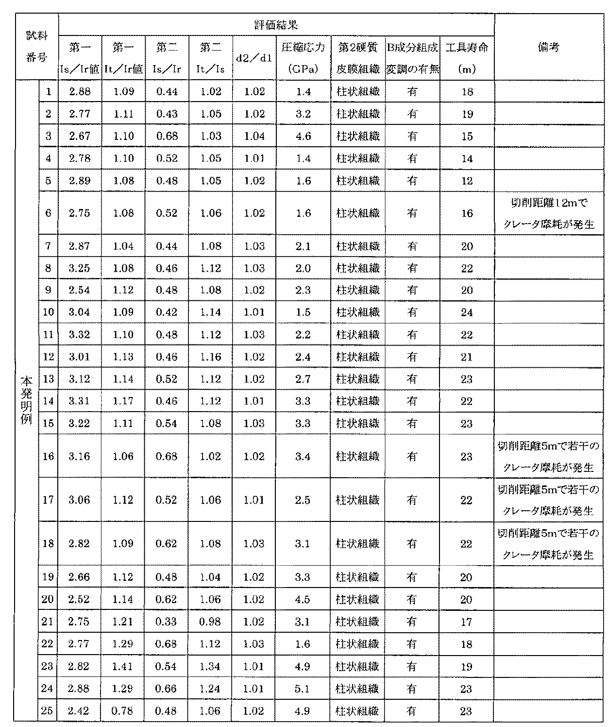
前記のようにして作製した各試料について、硬質皮膜組成を表1に、硬質皮膜の成膜条件を表2に、及び圧縮応力の測定値や被覆したインサートの切削試験の評価結果を表3に夫々示す。TEMによる皮膜断面観察の結果、本発明例1〜48における第2硬質皮膜は全て柱状組織を有し、この柱状組織の結晶粒は結晶粒成長方向に対してB成分に組成差を有する組成変調構造を有していることを確認した。 For each sample prepared as described above, the hard coating composition is shown in Table 1, the hard coating formation conditions are shown in Table 2, and the measured values of compressive stress and the evaluation results of the coated insert cutting test are shown in Table 3. Each one is shown. As a result of observation of the film cross-section by TEM, all of the second hard films in Invention Examples 1 to 48 have a columnar structure, and the crystal grains of this columnar structure have a compositional difference in the B component with respect to the crystal grain growth direction. It was confirmed to have a structure.
作製した旋削用インサートを刃先交換式バイトに取り付け、以下の条件で旋削加工試験を行い、耐摩耗性、耐欠損性、密着性の優劣を確認した。切削評価に使用したインサートは、汎用的なCNMG120408形状を用い、超硬合金を基体として、JIS規格におけるM20種相当でHRA91を使用した。旋削加工を行うに当たり、チップブレーカ付き、すくい角が1度の特殊形状のインサートを使用した。評価方法は、切削距離5m時に発生する硬質皮膜被覆インサートの逃げ面、すくい面に発生する摩耗を、光学顕微鏡で50倍に拡大して観察した。更に切削を継続し、10μm以上の微小チッピングを含む欠損が発生した時点、または欠損がない場合は、逃げ面摩耗幅のVBmax値が0.3mmに到達した時点を工具寿命とし、この時の切削距離(m)によって性能を評価した。切削途中の刃先の損傷状態は、適宜観察を行った。 The produced turning insert was attached to a blade-type replaceable cutting tool, and a turning test was performed under the following conditions to confirm superiority or inferiority of wear resistance, fracture resistance, and adhesion. The insert used for the cutting evaluation uses a general-purpose CNMG120408 shape, using cemented carbide as a base, and HRA91 corresponding to M20 type in the JIS standard. In turning, a special insert with a chip breaker and a rake angle of 1 degree was used. In the evaluation method, the abrasion generated on the flank and rake face of the hard film-coated insert generated at a cutting distance of 5 m was observed with an optical microscope at a magnification of 50 times. Further, the cutting is continued, and when there is a defect including minute chipping of 10 μm or more, or when there is no defect, the time when the VBmax value of the flank wear width reaches 0.3 mm is defined as the tool life. Performance was evaluated by distance (m). The damage state of the cutting edge during cutting was appropriately observed.
(切削試験条件)
切削方法:長手方向連続切削
被削材形状:直径160mm、長さ600mmの丸棒材
被削材:S53C、HB260、調質材
軸方向切込み量:2.0mm
切削速度:300m/分
1回転あたりの送り量:0.4mm/回転
切削油:なし(Cutting test conditions)
Cutting method: Continuous cutting in the longitudinal direction Work material shape: Round bar material with a diameter of 160 mm and a length of 600 mm Work material: S53C, HB260, tempered material Axial depth of cut: 2.0 mm
Cutting speed: 300 m / min Feed rate per rotation: 0.4 mm / rotation Cutting oil: None
本発明例1〜5、比較例49、50は、硬質皮膜の膜厚の影響を見るために作製した。膜厚は被覆時間により調節した。第1硬質皮膜と第2硬質皮膜の膜厚比は1:1として同じとし、全体の膜厚のみを変化させた。硬質皮膜の膜厚が厚くなると圧縮応力は増大する傾向にあった。本発明例1〜5に示す総膜厚が5μm以上を有するものは、逃げ面摩耗、クレータ摩耗などの耐摩耗性に優れた。いずれの試料についても、切削初期5mにおける被加工物成分の刃先への溶着の発生はなかった。これは、本発明で規定する第2硬質皮膜を有することが、クレータ摩耗、耐溶着性に対し、大きな効果を持つものと考えられる。
本発明例1の総膜厚は10μm、圧縮応力値は1.4GPaであり、工具寿命は18mという満足のいく結果を得た。切削距離5m時の刃先の損傷状態を確認した結果、逃げ面摩耗量は0.068mmとなり、薄い膜厚の本発明例4、5よりも耐摩耗性に優れ、更に比較例40に比して格段に優れていた。切削途中の刃先の損傷状態を確認した所、切刃近傍における硬質皮膜の脱落、剥離、チッピング等は観察されず、正常摩耗を呈していた。パルス化されたバイアス電圧を印加して成膜を行った本発明例は、工具寿命が長く優れた結果であった。Invention Examples 1 to 5 and Comparative Examples 49 and 50 were prepared in order to see the influence of the film thickness of the hard coating. The film thickness was adjusted by the coating time. The film thickness ratio of the first hard film and the second hard film was the same as 1: 1, and only the entire film thickness was changed. The compressive stress tended to increase as the thickness of the hard coating increased. Those having a total film thickness of 5 μm or more shown in Invention Examples 1 to 5 were excellent in wear resistance such as flank wear and crater wear. In any of the samples, there was no occurrence of welding of the workpiece component to the cutting edge in the initial 5 m of cutting. It is considered that having the second hard film specified in the present invention has a great effect on crater wear and welding resistance.
In Example 1 of the present invention, the total film thickness was 10 μm, the compressive stress value was 1.4 GPa, and the tool life was 18 m. As a result of confirming the damaged state of the cutting edge when the cutting distance is 5 m, the flank wear amount is 0.068 mm, which is superior to the thin film thickness examples 4 and 5 of the present invention and further compared to the comparative example 40. It was much better. When the damaged state of the cutting edge was confirmed during cutting, the hard coating was not dropped, peeled off, chipped, or the like in the vicinity of the cutting edge, and normal wear was exhibited. The example of the present invention in which film formation was performed by applying a pulsed bias voltage had a long tool life and excellent results.
比較例49の総膜厚は40μmであり、圧縮応力は7.1GPaであり、本発明例1〜5に対して、工具寿命が劣った。
比較例39は、切削前に刃先エッジ部で微細な皮膜破壊が観察された。切削途中の刃先エッジ部の損傷状態を確認したところ、皮膜破壊が9μmの幅に拡大しており、この破壊部分から欠損に至った。総膜厚が40μmという厚膜化により圧縮応力が増大したためである。
比較例50の総膜厚は4μmであり、1.3GPaと低い圧縮応力を有していた。しかし、アブレッシブ摩耗が劣ったため工具寿命は短かった。The total film thickness of Comparative Example 49 was 40 μm, the compressive stress was 7.1 GPa, and the tool life was inferior to Invention Examples 1-5.
In Comparative Example 39, fine film breakage was observed at the edge of the blade edge before cutting. When the damage state of the edge part of the cutting edge during the cutting was confirmed, the film breakage expanded to a width of 9 μm, and the breakage part led to a defect. This is because the compressive stress is increased by increasing the total film thickness to 40 μm.
The total film thickness of Comparative Example 50 was 4 μm and had a low compressive stress of 1.3 GPa. However, the tool life was short due to inferior abrasive wear.
本発明例6、7は、第1硬質皮膜、第2硬質皮膜の膜厚比の影響を見るために作製した。本発明例6に示すように、第1硬質皮膜を厚くすることによって、本発明例1に比して工具寿命が優れた。これは、逃げ面摩耗の進行が抑制されたためと考えられた。しかし、本発明例6、7は、第2硬質皮膜が夫々1μm、3μmと薄く、切削途中でクレータ摩耗が発生した。クレータ摩耗の進行によって刃先強度が失われ、欠損に至った。再現性確認のために、総膜厚を12μmとし、第2硬質皮膜を0.3μmに被覆したものについても切削評価を行ったが、逃げ面摩耗の進行は抑制されるものの、クレータ摩耗が主体に進行し、寿命に至った。 Invention Examples 6 and 7 were prepared in order to observe the influence of the film thickness ratio of the first hard film and the second hard film. As shown in Inventive Example 6, the tool life was superior to Inventive Example 1 by increasing the thickness of the first hard coating. This was considered to be because progress of flank wear was suppressed. However, in Invention Examples 6 and 7, the second hard film was as thin as 1 μm and 3 μm, respectively, and crater wear occurred during cutting. The blade edge strength was lost due to the progress of crater wear, leading to defects. In order to confirm reproducibility, cutting evaluation was also performed for a film having a total film thickness of 12 μm and a second hard film coated to 0.3 μm, but the progress of flank wear was suppressed, but crater wear was the main component. Progressed to life.
本発明例8〜20、比較例51、52は、第1硬質皮膜の組成の影響を見るために作製した。被覆用ターゲット材組成を変化させて作製した。
工具寿命の最も優れた本発明例10は、タングステン(W)を10%含有し、本発明例1に比して、約1.3倍優れた。切削距離5m時の刃先状態を確認した所、刃先エッジ部においてチッピングは確認されず、逃げ面摩耗が0.029mmであった。切削部位における被加工物の溶着もほとんど発生しておらず、正常摩耗の進行のみで寿命に至った。逃げ面摩耗が優れた理由は、Wを含有させることによって、高硬度化したことであると考えられる。本発明例1における第1硬質皮膜の硬度が28GPa、本発明例10が32GPaであった。更に、耐酸化性が高まったため、逃げ面摩耗進行が抑制されたと考えられる。特に、耐酸化性が高まると、最も切削熱が高くなる工具境界部における損傷が低減される傾向にあった。また、溶着が発生しなかった理由は、最外皮膜の第2硬質皮膜に硼素(B)を含有し、潤滑特性が優れたためである。
本発明例12はニオブ(Nb)を10%含有し、本発明例13、14はクロム(Cr)、シリコン(Si)を含有したため、第1硬質皮膜の機械的特性が高まり、本発明例1に比して優れた。
本発明例15に示すように、第1硬質皮膜にBを含有させても工具寿命は優れた。第2硬質皮膜が摩耗した後に露出する第1硬質皮膜の部分でも溶着が抑制された。第1硬質皮膜中にBを含有させても、溶着やクレータ摩耗に対し、格段な効果が得られた。
本発明例8〜20は、第1硬質皮膜がAlと4a、5a、6a族元素、Si、Bから選択された元素の窒化物であるため、耐熱性、硬度が格段に高められた。Invention Examples 8 to 20 and Comparative Examples 51 and 52 were prepared in order to observe the influence of the composition of the first hard coating. It was produced by changing the composition of the target material for coating.
Invention Example 10, which has the best tool life, contained 10% tungsten (W), and was about 1.3 times better than Invention Example 1. When the cutting edge state was confirmed when the cutting distance was 5 m, chipping was not confirmed at the cutting edge part, and the flank wear was 0.029 mm. There was almost no welding of the workpiece at the cutting site, and the life was reached only by the progress of normal wear. It is considered that the reason why the flank wear is excellent is that the hardness is increased by containing W. The hardness of the first hard coating in Invention Example 1 was 28 GPa, and Invention Example 10 was 32 GPa. Furthermore, since the oxidation resistance has increased, it is considered that the progress of flank wear was suppressed. In particular, when the oxidation resistance is increased, damage at the tool boundary where the cutting heat is highest tends to be reduced. Further, the reason why welding did not occur is that boron (B) was contained in the second hard film of the outermost film and the lubrication characteristics were excellent.
Invention Example 12 contains 10% of niobium (Nb), and Invention Examples 13 and 14 contain chromium (Cr) and silicon (Si), so that the mechanical properties of the first hard coating are enhanced, and Invention Example 1 Excellent compared to
As shown in Invention Example 15, the tool life was excellent even when B was contained in the first hard coating. Welding was also suppressed at the portion of the first hard film exposed after the second hard film was worn. Even when B was contained in the first hard film, a remarkable effect was obtained with respect to welding and crater wear.
In Invention Examples 8 to 20, since the first hard film is a nitride of an element selected from Al, Group 4a, 5a, and 6a elements, Si, and B, heat resistance and hardness are remarkably improved.
比較例51は、第1硬質皮膜のAl含有量が75%であり、切削初期から溶着現象や、工具逃げ面のアブレッシブ摩耗が進行した。第1硬質皮膜断面の組織観察では、組織は微細化していた。このため、圧縮応力が増大し密着性の劣化が考えられる。また、第1硬質皮膜の硬度は20GPaとなり、硬度低下が摩耗の早期進行をもたらした。
比較例41についてX線回折を行った結果、面心立方構造のピークの他に六方晶構造のピークが出現した。調査の結果、AlN化合物に起因するピークであることが確認された。これにより、耐摩耗性が著しく劣化したものと考えられる。比較例42も同様の現象が確認された。In Comparative Example 51, the Al content of the first hard coating was 75%, and the welding phenomenon and the abrasive wear of the tool flank progressed from the beginning of cutting. In the observation of the structure of the first hard film cross section, the structure was refined. For this reason, compressive stress increases and adhesion deterioration can be considered. Further, the hardness of the first hard film was 20 GPa, and the decrease in hardness caused early progress of wear.
As a result of performing X-ray diffraction on Comparative Example 41, a hexagonal structure peak appeared in addition to the face-centered cubic structure peak. As a result of the investigation, it was confirmed that the peak was attributed to the AlN compound. Thereby, it is considered that the wear resistance is remarkably deteriorated. In Comparative Example 42, the same phenomenon was confirmed.
本発明例21〜24、比較例53、54は、第2硬質皮膜の組成の影響を見るために作製した。被覆用ターゲット材の組成を変化させて作製した。本発明例21、22は、第2硬質皮膜のB含有量を夫々1%、25%とした。本発明例23のSi含有量は20%、本発明例24は、BとSiを含有させた。これらの第2硬質皮膜の断面の組織観察をした所、何れも柱状組織であることが確認された。
一方、第2硬質皮膜のB含有量が40%の比較例53、Si含有量が30%の比較例54について、第2硬質皮膜の断面組織を観察して、何れも微細化組織であることを確認した。B、Si含有量が多くなると、切削初期から硬質皮膜の剥離とクレータ摩耗が発生した。皮膜組織の差が切削性能の優劣をもたらした。特に、Siの含有量が30%の比較例44は、切削途中段階から、第2硬質皮膜の表面に溶着物が多く観察された。Invention Examples 21 to 24 and Comparative Examples 53 and 54 were prepared in order to see the influence of the composition of the second hard film. It was produced by changing the composition of the target material for coating. In inventive examples 21 and 22, the B content of the second hard coating was 1% and 25%, respectively. Inventive Example 23 had a Si content of 20%, and Inventive Example 24 contained B and Si. When the structures of the cross sections of these second hard coatings were observed, it was confirmed that all of them were columnar structures.
On the other hand, regarding the comparative example 53 in which the B content of the second hard film is 40% and the comparative example 54 in which the Si content is 30%, the cross-sectional structure of the second hard film is observed, and both are fine structures. It was confirmed. When the B and Si contents were increased, peeling of the hard coating and crater wear occurred from the beginning of cutting. The difference in the film structure resulted in superiority or inferior cutting performance. In particular, in Comparative Example 44 in which the Si content was 30%, many deposits were observed on the surface of the second hard film from the middle of cutting.
本発明例25、26、比較例55、56は、第1硬質皮膜に含有される酸素、炭素の影響を見るために作製した。酸素、炭化水素系ガスを反応ガスの一部として用いた。酸素を含有させた本発明例26と比較例56については、成膜時に窒素、アルゴン(Ar)、酸素を同時に導入した。いずれも全圧を3.5Paとし、本発明例26の場合は、窒素88体積%アルゴン10体積%:酸素2体積%のガス流量比率で導入した。これは酸素を多く導入したときに、成膜時に発生させるアーク放電が不安定になったため、不活性ガスのArを導入して、全圧を調整した。Arガスを使用しなくても放電は可能であるが、より安定化を図るためにArガスを導入した。比較例56は、酸素含有量を増やすために、窒素量を減らし、Arガス、酸素ガス量を増やして作製した。
本発明例25、26の工具寿命は、酸素元素、炭素元素を含有しない本発明例1に比して1.2倍程度優れた。また、切削距離5m時の刃先の損傷状態は、本発明例1に比して溶着、逃げ面摩耗が少ない傾向にあった。更に、すくい面のクレータ摩耗の発生も低減されていた。クレータ摩耗は、切削温度上昇に伴う化学反応によって発生することより、酸素、炭素を含有させることによって潤滑特性が高まり摩擦係数が低減される。その結果、すくい面を切屑が擦過する際の切削温度が抑制され、摩耗が低減したと考えられる。Invention Examples 25 and 26 and Comparative Examples 55 and 56 were prepared in order to observe the influence of oxygen and carbon contained in the first hard film. Oxygen and hydrocarbon gas were used as part of the reaction gas. For Invention Example 26 and Comparative Example 56 containing oxygen, nitrogen, argon (Ar), and oxygen were simultaneously introduced during film formation. In all cases, the total pressure was 3.5 Pa, and in the case of Invention Example 26, the gas was introduced at a gas flow rate ratio of 88% by volume of nitrogen, 10% by volume of argon, and 2% by volume of oxygen. In this case, when a large amount of oxygen was introduced, the arc discharge generated during film formation became unstable. Therefore, the inert gas Ar was introduced to adjust the total pressure. Although discharge is possible without using Ar gas, Ar gas was introduced for further stabilization. In Comparative Example 56, in order to increase the oxygen content, the amount of nitrogen was reduced and the amounts of Ar gas and oxygen gas were increased.
The tool life of Inventive Examples 25 and 26 was about 1.2 times better than Inventive Example 1 that did not contain oxygen and carbon elements. Moreover, the damage state of the blade edge at the time of the cutting distance of 5 m tended to be less welded and flank wear than the first example of the present invention. Furthermore, the occurrence of crater wear on the rake face was reduced. Since crater wear occurs due to a chemical reaction accompanying an increase in cutting temperature, the inclusion of oxygen and carbon increases the lubrication characteristics and reduces the friction coefficient. As a result, it is considered that the cutting temperature at which the chips scrape the rake face is suppressed, and wear is reduced.
比較例55、56は、第1硬質皮膜のx値、y値が10%以上であったため、切削初期から硬質皮膜の剥離とクレータ摩耗発生が確認され、同様に第1硬質皮膜断面の組織観察をした結果、微細化していた。炭素を含有しない本発明例1、炭素含有量が7%の本発明例25、15%の比較例55について、第1硬質皮膜のみの試料を作製し摩擦係数測定を行った。この摩擦係数測定は、ボールオンディスク方式で行い、コーティングした超硬合金製ディスクにSUJ2のφ6mmボールを摺動させ、大気中、無潤滑で測定した。測定温度600℃における、硬質皮膜の耐摩耗性、ならびに耐溶着性を調査した。本発明例1の摩擦係数は0.8、本発明例25は0.5、比較例55は0.8となった。第1硬質皮膜に炭素が多く含有しても、皮膜断面の組織が微細化すると、逃げ面摩耗、クレータ摩耗や被加工物の工具刃先への溶着といった損傷が切削初期から発生することが確認された。これは、酸素を含有させた場合も同様の傾向が観察された。 In Comparative Examples 55 and 56, since the x value and y value of the first hard film were 10% or more, peeling of the hard film and occurrence of crater wear were confirmed from the beginning of cutting, and the structure observation of the cross section of the first hard film was similarly performed. As a result, it was miniaturized. For Invention Example 1 containing no carbon, Invention Example 25 having a carbon content of 7%, and Comparative Example 55 having a carbon content of 15%, a sample of only the first hard film was prepared and the coefficient of friction was measured. The coefficient of friction was measured by a ball-on-disk method, and a SUJ2 φ6 mm ball was slid on a coated cemented carbide disc and measured without lubrication in the atmosphere. The wear resistance and welding resistance of the hard film at a measurement temperature of 600 ° C. were investigated. The friction coefficient of Invention Example 1 was 0.8, Invention Example 25 was 0.5, and Comparative Example 55 was 0.8. Even if the first hard coating contains a large amount of carbon, it is confirmed that damage such as flank wear, crater wear, and welding of the workpiece to the tool edge occurs from the beginning of cutting if the microstructure of the cross section of the coating becomes finer. It was. The same tendency was observed when oxygen was contained.
本発明例27〜32、比較例57、58は、成膜時における反応圧力の組成への影響を見るために作製した。特にe/f値、m/p値による圧縮応力への影響を調査した。この時、反応圧力を変化させ、0.2Pa〜13.5Paの範囲に設定した。反応圧力が2.2〜9.1Paで成膜を行った本発明例1、27〜32の場合、本発明例1に比して第1硬質皮膜成膜時の反応圧力が高圧力側で工具寿命が優れた。本発明例1に比して、同じく低圧力側である本発明例29は、比較例57、58に比して格段に工具寿命が優れたが、切削初期に極微小なチッピングが発生していた。特にe/f値が1.16の本発明例27が最も優れ、第1硬質皮膜のチッピングなど、不安定要素は発生しなかった。反応圧力が最も低い1.6Paで成膜を行った比較例57は、圧縮応力が6.9GPaであり、e/f値は0.82、工具寿命は8mとなった。これは本発明例1に比して約60%の短寿命であった。窒素圧力が低い程、圧縮応力が増大し、e/f値は、低い値を示す傾向にあった。この理由は、第1硬質皮膜の圧縮応力が高いためと考えられる。圧縮応力が6.0GPaを超える様になると、切削途中のインサート刃先損傷状態観察において、刃先エッジ部における第1硬質皮膜の破壊が確認された。再現性を確認するため、比較例57のインサートの新しいコーナーを用いて、数度の切削評価を行った結果、工具寿命は、2m、0.2mとばらつき、安定しなかった。 Invention Examples 27 to 32 and Comparative Examples 57 and 58 were prepared in order to observe the influence of the reaction pressure on the composition during film formation. In particular, the influence of the e / f value and m / p value on the compressive stress was investigated. At this time, the reaction pressure was changed and set in the range of 0.2 Pa to 13.5 Pa. In the present invention examples 1 and 27 to 32 in which the film was formed at a reaction pressure of 2.2 to 9.1 Pa, the reaction pressure at the time of forming the first hard film was higher than that of the first example of the present invention. Excellent tool life. Inventive Example 29, which is also on the low pressure side as compared with Inventive Example 1, has a far superior tool life as compared with Comparative Examples 57 and 58, but extremely small chipping occurred at the beginning of cutting. It was. In particular, Invention Example 27 having an e / f value of 1.16 was the most excellent, and unstable elements such as chipping of the first hard coating did not occur. In Comparative Example 57 in which the film was formed at the lowest reaction pressure of 1.6 Pa, the compressive stress was 6.9 GPa, the e / f value was 0.82, and the tool life was 8 m. This was a short life of about 60% compared to Example 1 of the present invention. The lower the nitrogen pressure, the greater the compressive stress and the lower the e / f value. This reason is considered to be because the compressive stress of the first hard coating is high. When the compressive stress exceeded 6.0 GPa, it was confirmed that the first hard coating was broken at the edge of the blade edge in the damage state of the insert blade edge during cutting. In order to confirm reproducibility, as a result of performing cutting evaluation of several degrees using a new corner of the insert of Comparative Example 57, the tool life varied from 2 m to 0.2 m and was not stable.
比較例58の反応圧力13.5Pa時にm/p値は1.28となり、そのときの圧縮応力が7GPaを超え、切削初期に皮膜剥離が発生し、早期欠損に至った。切削距離5m時の刃先の損傷状態を観察できなかったため、新しいコーナーを用いて、更に、初期の切削距離1mでの損傷を確認した結果、刃先エッジ部における基体と第1硬質皮膜界面からの膜剥離と、第1硬質皮膜が脱落した部位において多量の溶着が発生していた。また、逃げ面の大きな摩耗、クレータ摩耗が発生していた。これは、第1硬質皮膜の硬度の低下が原因であると考えられた。e/f値は1.32、m/p値は1.28を示し、第1硬質皮膜の断面組織において柱状組織を有するものの、第1、第2硬質皮膜中に欠陥が多く発生し、密着性や耐摩耗性が劣った。この理由は、反応圧力を13.5Paで行ったことにより、イオンが基体に入射する際の運動エネルギーが低くなったためであると考えられる。 When the reaction pressure of Comparative Example 58 was 13.5 Pa, the m / p value was 1.28, the compressive stress at that time exceeded 7 GPa, and film peeling occurred at the beginning of cutting, leading to early chipping. Since the damage state of the cutting edge at the cutting distance of 5 m could not be observed, the damage at the initial cutting distance of 1 m was confirmed using a new corner, and as a result, the film from the substrate and the first hard coating interface at the edge of the cutting edge A large amount of welding occurred at the site where peeling and the first hard coating were removed. In addition, large wear on the flank and crater wear occurred. This was thought to be due to a decrease in the hardness of the first hard coating. The e / f value is 1.32 and the m / p value is 1.28. Although the cross-sectional structure of the first hard film has a columnar structure, many defects occur in the first and second hard films, and the adhesion Inferior in wear and wear resistance. The reason for this is considered to be that the kinetic energy when ions are incident on the substrate is lowered by performing the reaction pressure at 13.5 Pa.
本発明例33〜40、比較例59、60は、Is/Ir値の影響を見るために作製した。成膜時、パルスバイアスのパルス周波数を10kHzに一定とし、バイアス電圧値を変化させ、20〜300Vの範囲に設定した。本発明例1、本発明例33〜40は、Is/Ir値が本発明の規定範囲内であり、圧縮応力も4GPa以下となり、工具寿命が優れた。また、バイアス電圧を変化させた場合、Is/Ir値が変化し、それに伴い圧縮応力も変化した。比較例59、60は、圧縮応力が8GPaを超え、切削初期から硬質皮膜の膜剥離が観察された。圧縮応力が大きくなると、工具寿命が劣る結果となった。 Invention Examples 33 to 40 and Comparative Examples 59 and 60 were prepared in order to observe the influence of the Is / Ir value. At the time of film formation, the pulse frequency of the pulse bias was kept constant at 10 kHz, and the bias voltage value was changed and set in the range of 20 to 300V. In Invention Example 1 and Invention Examples 33 to 40, the Is / Ir value was within the specified range of the present invention, the compressive stress was 4 GPa or less, and the tool life was excellent. Further, when the bias voltage was changed, the Is / Ir value was changed, and the compressive stress was changed accordingly. In Comparative Examples 59 and 60, the compressive stress exceeded 8 GPa, and peeling of the hard film was observed from the beginning of cutting. When the compressive stress was increased, the tool life was inferior.
本発明例41〜46、比較例61〜63は、第1硬質皮膜のIt/Ir値の圧縮応力への影響を見るために作製した。この時、パルスバイアス電圧の正バイアス値を5〜40Vまで変化させた。正のバイアス電圧が大きくなると、相対的に(200)面への配向強度が強くなる傾向を示し、本発明例1、41〜46、比較例61〜63のIs/Ir値は、2.44〜4.46まで変化した。本発明例1、本発明例34〜36は、It/Ir値が本発明の規定範囲内であり、圧縮応力も比較的低くなり、満足のいく工具寿命が得られた。一方、比較例61〜63は正のバイアス電圧が20Vを超え、第1硬質皮膜のIt/Ir値は0.6を下回り、切削距離5m時の刃先損傷状態観察において、第1硬質皮膜の剥離が多く観察された。圧縮応力が高くなり6GPaを超えたため、基体と第1硬質皮膜界面からの剥離だけでなく、貝殻状の破壊も多く観察され、これが工具寿命低下をもたらした。第1硬質皮膜と第2硬質皮膜の界面の密着性を高めるためには、パルスバイアス電圧における正のバイアス電圧値を低く制御して、第1硬質皮膜の(111)面の配向強度を低くすることが重要である。負の値のみのバイアス電圧印加では、成膜時のマイクロアーキングなどにより発生する欠陥の抑制に不十分となるからである。 Invention Examples 41 to 46 and Comparative Examples 61 to 63 were prepared in order to see the effect of the It / Ir value of the first hard coating on the compressive stress. At this time, the positive bias value of the pulse bias voltage was changed from 5 to 40V. When the positive bias voltage increases, the orientation strength toward the (200) plane tends to be relatively strong, and the Is / Ir values of Invention Examples 1, 41 to 46 and Comparative Examples 61 to 63 are 2.44. It changed to ˜4.46. In Invention Example 1 and Invention Examples 34 to 36, the It / Ir value was within the specified range of the present invention, the compressive stress was relatively low, and a satisfactory tool life was obtained. On the other hand, in Comparative Examples 61 to 63, the positive bias voltage exceeded 20 V, the It / Ir value of the first hard coating was less than 0.6, and the first hard coating was peeled off when the blade edge was observed at a cutting distance of 5 m. Many were observed. Since the compressive stress increased and exceeded 6 GPa, not only peeling from the interface between the substrate and the first hard coating but also many shell-like fractures were observed, which resulted in a decrease in tool life. In order to improve the adhesion at the interface between the first hard film and the second hard film, the positive bias voltage value in the pulse bias voltage is controlled to be low, and the orientation strength of the (111) plane of the first hard film is lowered. This is very important. This is because application of a bias voltage having only a negative value is insufficient for suppressing defects caused by micro arcing during film formation.
本発明例47、48、比較例64、65は、第1硬質皮膜、第2硬質皮膜のX線回折における、それぞれ(200)面と(111)面の面間隔の影響を見るために作製した。面間隔はパルスバイアス電圧のパルス周波数を1〜40kHzの範囲で変化させることにより調節した。
本発明例47、48は、パルス周波数が夫々30kHz、2kHzの場合であるが、d2/d1値は1.01〜1.02を示し、硬質皮膜全体の圧縮応力が低くなり、第1硬質皮膜と第2硬質皮膜の密着性に優れ、満足のいく工具寿命が得られた。
一方、パルス周波数を1kHzで成膜を行った比較例64は、d2/d1値が1.07となり、第1硬質皮膜と第2硬質皮膜の面間隔のズレにより密着性が劣化した。比較例65は、切削初期に基体と硬質皮膜間の剥離よりも第1硬質皮膜と第2硬質皮膜の界面で剥離が多く観察された。これが短い工具寿命の原因であった。この理由は、40kHzで成膜を行ったためd2/d1値が0.99となり、硬質皮膜全体の圧縮応力が6.9GPaと増大して基体との密着性の他に、第1硬質皮膜と第2硬質皮膜の面間隔のミスフィットにより密着性が劣化したためである。
また、パルス周波数の変化によって第1硬質皮膜のIt/Ir値も変化することが確認された。パルス周波数と圧縮応力の関係には相関性があると考えられ、パルス周波数が大きくなると、圧縮応力は大きくなる傾向にあった。パルス周波数が大きくなると、直流バイアス電圧が印加される状態に近づくためと考えられる。Invention Examples 47 and 48 and Comparative Examples 64 and 65 were prepared in order to observe the influence of the (200) plane and (111) plane spacing on the X-ray diffraction of the first hard coating and the second hard coating, respectively. . The surface spacing was adjusted by changing the pulse frequency of the pulse bias voltage in the range of 1 to 40 kHz.
Examples 47 and 48 of the present invention are cases where the pulse frequency is 30 kHz and 2 kHz, respectively, but the d2 / d1 value is 1.01 to 1.02, and the compressive stress of the entire hard coating is reduced, and the first hard coating is reduced. And excellent adhesion of the second hard film, and a satisfactory tool life was obtained.
On the other hand, in Comparative Example 64 in which film formation was performed at a pulse frequency of 1 kHz, the d2 / d1 value was 1.07, and the adhesion deteriorated due to the gap between the first hard film and the second hard film. In Comparative Example 65, more peeling was observed at the interface between the first hard film and the second hard film than at the initial stage of cutting than between the base and the hard film. This was the cause of the short tool life. The reason for this is that since the film was formed at 40 kHz, the d2 / d1 value was 0.99, the compressive stress of the entire hard film increased to 6.9 GPa, and in addition to the adhesion to the substrate, the first hard film and the first hard film This is because the adhesiveness deteriorated due to misfit of the spacing between the two hard coatings.
It was also confirmed that the It / Ir value of the first hard coating also changed with the change of the pulse frequency. The relationship between the pulse frequency and the compressive stress is considered to be correlated, and the compressive stress tends to increase as the pulse frequency increases. This is considered to be due to the fact that the DC bias voltage is applied as the pulse frequency increases.
本発明の硬質皮膜被覆工具は、例えば、耐摩耗性が要求される金属加工用の工具全般等において適用することができる。 The hard film-coated tool of the present invention can be applied to, for example, general tools for metal processing that require wear resistance.
Claims (4)
該第1硬質皮膜の組成は、(AlaMe100−a)eNf(但し、aは原子%であり、e及びfは夫々原子比を表し、35≦a≦65、及び0.85≦e/f≦1.25であり、Alはアルミニウムであり、Meは4a、5a、6a族、Si及びBから選択される少なくとも1種の元素であり、Nは窒素である。)で表され、
該第2硬質皮膜の組成は、(Ti100−hBh)mNp(但し、hは原子%であり、m及びpは夫々原子比を表し、0<h≦30、及び0.90≦m/p≦1.15であり、Tiはチタニウムであり、Bは硼素であり、Nは窒素である。)で表され、
該第1硬質皮膜、及び該第2硬質皮膜の結晶構造は夫々面心立方構造であり、
(111)面のピーク強度をIr、(200)面のピーク強度をIs、及び(220)面のピーク強度をItとしたときに、該第1硬質皮膜のX線回折において1.5≦Is/Ir≦15.0、及び0.6≦It/Ir≦1.5であり、該第2硬質皮膜のX線回折において0.2≦Is/Ir≦1.0、及び0.6≦It/Is≦1.5であり、
該第1硬質皮膜と該第2硬質皮膜のX線回折において、該第1硬質皮膜の(200)面の面間隔(nm)をd1、該第2硬質皮膜の(111)面の面間隔(nm)をd2としたときに、1.00≦d2/d1≦1.03であり、
該第2硬質皮膜は柱状組織を有し、該柱状組織の結晶粒はB成分に組成差を有する組成変調構造を有することを特徴とする硬質皮膜被覆工具。In a hard film coating tool in which a hard film having a compressive stress is coated on a substrate with a thickness of 5 to 30 μm, the hard film is coated with the first hard film and the second hard film from the surface of the substrate. The outer film is coated with the second hard film,
The composition of the first hard coating is (Al a Me 100-a ) e N f (where a is atomic%, e and f represent atomic ratios, respectively 35 ≦ a ≦ 65, and 0.85) ≦ e / f ≦ 1.25, Al is aluminum, Me is at least one element selected from groups 4a, 5a, and 6a, Si and B, and N is nitrogen. And
The composition of the second hard coating is (Ti 100-h B h ) m N p (where h is atomic%, m and p represent atomic ratios, respectively, 0 <h ≦ 30, and 0.90) ≦ m / p ≦ 1.15, Ti is titanium, B is boron, and N is nitrogen.)
The crystal structures of the first hard film and the second hard film are face-centered cubic structures, respectively.
When the peak intensity of the (111) plane is Ir, the peak intensity of the (200) plane is Is, and the peak intensity of the (220) plane is It, 1.5 ≦ Is in the X-ray diffraction of the first hard film. /Ir≦15.0 and 0.6 ≦ It / Ir ≦ 1.5, and in the X-ray diffraction of the second hard film, 0.2 ≦ Is / Ir ≦ 1.0 and 0.6 ≦ It /Is≦1.5,
In the X-ray diffraction of the first hard coating and the second hard coating, the surface spacing (nm) of the (200) plane of the first hard coating is d1, and the (111) plane spacing of the second hard coating ( nm) is d2, and 1.00 ≦ d2 / d1 ≦ 1.03,
The hard film-coated tool, wherein the second hard film has a columnar structure, and the crystal grains of the columnar structure have a composition modulation structure having a composition difference in the B component.
Priority Applications (1)
| Application Number | Priority Date | Filing Date | Title |
|---|---|---|---|
| JP2009159274A JP5056808B2 (en) | 2009-06-15 | 2009-06-15 | Hard coating tool |
Applications Claiming Priority (1)
| Application Number | Priority Date | Filing Date | Title |
|---|---|---|---|
| JP2009159274A JP5056808B2 (en) | 2009-06-15 | 2009-06-15 | Hard coating tool |
Publications (2)
| Publication Number | Publication Date |
|---|---|
| JP2010284788A JP2010284788A (en) | 2010-12-24 |
| JP5056808B2 true JP5056808B2 (en) | 2012-10-24 |
Family
ID=43540892
Family Applications (1)
| Application Number | Title | Priority Date | Filing Date |
|---|---|---|---|
| JP2009159274A Active JP5056808B2 (en) | 2009-06-15 | 2009-06-15 | Hard coating tool |
Country Status (1)
| Country | Link |
|---|---|
| JP (1) | JP5056808B2 (en) |
Families Citing this family (2)
| Publication number | Priority date | Publication date | Assignee | Title |
|---|---|---|---|---|
| WO2016084939A1 (en) * | 2014-11-27 | 2016-06-02 | 三菱マテリアル株式会社 | Surface-coated cutting tool with excellent chipping resistance and wear resistance |
| JP6634647B2 (en) | 2014-11-27 | 2020-01-22 | 三菱マテリアル株式会社 | Surface coated cutting tool with excellent chipping and wear resistance |
Family Cites Families (10)
| Publication number | Priority date | Publication date | Assignee | Title |
|---|---|---|---|---|
| JP3003986B2 (en) * | 1996-05-21 | 2000-01-31 | 日立ツール株式会社 | Surface-coated insert made of cemented carbide |
| JP3838796B2 (en) * | 1998-10-23 | 2006-10-25 | 株式会社荏原製作所 | Hard film for sliding members |
| JP4616213B2 (en) * | 2001-06-19 | 2011-01-19 | 株式会社神戸製鋼所 | Hard coating for cutting tools |
| JP3616049B2 (en) * | 2001-11-07 | 2005-02-02 | 日立ツール株式会社 | Physical vapor deposition hard coating tool with excellent crater wear resistance |
| JP2004042149A (en) * | 2002-07-09 | 2004-02-12 | Hitachi Tool Engineering Ltd | Coated cutting tool |
| JP3679076B2 (en) * | 2002-09-18 | 2005-08-03 | 日立ツール株式会社 | Hard coating tool |
| JP3779949B2 (en) * | 2002-10-16 | 2006-05-31 | 日立ツール株式会社 | Hard coating tool |
| JP2004314182A (en) * | 2003-02-25 | 2004-11-11 | Hitachi Tool Engineering Ltd | Coated drill |
| JP4958134B2 (en) * | 2003-12-18 | 2012-06-20 | 日立ツール株式会社 | Hard coating tool |
| JP4808972B2 (en) * | 2005-01-27 | 2011-11-02 | 京セラ株式会社 | Surface coated cutting tool |
-
2009
- 2009-06-15 JP JP2009159274A patent/JP5056808B2/en active Active
Also Published As
| Publication number | Publication date |
|---|---|
| JP2010284788A (en) | 2010-12-24 |
Similar Documents
| Publication | Publication Date | Title |
|---|---|---|
| JP5246165B2 (en) | Method for producing hard coating member | |
| JP5303816B2 (en) | Hard coating tool | |
| KR100937072B1 (en) | Hard coating having excellent wear resistance and oxidation resistance, the target for forming the hard coating, and hard coating having excellent high temperature lubrication and wear resistance, and target for forming the hard coating | |
| US9180522B2 (en) | Coated cutting tool insert | |
| JP3934136B2 (en) | Hard film coating member and coating method thereof | |
| CN100525968C (en) | Thin wear resistant coating | |
| JP5321975B2 (en) | Surface coated cutting tool | |
| JP4388582B2 (en) | Hard coating layer and method for forming the same | |
| KR102167200B1 (en) | Cloth cutting tool | |
| JP2012045650A (en) | Hard film-coated cutting tool | |
| KR101079902B1 (en) | Surface-coated cutting tool | |
| KR20240026951A (en) | cutting tools | |
| JP2008075178A (en) | Thick coating film-coated member and thick coating film-coated member production method | |
| JP5098657B2 (en) | Hard coating coated member | |
| JP2010284787A (en) | Hard film coated cutting tool | |
| JP7853789B2 (en) | Coating tools for machining difficult-to-process materials | |
| KR101170396B1 (en) | Hard coating and its production method | |
| JP5056808B2 (en) | Hard coating tool | |
| JP4970886B2 (en) | Surface coated cutting tool | |
| JP2011189499A (en) | Hard film coated tool | |
| JP2010120100A (en) | Hard coating film coated tool for turning | |
| JP5305236B2 (en) | Hard coating tool | |
| JP2011167838A (en) | Hard-film coated cutting tool | |
| JP2006225703A (en) | Hard film, stacked type hard film and method for producing the same | |
| JP2006192543A (en) | Surface-coated cutting tool and manufacturing method thereof |
Legal Events
| Date | Code | Title | Description |
|---|---|---|---|
| A977 | Report on retrieval |
Free format text: JAPANESE INTERMEDIATE CODE: A971007 Effective date: 20120619 |
|
| TRDD | Decision of grant or rejection written | ||
| A01 | Written decision to grant a patent or to grant a registration (utility model) |
Free format text: JAPANESE INTERMEDIATE CODE: A01 Effective date: 20120703 |
|
| A01 | Written decision to grant a patent or to grant a registration (utility model) |
Free format text: JAPANESE INTERMEDIATE CODE: A01 |
|
| A61 | First payment of annual fees (during grant procedure) |
Free format text: JAPANESE INTERMEDIATE CODE: A61 Effective date: 20120716 |
|
| FPAY | Renewal fee payment (event date is renewal date of database) |
Free format text: PAYMENT UNTIL: 20150810 Year of fee payment: 3 |
|
| R150 | Certificate of patent or registration of utility model |
Ref document number: 5056808 Country of ref document: JP Free format text: JAPANESE INTERMEDIATE CODE: R150 Free format text: JAPANESE INTERMEDIATE CODE: R150 |
|
| S531 | Written request for registration of change of domicile |
Free format text: JAPANESE INTERMEDIATE CODE: R313531 |
|
| S533 | Written request for registration of change of name |
Free format text: JAPANESE INTERMEDIATE CODE: R313533 |
|
| R350 | Written notification of registration of transfer |
Free format text: JAPANESE INTERMEDIATE CODE: R350 |
|
| S533 | Written request for registration of change of name |
Free format text: JAPANESE INTERMEDIATE CODE: R313533 |
|
| R350 | Written notification of registration of transfer |
Free format text: JAPANESE INTERMEDIATE CODE: R350 |