JP5111102B2 - Fine movement mechanism for scanning probe microscope and scanning probe microscope using the same - Google Patents
Fine movement mechanism for scanning probe microscope and scanning probe microscope using the same Download PDFInfo
- Publication number
- JP5111102B2 JP5111102B2 JP2007504663A JP2007504663A JP5111102B2 JP 5111102 B2 JP5111102 B2 JP 5111102B2 JP 2007504663 A JP2007504663 A JP 2007504663A JP 2007504663 A JP2007504663 A JP 2007504663A JP 5111102 B2 JP5111102 B2 JP 5111102B2
- Authority
- JP
- Japan
- Prior art keywords
- fine movement
- movement mechanism
- probe
- probe microscope
- stage
- Prior art date
- Legal status (The legal status is an assumption and is not a legal conclusion. Google has not performed a legal analysis and makes no representation as to the accuracy of the status listed.)
- Expired - Fee Related
Links
Images


Classifications
-
- G—PHYSICS
- G01—MEASURING; TESTING
- G01Q—SCANNING-PROBE TECHNIQUES OR APPARATUS; APPLICATIONS OF SCANNING-PROBE TECHNIQUES, e.g. SCANNING PROBE MICROSCOPY [SPM]
- G01Q10/00—Scanning or positioning arrangements, i.e. arrangements for actively controlling the movement or position of the probe
- G01Q10/04—Fine scanning or positioning
-
- B—PERFORMING OPERATIONS; TRANSPORTING
- B82—NANOTECHNOLOGY
- B82Y—SPECIFIC USES OR APPLICATIONS OF NANOSTRUCTURES; MEASUREMENT OR ANALYSIS OF NANOSTRUCTURES; MANUFACTURE OR TREATMENT OF NANOSTRUCTURES
- B82Y35/00—Methods or apparatus for measurement or analysis of nanostructures
-
- G—PHYSICS
- G01—MEASURING; TESTING
- G01Q—SCANNING-PROBE TECHNIQUES OR APPARATUS; APPLICATIONS OF SCANNING-PROBE TECHNIQUES, e.g. SCANNING PROBE MICROSCOPY [SPM]
- G01Q30/00—Auxiliary means serving to assist or improve the scanning probe techniques or apparatus, e.g. display or data processing devices
- G01Q30/02—Non-SPM analysing devices, e.g. SEM [Scanning Electron Microscope], spectrometer or optical microscope
- G01Q30/025—Optical microscopes coupled with SPM
Landscapes
- Physics & Mathematics (AREA)
- Health & Medical Sciences (AREA)
- General Health & Medical Sciences (AREA)
- General Physics & Mathematics (AREA)
- Nuclear Medicine, Radiotherapy & Molecular Imaging (AREA)
- Radiology & Medical Imaging (AREA)
- Chemical & Material Sciences (AREA)
- Engineering & Computer Science (AREA)
- Nanotechnology (AREA)
- Analytical Chemistry (AREA)
- Crystallography & Structural Chemistry (AREA)
- Length Measuring Devices With Unspecified Measuring Means (AREA)
Description
本発明は、試料の表面にプローブを近接または接触させて走査することにより、試料の表面形状や粘弾性等の各種の物性情報を測定する走査型プローブ顕微鏡に設けられる走査型プローブ顕微鏡用微動機構およびこれを有する走査型プローブ顕微鏡に関するものである。 The present invention relates to a fine-motion mechanism for a scanning probe microscope provided in a scanning probe microscope that measures various physical property information such as the surface shape and viscoelasticity of a sample by scanning the probe in the vicinity of or in contact with the surface of the sample. And a scanning probe microscope having the same.
周知のように、金属、半導体、セラミック、樹脂、高分子、生体材料、絶縁物等の試料を微小領域にて測定し、試料の粘弾性等の物性情報や試料の表面形状の観察等を行う装置として、走査型プローブ顕微鏡(SPM:Scanning Probe Microscope)が知られている。 As is well known, samples of metals, semiconductors, ceramics, resins, polymers, biomaterials, insulators, etc. are measured in a minute region, and physical property information such as viscoelasticity of the sample and observation of the surface shape of the sample are performed. As an apparatus, a scanning probe microscope (SPM) is known.
これら走査型プローブ顕微鏡の中には、試料が載置されるステージと、先端にプローブを有し、試料の表面に近接または接触させるカンチレバーとを備えたものが周知となっている(例えば、特許文献1参照。)。そして、これらステージとプローブとをX、Y方向に相対的に移動させて、プローブにより試料を走査させるようになっており、この走査中にカンチレバーの変位量を測定しながら、ステージまたはプローブをZ方向に動作させて、試料とプローブの距離制御を行うことにより、各種物性情報を測定するようになっている。 Among these scanning probe microscopes, those having a stage on which a sample is placed and a cantilever having a probe at the tip and approaching or contacting the surface of the sample are well known (for example, patents). Reference 1). The stage and the probe are moved relative to each other in the X and Y directions, and the sample is scanned by the probe. While measuring the displacement amount of the cantilever during the scanning, the stage or the probe is moved to the Z direction. By operating in the direction and controlling the distance between the sample and the probe, various physical property information is measured.
ところで、測定精度を向上させるためには、走査のためのステージおよびプローブの移動を高精度に行う必要がある。そのため、ステージおよびプローブを精度良く移動させるために、走査型プローブ顕微鏡用微動機構が設けられているのが一般的である。 Incidentally, in order to improve the measurement accuracy, it is necessary to move the stage and the probe for scanning with high accuracy. For this reason, in order to move the stage and the probe with high accuracy, a scanning probe microscope fine movement mechanism is generally provided.
走査型プローブ顕微鏡用微動機構は、ステージおよびプローブを微動させるための3次元アクチュエータなどの駆動部を備えており、この3次元アクチュエータによりX、Y、Z方向に移動させるものが周知となっている。 The fine movement mechanism for a scanning probe microscope includes a drive unit such as a three-dimensional actuator for finely moving the stage and the probe, and a mechanism that moves in the X, Y, and Z directions by this three-dimensional actuator is well known. .
ここで、プローブによる走査スピードを向上させるためには、X、Y方向の移動に比して、Z方向の移動について段違いの高速性が要求される。なぜなら、Z方向については、XY方向に走査中に、試料とプローブの距離が一定となるように、随時追従させる必要があるからである。
しかしながら、上記のように3次元アクチュエータを用いた構成では、その3次元アクチュエータによって、Z方向だけでなくX、Y方向にも動かす必要があるため、3次元アクチュエータ自体が大きくなってしまい、これにより3次元アクチュエータの共振周波数が低下してしまう。そのため、Z方向の振動の周波数を上げるのが困難になるという問題がある。また、3次元アクチュエータによってXYZ方向に同時に動かすため、それらが互いに影響し合い、移動精度が低下してしまう。 However, in the configuration using the three-dimensional actuator as described above, the three-dimensional actuator itself needs to be moved not only in the Z direction but also in the X and Y directions. The resonance frequency of the three-dimensional actuator is lowered. Therefore, there is a problem that it is difficult to increase the frequency of vibration in the Z direction. Further, since the three-dimensional actuators are simultaneously moved in the XYZ directions, they affect each other, and the movement accuracy is lowered.
本発明は、このような事情に鑑みてなされたものであって、プローブによる走査スピードをより一層向上させつつ、高精度に測定することができる走査型プローブ顕微鏡用微動機構およびこれを含む走査型プローブ顕微鏡を提供することを目的とする。 The present invention has been made in view of such circumstances, and a fine movement mechanism for a scanning probe microscope capable of measuring with high accuracy while further improving the scanning speed of the probe, and a scanning type including the same An object is to provide a probe microscope.
上記課題を解決するために、本発明は以下の手段を提供する。 In order to solve the above problems, the present invention provides the following means.
本発明は、試料が載置されるステージと、このステージに載置された前記試料の表面に近接または接触させるプローブとを有する走査型プローブ顕微鏡に設けられる走査型プローブ顕微鏡用微動機構において、それぞれ独立して別個に設けられた第1の駆動部および第2の駆動部と、前記第1の駆動部を有し、この第1の駆動部により、前記試料の表面に平行な互いに交差するX方向およびY方向に、前記プローブを微動させるプローブ微動機構部と、前記第2の駆動部を有し、この第2の駆動部により、前記試料の表面に垂直なZ方向に、前記ステージを微動させるステージ微動機構部と、を備えることを特徴とする。 The present invention relates to a fine movement mechanism for a scanning probe microscope provided in a scanning probe microscope having a stage on which a sample is placed and a probe that is brought close to or in contact with the surface of the sample placed on the stage. The first driving unit and the second driving unit which are provided independently and the first driving unit, and the first driving unit crosses each other in parallel to the surface of the sample. A probe fine movement mechanism that finely moves the probe in the direction and the Y direction, and the second drive unit, and the second drive unit finely moves the stage in the Z direction perpendicular to the surface of the sample. A stage fine movement mechanism to be provided.
この発明に係る走査型プローブ顕微鏡用微動機構においては、プローブ微動機構部に設けられた第1の駆動部により、X、Y方向にプローブが微動する。また、ステージ微動機構部に設けられた第2の駆動部により、Z方向にステージが微動する。このとき、第1および第2の駆動部は、独立して別個に駆動させられる。 In the fine movement mechanism for a scanning probe microscope according to the present invention, the probe is finely moved in the X and Y directions by the first drive section provided in the probe fine movement mechanism section. Further, the stage is finely moved in the Z direction by the second driving unit provided in the stage fine movement mechanism. At this time, the first and second driving units are independently driven separately.
これにより、第1および第2の駆動部を分けてそれぞれを小さくすることによって、共振周波数を上げることができ、また、第1および第2の駆動部が影響し合うのを防止することができる。 Thereby, the resonance frequency can be increased by dividing the first and second drive units and making them smaller, and the first and second drive units can be prevented from affecting each other. .
また、前記に記載の走査型プローブ顕微鏡用微動機構において、前記プローブ微動機構部が、前記プローブの変位を検出するプローブ変位検出手段を備えることを特徴とする。 Moreover, in the fine movement mechanism for a scanning probe microscope described above, the probe fine movement mechanism section includes probe displacement detection means for detecting displacement of the probe.
この発明に係る走査型プローブ顕微鏡用微動機構においては、プローブ変位検出手段によって、プローブの変位が検出される。 In the fine movement mechanism for a scanning probe microscope according to the present invention, the probe displacement is detected by the probe displacement detection means.
これにより、プローブを微動させながら、そのプローブの変位量を確実に測定することができる。 Thereby, the amount of displacement of the probe can be reliably measured while finely moving the probe.
また、前記に記載の走査型プローブ顕微鏡用微動機構において、前記プローブ微動機構部が、前記Z方向に向けられたプローブ側貫通孔を備えることを特徴とする。 Moreover, in the fine movement mechanism for a scanning probe microscope described above, the probe fine movement mechanism section includes a probe-side through hole directed in the Z direction.
さらに、前記に記載の走査型プローブ顕微鏡用微動機構において、前記プローブ側貫通孔に照明光が通されることを特徴とする。 Furthermore, in the fine movement mechanism for a scanning probe microscope described above, illumination light is passed through the probe-side through hole.
この発明に係る走査型プローブ顕微鏡用微動機構においては、プローブ微動機構部にプローブ側貫通孔が設けられ、このプローブ側貫通孔に照明光が通されることになる。 In the fine probe mechanism for a scanning probe microscope according to the present invention, a probe-side through hole is provided in the probe fine-movement mechanism portion, and illumination light is passed through the probe-side through hole.
これにより、プローブ微動機構部によって照明光が邪魔されることなく、走査型プローブ顕微鏡に照明装置を容易に設置することができる。 Thus, the illumination device can be easily installed on the scanning probe microscope without the illumination light being obstructed by the probe fine movement mechanism.
また、前記に記載の走査型プローブ顕微鏡用微動機構において、前記ステージ微動機構部が、前記Z方向に向けられたステージ側貫通孔を備えることを特徴とする。 Further, in the fine movement mechanism for a scanning probe microscope described above, the stage fine movement mechanism section includes a stage side through hole directed in the Z direction.
さらに、前記に記載の走査型プローブ顕微鏡用微動機構において、前記ステージ側貫通孔に照明光が通されることを特徴とする。 Furthermore, in the fine movement mechanism for a scanning probe microscope described above, illumination light is passed through the stage side through hole.
この発明に係る走査型プローブ顕微鏡用微動機構においては、ステージ微動機構部にステージ側貫通孔が設けられ、このステージ側貫通孔に照明光が通される。 In the fine movement mechanism for a scanning probe microscope according to the present invention, a stage-side through hole is provided in the stage fine movement mechanism, and illumination light is passed through the stage-side through hole.
これにより、ステージ微動機構部によって照明光が邪魔されることなく、走査型プローブ顕微鏡に照明装置を容易に設置することができる。 Thus, the illumination device can be easily installed on the scanning probe microscope without the illumination light being disturbed by the stage fine movement mechanism.
本また、前記に記載の走査型プローブ顕微鏡用微動機構において、前記プローブ側貫通孔を通して、プローブまたはプローブが設けられたカンチレバーが観察可能な位置に対物レンズを備えることを特徴とする。 Further, in the fine movement mechanism for a scanning probe microscope described above, an objective lens is provided at a position where the probe or the cantilever provided with the probe can be observed through the probe side through hole.
この発明に係る走査型プローブ顕微鏡用微動機構においては、プローブ側貫通孔を通して、プローブまたはカンチレバーが観察可能な位置に対物レンズが配置される。 In the fine probe mechanism for a scanning probe microscope according to the present invention, the objective lens is disposed at a position where the probe or the cantilever can be observed through the probe side through hole.
これにより、プローブ微動機構部によって対物レンズが邪魔されることなく、プローブや試料に対物レンズを一層近づけることができ、そのため高NAの対物レンズを設けることができる。 Accordingly, the objective lens can be brought closer to the probe and the sample without being disturbed by the probe fine movement mechanism, and therefore, an objective lens having a high NA can be provided.
また、前記に記載の走査型プローブ顕微鏡用微動機構において、前記ステージ側貫通孔を通して試料が観察可能な位置に対物レンズを備えることを特徴とする。 Further, in the fine movement mechanism for a scanning probe microscope described above, an objective lens is provided at a position where the sample can be observed through the stage side through hole.
この発明に係る走査型プローブ顕微鏡用微動機構においては、ステージ側貫通孔を通して、試料が観察可能な位置に対物レンズが配置される。 In the fine movement mechanism for a scanning probe microscope according to the present invention, the objective lens is arranged at a position where the sample can be observed through the stage side through hole.
これにより、ステージ微動機構部によって対物レンズが邪魔されることなく、試料に対物レンズを一層近づけることができ、そのため高NAの対物レンズを設けることができる。 Accordingly, the objective lens can be brought closer to the sample without being disturbed by the stage fine movement mechanism, and therefore, an objective lens having a high NA can be provided.
また、前記に記載の走査型プローブ顕微鏡用微動機構において、前記対物レンズが複数設けられており、前記複数の対物レンズの配置を変更する配置変更手段を備えることを特徴とする。 Further, in the fine movement mechanism for a scanning probe microscope described above, a plurality of the objective lenses are provided, and arrangement changing means for changing the arrangement of the plurality of objective lenses is provided.
この発明に係る走査型プローブ顕微鏡用微動機構においては、配置変更手段によって、複数の対物レンズの配置が変更される。 In the fine adjustment mechanism for a scanning probe microscope according to the present invention, the arrangement of the plurality of objective lenses is changed by the arrangement changing means.
これにより、種々の試料に応じて、複数種類の倍率の対物レンズを選択することができる。 Thereby, an objective lens with a plurality of types of magnifications can be selected according to various samples.
また、前記に記載の走査型プローブ顕微鏡用微動機構において、前記ステージ微動機構部が、前記第2の駆動部を有する機構本体部と、この機構本体部から、前記機構本体部の厚さ方向に交差する方向に延出し、前記ステージを支持する延出部とを備え、この延出部の厚さ寸法が、前記機構本体部の厚さ寸法より小さく設定されていることを特徴とする。 Further, in the fine movement mechanism for a scanning probe microscope described above, the stage fine movement mechanism section includes a mechanism main body section having the second drive section, and from the mechanism main body section in the thickness direction of the mechanism main body section. And an extension part that supports the stage, and a thickness dimension of the extension part is set to be smaller than a thickness dimension of the mechanism main body part.
この発明に係る走査型プローブ顕微鏡用微動機構においては、延出部の厚さ寸法が、前記機構本体部の厚さ寸法より小さく設定されていることから、延出部の厚さ方向のスペースが開放される。 In the fine adjustment mechanism for a scanning probe microscope according to the present invention, since the thickness dimension of the extension part is set smaller than the thickness dimension of the mechanism main body part, there is a space in the thickness direction of the extension part. Opened.
ここで、延出部および機構本体部の厚さ寸法が同等であると、例えば延出部の下方に対物レンズなどを設けるときに、充分なスペースがないため、対物レンズを試料に近づけることができない。そこで、試料の下方に凹部などを設けて、この凹部内に対物レンズを設置することが考えられるが、対物レンズを凹部内に設置すると、異なる倍率の他の対物レンズに変更するときに、対物レンズを移動させるのが困難になる。 Here, if the thickness dimension of the extension part and the mechanism main body part are equal, for example, when an objective lens is provided below the extension part, there is not enough space, so the objective lens can be brought closer to the sample. Can not. Therefore, it is conceivable to provide a concave part below the sample and install the objective lens in the concave part. However, if the objective lens is installed in the concave part, the objective can be changed when changing to another objective lens having a different magnification. It becomes difficult to move the lens.
本発明においては、延出部の厚さ方向のスペースが開放されることから、対物レンズを容易に移動させることができる等、延出部近傍のスペースを有効に活用することができる。 In the present invention, since the space in the thickness direction of the extending portion is opened, the space in the vicinity of the extending portion can be effectively utilized, for example, the objective lens can be easily moved.
また、前記に記載の走査型プローブ顕微鏡用微動機構において、前記機構本体部が片持ち支持されていることを特徴とする。 In the fine movement mechanism for a scanning probe microscope described above, the mechanism body is cantilevered.
この発明に係る走査型プローブ顕微鏡用微動機構においては、機構本体部が片持ち支持されることにより、簡易な構成により充分に延出部近傍のスペースを開放することができる。 In the fine movement mechanism for a scanning probe microscope according to the present invention, the mechanism main body is cantilevered so that the space near the extension can be sufficiently opened with a simple configuration.
また、前記に記載の走査型プローブ顕微鏡用微動機構において、前記第2の駆動部が、Z軸方向に伸縮可能な複数本のアクチュエータから構成され、前記ステージ部により前記アクチュエータの移動端同士が互いに連結されていることを特徴とする。 Further, in the fine movement mechanism for a scanning probe microscope described above, the second drive unit is composed of a plurality of actuators that can expand and contract in the Z-axis direction, and the moving ends of the actuators are mutually connected by the stage unit. It is connected.
この発明に係る走査型プローブ顕微鏡用微動機構においては、ステージ部が複数本のアクチュエータにより支持されているため、ステージ部の剛性を高めることができ、Z方向の移動を高速に行うことが可能となる。また、複数のアクチュエータで囲まれる空間内に、対物レンズを配置したり、空間部分から照明光をサンプルに照射することが可能となる。また、隣り合うアクチュエータの間を通して、対物レンズ配置変換手段により対物レンズの交換も行うことが可能となる。 In the fine movement mechanism for a scanning probe microscope according to the present invention, since the stage portion is supported by a plurality of actuators, the rigidity of the stage portion can be increased and the movement in the Z direction can be performed at high speed. Become. In addition, an objective lens can be arranged in a space surrounded by a plurality of actuators, and illumination light can be irradiated onto the sample from the space portion. Further, the objective lens can be exchanged by the objective lens arrangement converting means between the adjacent actuators.
また、前記に記載の走査型プローブ顕微鏡用微動機構において、前記第2の駆動部が、円筒状の圧電素子を備えることを特徴とする。 Further, in the fine movement mechanism for a scanning probe microscope described above, the second drive unit includes a cylindrical piezoelectric element.
この発明に係る走査型プローブ顕微鏡用微動機構においては、円筒状の圧電素子により、ステージを高精度に移動させることができる。また、円筒の中空部により照明を照射したり、対物レンズを配置することが可能となる。 In the fine movement mechanism for a scanning probe microscope according to the present invention, the stage can be moved with high accuracy by the cylindrical piezoelectric element. Moreover, it becomes possible to irradiate illumination with a hollow part of a cylinder or to arrange an objective lens.
また、前記に記載の走査型プローブ顕微鏡用微動機構において、前記第1の駆動部が、円筒状の圧電素子を備えることを特徴とする。 Further, in the fine movement mechanism for a scanning probe microscope described above, the first driving unit includes a cylindrical piezoelectric element.
この発明に係る走査型プローブ顕微鏡用微動機構においては、円筒状の圧電素子により、プローブを高精度に微動させることができ、また、円筒の中空部により照明を照射したり、対物レンズを配置することが可能となる。 In the fine movement mechanism for a scanning probe microscope according to the present invention, the probe can be finely moved with high accuracy by the cylindrical piezoelectric element, and illumination is performed by the hollow portion of the cylinder or an objective lens is disposed. It becomes possible.
また、前記に記載の走査型プローブ顕微鏡用微動機構において、前記プローブ微動機構部が、第1の駆動部を介して互いに同心上かつ面一に連結された複数のフレーム部を備えることを特徴とする。 Further, in the fine movement mechanism for a scanning probe microscope described above, the probe fine movement mechanism section includes a plurality of frame portions that are concentrically and flush with each other via a first drive section. To do.
この発明に係る走査型プローブ顕微鏡用微動機構においては、第1の駆動部の駆動により、フレーム部を介してプローブが微動する。このフレーム部は互いに同心上かつ面一に連結されていることから、プローブ微動機構部を小さくすることができ、厚さも薄く構成することができる。したがって、より高NAの対物レンズを配置することが可能となる。 In the fine probe mechanism for a scanning probe microscope according to the present invention, the probe is finely moved through the frame portion by driving the first drive portion. Since the frame portions are concentrically connected to each other and flush with each other, the probe fine movement mechanism portion can be made small and the thickness can be reduced. Therefore, it becomes possible to arrange an objective lens having a higher NA.
また、前記に記載の走査型プローブ顕微鏡用微動機構において、前記プローブの前記X方向の微動量、前記プローブの前記Y方向の微動量、または前記ステージの前記Z方向の微動量の少なくとも一つを検出する微動量検出手段を備え、または、前記微動量検出手段からの検出結果に基づいて、前記X方向、Y方向、またはZ方向の微動量の誤差を算出する算出手段を備えることを特徴とする。 Further, in the fine movement mechanism for a scanning probe microscope described above, at least one of the fine movement amount of the probe in the X direction, the fine movement amount of the probe in the Y direction, or the fine movement amount of the stage in the Z direction. It comprises fine movement amount detecting means for detecting, or calculation means for calculating an error of the fine movement amount in the X direction, Y direction, or Z direction based on a detection result from the fine movement amount detection means. To do.
これら発明に係る走査型プローブ顕微鏡用微動機構においては、微動量検出手段により、プローブのX方向の微動量、プローブのY方向の微動量、またはステージのZ方向の微動量の少なくとも一つが検出される。また、この微動量検出手段からの検出結果に基づいて、算出手段により、X方向、Y方向、またはZ方向の微動量の誤差が算出される。 In the fine movement mechanism for a scanning probe microscope according to these inventions, the fine movement amount detecting means detects at least one of the fine movement amount in the X direction of the probe, the fine movement amount in the Y direction of the probe, or the fine movement amount in the Z direction of the stage. The Further, based on the detection result from the fine movement amount detection means, the calculation means calculates an error of the fine movement amount in the X direction, the Y direction, or the Z direction.
これにより、例えば圧電素子のヒステリシスやクリープに起因する微動量の誤差についての情報を得ることができ、走査型プローブ顕微鏡に設置したときに、その情報に基づいて、走査型プローブ顕微鏡による測定結果を容易に補正することができる。 As a result, for example, it is possible to obtain information on an error in the amount of fine movement caused by hysteresis or creep of the piezoelectric element, and when installed in the scanning probe microscope, the measurement result by the scanning probe microscope is obtained based on the information. It can be easily corrected.
また、前記に記載の走査型プローブ顕微鏡用微動機構のいずれか一つを備えた走査型プローブ顕微鏡であることを特徴とする。 The scanning probe microscope includes any one of the fine movement mechanisms for a scanning probe microscope described above.
この発明に係る走査型プローブ顕微鏡においては、上記の走査型プローブ顕微鏡用微動機構に係る発明と同様の効果を奏することができる。 In the scanning probe microscope according to the present invention, the same effects as those of the invention relating to the fine movement mechanism for the scanning probe microscope can be obtained.
本発明によれば、第1および第2の駆動部の共振周波数を上げることができるだけでなく、第1および第2の駆動部が影響し合うのを防止することができるため、プローブによる走査スピードをより一層向上させつつ、測定精度の向上を図ることができる。 According to the present invention, it is possible not only to increase the resonance frequency of the first and second drive units, but also to prevent the first and second drive units from affecting each other. The measurement accuracy can be improved while further improving the above.
また、第1および第2の駆動部の上下方向から照明光を照射したり、高NAの対物レンズを交換可能に配置することができるため、高倍率の光学顕微鏡と走査型プローブ顕微鏡を容易に組み合わせることが可能となる。 In addition, since illumination light can be irradiated from the top and bottom directions of the first and second drive units and an objective lens with a high NA can be exchangeably disposed, a high-power optical microscope and a scanning probe microscope can be easily provided. It becomes possible to combine.
1 走査型プローブ顕微鏡
9 レボルバ(配置変更手段)
10 対物レンズ
16 ステージ
20 カンチレバー
21 プローブ
26 プローブ微動機構部
27 ステージ微動機構部
44 レーザ光源(プローブ変位検出手段)
45 フォトダイオード(プローブ変位検出手段)
48 外フレーム部(フレーム部)
49 内フレーム部(フレーム部)
51 X駆動部(第1の駆動部)
52 Y駆動部(第1の駆動部)
54 X側圧電素子
61 Y側圧電素子
70 プローブ側貫通孔
73 X方向微動量検出部(微動量検出手段)
74 Y方向微動量検出部(微動量検出手段)
83 演算部(算出手段)
85 Z駆動部(第2の駆動部)
86 機構本体部
87 延出部
90 Z側圧電素子
108 Z方向微動量検出部(微動量検出手段)
109 ステージ側貫通孔
110 筒孔(ステージ側貫通孔)
120 積層型圧電素子
121 ステージ
M 厚さ寸法(機構本体部の厚さ寸法)
R 厚さ寸法(延出部の厚さ寸法)
S 試料1
DESCRIPTION OF
45 Photodiode (probe displacement detection means)
48 Outer frame part (frame part)
49 Inner frame (frame)
51 X drive unit (first drive unit)
52 Y drive section (first drive section)
54 X-side piezoelectric element 61 Y-side
74 Y-direction fine movement amount detection unit (fine movement amount detection means)
83 Calculation unit (calculation means)
85 Z drive unit (second drive unit)
86
109 Stage side through
120 Stacked
R Thickness dimension (thickness dimension of the extension)
S sample
(実施例1)
以下、本発明の第1実施例における走査型プローブ顕微鏡について、図面を参照して説明する。本実施例においては、カンチレバーを共振周波数付近で振動させながら試料に近づけ、振巾や位相の変化量により、プローブと試料間の距離を一定に保ちながら走査するDFMモード(Dynamic Force Mode)による液中測定を行うものとする。Example 1
The scanning probe microscope according to the first embodiment of the present invention will be described below with reference to the drawings. In this embodiment, the liquid is driven by DFM mode (Dynamic Force Mode) in which the cantilever is moved close to the sample while vibrating near the resonance frequency and scanning is performed while the distance between the probe and the sample is kept constant by the amount of change in amplitude and phase. Medium measurement shall be performed.
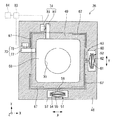
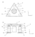
この走査型プローブ顕微鏡1は、倒立顕微鏡と組み合わせたものであり、図1(a)および(b)に示すように、基台としての除振台2に設置された本体部3と、この本体部3の上方に設けられた測定部4と、測定部4の下方に設けられた倒立顕微鏡8と、この測定部4の上方に設けられ、倒立顕微鏡8に連なる照明部5とを備えている。
This scanning probe microscope 1 is a combination with an inverted microscope, and as shown in FIGS. 1A and 1B, a
倒立顕微鏡8は、XYステージ31を介して除振台2に載置されている。
The
本体部3は、除振台2から垂直に延びる支柱12に支持された、平板状のベース13を備えて構成されるものである。ベース13の中央部には、ベース開口部15が形成されており、このベース開口部15内に、試料Sが載置されるステージ16が設けられており、このステージ16の中央にはステージ開口部17が形成されている。ステージ16は、後述するステージ微動機構部27により、Z方向に沿って微動するようになっている。なお、Z方向とは、試料Sの表面およびステージ16に垂直な方向であって、走査型プローブ顕微鏡1の高さ方向をいう。
The
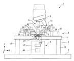
ステージ16の上面には、上述の測定部4が設置されている。測定部4は、後述するプローブ微動機構部26を備えており、このプローブ微動機構部26には、クランク状のクランク固定部30が設けられている。そして、クランク固定部30により、プローブ微動機構部26は、その中心がステージ開口部17に一致するように設置されている。
On the upper surface of the
なお、プローブ微動機構部26およびステージ微動機構部27は、走査型プローブ顕微鏡用微動機構を構成するものである。
The probe fine
プローブ微動機構部26の下面には、カンチレバー20を支持するカンチレバーホルダー22が設けられている。カンチレバーホルダー22の中央には、ガラスからなるガラスホルダ23が設けられている。このガラスホルダ23は、試料Sとガラスホルダ23との間に、液の粘性による膜を形成させて、これによって液中測定時の照明光の乱反射等を防止するためのものである。
A
なお、カンチレバー20は、長尺状のものに限定されず、上面視して三角形状のものや、断面が円形で光ファイバーの先端を先鋭化して湾曲させた近接場顕微鏡用のベントプローブなども本発明に含まれる。
Note that the
カンチレバー20は、ステージ開口部17の上方に設けられている。カンチレバー20の先端には、先鋭化されたプローブ21が設けられており、後端は、カンチレバーホルダー22に固定されている。これにより、カンチレバー20は、プローブ21が設けられた先端側が自由端となるように片持ち支持されている。また、カンチレバー20は、不図示の加振手段により、Z方向に沿って所定の周波数及び振幅で振動するようになっており、さらに、プローブ微動機構部26により、ステージ16に対して、X、Y方向に微動するようになっている。なお、XY方向とは、試料Sの表面およびステージ16に平行な互いに直交する方向であって、Z方向と直交する方向をいう。さらに、X方向とは、走査型プローブ顕微鏡1の幅方向をいい、Y方向とは、走査型プローブ顕微鏡1の奥行方向をいうものとする。
The
また、プローブ微動機構部26の近傍には、モーター37によってカンチレバー20をZ方向に粗動移動させるためのZ粗動機構部33が設けられており、Z粗動機構部33のベース部34が本体部3のベース13に固定されている。このZ粗動機構部33の上面にはXYステージ35が設けられており、このXYステージ35の上面に、前記クランク固定部30が固定されている。
Further, in the vicinity of the probe fine
また、プローブ微動機構部26の上方には、上述の照明部5が設けられている。照明部5は、照明光を発する光源40と、この光源40からの照明光を集光するためのコンデンサレンズ41とを備えている。コンデンサレンズ41は、倒立顕微鏡8に連なるレンズ支持部42によって、プローブ微動機構部26の中心上方に配されて、プローブ微動機構部26に対して上下動可能に支持されている。
In addition, the
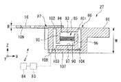
さらに、本実施例におけるプローブ微動機構部26は、図2に示すように、幅寸法の異なる矩形枠状の外フレーム部(フレーム部)48および内フレーム部(フレーム部)49を備えており、これら外フレーム部48および内フレーム部49は、低熱膨張鋳鉄によりフラット状に形成されている。また、外フレーム部48と内フレーム部49とは、X駆動部(第1の駆動部)52とY駆動部(第1の駆動部)51とを介して、互いに同心上に連結されており、外フレーム部48および内フレーム部49の上面は面一にして配されている。X駆動部52は、外フレーム部48に形成されたY方向に延びるX側空洞部60内に設置されており、Y駆動部51は、同様にX方向に延びるY側空洞部57内に設置されている。
Furthermore, as shown in FIG. 2, the probe fine
X駆動部52は、Y方向に向けられた積層型のX側圧電素子61を備えている。X側圧電素子61には、その周囲を取り囲むように、上面視して略ひし形のX側変位拡大機構部62が設けられている。そして、X側変位拡大機構部62は、X側連結部63を介して、内フレーム部49に連結されている。
The
また、Y駆動部51は、X方向に向けられた積層型のY側圧電素子54を備えている。Y側圧電素子54には、上記と同様に、略ひし形のY側変位拡大機構部55が設けられており、Y側変位拡大機構部55は、Y側連結部56を介して、内フレーム部49に連結されている。
The
内フレーム部49の四隅には、平行バネ67が設置されている。
Parallel springs 67 are installed at the four corners of the
このような構成のもと、X側圧電素子61およびY側圧電素子54に電圧を印加することにより、X側変位拡大機構部62およびY側変位拡大機構部55が、それぞれX方向、Y方向に拡大縮小し、これにより内フレーム部49をXY方向に微動させるようになっている。
Under such a configuration, by applying a voltage to the X-side
また、内フレーム部49の底面には、略矩形の基板部68が設けられている。基板部68の中央には、Z方向に向けられたプローブ側貫通孔70が形成されている。そして、このプローブ側貫通孔70に、図1に示す光源40からの照明光が通されるようになっている。
Further, a substantially
なお、基板部68の下面に、上述したように、カンチレバーホルダー22を介してカンチレバー20が設けられており、内フレーム部49のXY方向の微動により、基板部68およびカンチレバーホルダー22とともに、カンチレバー20もXY方向に微動するようになっている。
As described above, the
また、外フレーム部48および内フレーム部49の上面には、Y方向微動量検出部73およびX方向微動量検出部74が設けられている。Y方向微動量検出部73は、内フレーム部49に固定され、X方向に延びるY方向ターゲット77と、外フレーム部48に固定され、Y方向ターゲット77のY方向の移動量を検出するY方向センサ78とを備えている。また、X方向微動量検出部74は、同様にしてY方向に延びるX方向ターゲット80と、X方向ターゲット80のY方向の移動量を検出するX方向センサ81とを備えている。これらY方向センサ78およびX方向センサ81としては、静電容量センサが用いられるが、これに限定されるものではなく、ひずみゲージや光学式変位系、差動トランスなどでもよい。
A Y-direction fine movement
このような構成のもと、内フレーム部49がX方向に微動すると、X方向ターゲット80もX方向に微動し、そのX方向の微動量をX方向センサ81が検出するようになっている。また、内フレーム部49がY方向に微動すると、Y方向ターゲット77もY方向に微動し、そのY方向の微動量をY方向センサ78が検出するようになっている。すなわち、X方向センサ81は、X方向ターゲット80および内フレーム部49を介して、カンチレバー20のX方向の微動量を検出し、Y方向センサ78は、またY方向ターゲット77および内フレーム部49を介して、カンチレバー20のY方向の微動量を検出する微動量検出手段として機能するものである。
Under such a configuration, when the
X方向センサ81およびY方向センサ78は、それぞれ演算部(算出手段)83に電気的に接続されており、X方向センサ81およびY方向センサ78からの検出結果が、演算部83に入力されるようになっている。演算部83は、検出結果に応じて、印加された電圧と微動量とによって、カンチレバー20のXY方向の微動量の誤差を算出するようになっている。すなわち、演算部83は算出手段として機能するものである。さらに、演算部83は、各種制御を行う制御部84に電気的に接続されており、算出結果を制御部84に入力するようになっている。そして、この制御部84によって、印加電圧に対して、プローブ微動機構部27が線形に動作するように制御される。
The
また、プローブ微動機構部26には、図1に示すように、レーザ光を発するレーザ光源(プローブ変位検出手段)44と、このレーザ光源44からのレーザ光を受光し、例えば4分割されたフォトディテクタ(プローブ変位検出手段)45とが設けられている。これらレーザ光源44およびフォトディテクタ45は、カンチレバー20の斜め上方に互いに対向して配置されている。そして、レーザ光源44から出射されたレーザ光が、カンチレバー20の上面に到達してそこで反射し、その反射光がフォトディテクタ45に到達するようになっている。
Further, as shown in FIG. 1, the probe fine
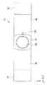
さらに、本実施例におけるステージ微動機構部27は、図3および図4に示すように、略長方形状に形成された機構本体部86と、この機構本体部86から、機構本体部86の厚さ方向(すなわちZ方向)に交差する方向(すなわちX方向)に延出する延出部87とを備えている。
Further, as shown in FIGS. 3 and 4, the stage fine
延出部87の厚さ寸法Rは、機構本体部の厚さ寸法Mよりも小さく設定されている。そして、延出部87の上面と機構本体部86の上面とは略同一にされており、これにより、延出部87の下方には、スペースJが設けられている。
The thickness dimension R of the extending
延出部87には、Z方向に向けられたステージ側貫通孔109が形成されており、このステージ側貫通孔109内に、上述のステージ16が載せられている。
A stage side through
機構本体部86には、延出部87の延出方向と反対方向に延びる本体固定部91が設けられている。本体固定部91は、図1に示すベース13の所定の位置に固定されており、これにより、機構本体部86が片持ち支持されている。
The mechanism
また、機構本体部86の内部には、空洞部93が設けられている。空洞部93の上内壁部94のX方向の両端のうち、本体固定部91が設けられた方の端部には、第1平行バネ101が設けられており、延出部87が設けられた方の端部には、第2平行バネ102が設けられている。一方、下内壁部97のX方向の両端のうち、延出部87が設けられた方の端部には、第3平行バネ103が、本体固定部91が設けられた方の端部には、第4平行バネ104が設けられている。また、第2平行バネ102の近傍には、上内壁部94から下方に向けて延びる下方壁部95が設けられており、第4平行バネ104の近傍には、下内壁部97から上方に向けて延びる上方壁部96が設けられている。すなわち、下方壁部95および上方壁部96が、互いに反対方向に延ばされて対向して配置されている。
A cavity 93 is provided inside the mechanism
そして、これら下方壁部95と上方壁部96との間に、Z駆動部(第2の駆動部)85が設けられている。Z駆動部85は、X駆動部52およびY駆動部51とは、物理的に分離して別個に設けられたものであり、それぞれ独立して機能するものである。Z駆動部85は、X方向に向けられた積層型のZ側圧電素子90からなるものである。そして、Z側圧電素子90は、その一端が下方壁部95に固定され、他端が上方壁部96に固定されている。さらに、機構本体部86の下端には、X方向に延びる底壁部107が設けられている。この底壁部107のX方向の両端のうち、本体固定部91が設けられた方の端部は、機構本体部86の側壁に一体的に固定されており、延出部87が設けられた方の端部は、自由端となっている。この底壁部107の先端部には、演算部83に接続されたZ方向微動量検出部108が設けられている。Z方向微動量検出部108には、静電容量センサが用いられるが、これに限定されるものではなく、ひずみゲージや光学式変位系、差動トランスなどでもよい。
A Z driving unit (second driving unit) 85 is provided between the
このような構成のもと、Z側圧電素子90に電圧を印加すると、Z側圧電素子90が伸縮するようになっている。そして、Z側圧電素子90が伸びると、下方壁部95および上方壁部96がX方向外方に押圧され、上方壁部96は固定端付近を中心に図3における時計方向に回転するとともに、下方壁部95も固定端付近を中心に時計方向に回転し、結果として、第1から第4の平行バネ101,102,103,104に案内されて、延出部87がZ方向に移動し、延出部87に連結されたステージ16がZ方向に移動するようになっている。このとき、Z方向微動量検出部108により、機構本体部86の微動量が検出されるようになっている。すなわち、Z方向微動量検出部108は、機構本体部86を介して、ステージ16のZ方向の微動量を検出する微動量検出手段として機能するものである。そして、演算部83が、Z方向微動量検出部108の検出結果に応じて、印加された電圧と実際の微動量とによって、ステージ16のZ方向の微動量の誤差を算出するようになっている。この算出結果は制御部84に入力され、この制御部84によって、印加電圧に対して、ステージ微動機構部27が線形に動作するように制御される。
Under such a configuration, when a voltage is applied to the Z-side
なお、Z方向については、単にZ方向微動量検出部108により微動量を検出し、それを走査型プローブ顕微鏡の高さ上方として表示させてもよい。
As for the Z direction, the amount of fine movement may be simply detected by the Z direction fine movement
このように構成されたステージ微動機構27は、小型かつ高剛性であり、プローブ微動機構部26に比べて共振周波数が高く高速動作が可能となっている。
The stage
さらに、本実施例においては、図1に示すように、スペースJに対物レンズ10が設けられている。すなわち、倒立顕微鏡8の上端に、レボルバ(配置変更手段)9が設けられており、このレボルバ9に、それぞれ倍率の異なる複数の対物レンズ10が設けられている。そして、レボルバ9を回すことにより、複数の対物レンズ10の配置が変更されるようになっており、複数の対物レンズ10をスペースJ内の観察位置Kに選択的に配置することができるようになっている。観察位置Kとは、ステージ16の下方であって、ステージ開口部17に一致する位置をいい、試料Sを観察するための位置をいう。
Further, in this embodiment, as shown in FIG. 1, an
また、対物レンズ10は、観察位置Kにおいて、倒立顕微鏡8に設けられたフォーカシングダイヤル8aを操作することによりZ方向に上下動することができるようになっている。
The
次に、このように構成された本実施例における走査型プローブ顕微鏡1の作用について説明する。 Next, the operation of the scanning probe microscope 1 in the present embodiment configured as described above will be described.
まず、試料Sを不図示の液中セルを介してステージ16に載置する。そして、光源40をオンにし、試料Sに向けて照明光を照射する。すると、その照明光は、プローブ側貫通孔70を通り、試料Sを透過して、さらにステージ側貫通孔109を通ることにより、観察位置Kに配された対物レンズ10に到達する。これによって、対物レンズ10を介して、試料Sの状態が観察される。このとき、レボルバ9を回すと、はじめの対物レンズ10がスペースJを通って観察位置Kから外れ、他の対物レンズ10が観察位置Kに配置される。これにより、適切な倍率の対物レンズ10が選択される。また、フォーカシングダイヤル8aを操作すると、対物レンズ10が上方に移動し、対物レンズ10が試料Sに近接し、フォーカシングされる。
First, the sample S is placed on the
これによって試料Sの初期観察が行われ、この結果に応じて、詳細測定が行われる。 Thereby, the initial observation of the sample S is performed, and detailed measurement is performed according to the result.
詳細測定を行うには、試料Sの表面とプローブ21の位置を、倒立顕微鏡8の像を見ながら、XYステージ35で位置合わせをする。次に、レーザ光源44およびフォトディテクタ45の位置を調整する。すなわち、レーザ光源44から照射したレーザ光Lが、カンチレバー20の上面で反射し、フォトディテクタ45に確実に入射するよう位置調整を行う。それから、モータ37を駆動して、Z粗動機構部33により、カンチレバー20を粗動移動させて、カンチレバー20を液中セルの培養液に浸漬させる。そして、プローブ21を試料Sの表面近傍に位置させる。
In order to perform detailed measurement, the surface of the sample S and the position of the
この状態から、加振手段により、カンチレバー20を介してプローブ21を、Z方向に沿って所定の周波数および振幅で振動させる。そして、図2に示すX側圧電素子61およびY側圧電素子54に電圧を印加する。すると、X側圧電素子61およびY側圧電素子54が伸縮し、X側変位拡大機構部62およびY側変位拡大機構部55を介して、内フレーム部49がXY方向に微動する。これにより、プローブ21が試料S上を所定の走査速度でラスタースキャンする。
From this state, the vibration means causes the
このとき、内フレーム部49がXY方向に微動すると、X方向ターゲット81およびY方向ターゲット78がそれぞれX方向、Y方向に微動し、そのX、Y方向の微動量がX方向センサ81およびY方向センサ78によって検出される。これら検出結果は演算部83に入力されて、カンチレバー20のXY方向の微動量の誤差が算出され、この算出結果が制御部84に入力される。このように、XY方向の微動量を補正することによって、X側圧電素子61やY側圧電素子54のヒステリシスやクリープに影響されず、XY方向に線形に動作する。
At this time, when the
走査の際、試料Sの凹凸に応じて、プローブ21と試料Sの表面との距離が変わると、原子間力や間欠的な接触力によりプローブ21が斥力または引力を受けるので、カンチレバー20の振動状態が変化し、振巾や位相が変わる。この振巾や位相の変化は、フォトディテクタ45の異なる2対の分割面の出力差(DIF信号と呼ぶ)として検出される。このDIF信号は、不図示のZ電圧フィードバック回路に入力される。そして、Z電圧フィードバック回路は、DIF信号により振巾や位相が同じになるように、図3に示すZ側圧電素子90に電圧を印加する。
When scanning, if the distance between the
Z側圧電素子90は、電圧が印加されることにより高速で伸縮を繰り返す。Z側圧電素子90が伸縮すると、延出部87を介してステージ16が非常に高い周波数でZ方向に移動し、ステージ16上の試料SがZ方向に移動する。これにより、上記走査の際、プローブ21と試料Sの表面との間の距離が常に一定に保たれる。
The Z-side
また、ステージ16がZ方向に移動すると、Z方向微動量検出部108により、機構本体部86の微動量が検出され、この検出結果に応じて、ステージ16のZ方向の微動量の誤差が算出される。そして、その算出結果が制御部84に入力され、Z方向に線形に動作させることができる。
When the
なお、Z方向移動量検出部108により微動量を検出し、それを走査型プローブ顕微鏡の高さ情報として表示させてもよい。この場合、より高速走査が可能となる。
Note that the fine movement amount may be detected by the Z-direction movement
このようにして、X側、Y側、Z側圧電素子61、54、90に印加した電圧、またはX方向、Y方向、Z方向センサ81、78、108の信号を制御部84に入力し、画像化することで試料Sの表面の形状像を測定することができる。また、プローブ21と試料Sとの間に働くいろいろな力や物理作用を測定することで、粘弾性、試料Sの表面電位分布、試料Sの表面の漏れ磁界分布、近接場光学像等の各種の物性情報の測定を行うことができる。
In this way, the voltage applied to the X-side, Y-side, and Z-side
以上より、本実施例における走査型プローブ顕微鏡1によれば、Z駆動部85が、X駆動部52およびY駆動部51とは、物理的に分離して別個に設けられたものであり、それぞれ独立して機能させることができることから、Z側圧電素子90の共振周波数をX側圧電素子61およびY側圧電素子54よりも高く設定することができる。そのため、プローブ21の走査速度を速くしても、ステージ16を充分に追従させることができ、全体の走査スピードを向上させることができる。
As described above, according to the scanning probe microscope 1 in the present embodiment, the Z driving unit 85 is physically separated from the
また、それぞれ独立して機能させることから、Z側圧電素子90の動きがX側圧電素子61およびY側圧電素子54によって影響を受けないようにすることができる。そのため、走査スピードを向上させつつ、測定精度を向上させることができる。
ここで、ステージ16には試料Sが載せられるだけなのに対して、カンチレバー20側には、カンチレバーホルダー22やレーザ光源44、フォトダイオード45などの多くの部品が設けられるため、カンチレバー20側の機構は、全体的に大きくかつ重くなるのが一般的である。そのため、カンチレバー20側に、走査速度が遅くてもよいプローブ微動機構部26を設け、より高速応答性が必要なステージ16側に、ステージ微動機構部27を設けることで、より一層走査スピードを向上させることができる。In addition, since each of them functions independently, the movement of the Z side
Here, while the sample S is merely placed on the
また、プローブ微動機構部26には、変位検出手段としてのレーザ光源44およびフォトディテクタ45が設けられていることから、カンチレバー20を微動させながら、カンチレバー20の変位量を確実に測定することができる。
Further, since the probe fine
なお、変位検出手段は、この方式に限定されず、例えば、カンチレバー20自体に抵抗体を設けて、カンチレバー20の撓みに伴う抵抗値変化により測定を行う方式なども本発明に含まれる。
The displacement detection means is not limited to this method, and for example, a method in which a resistor is provided in the
また、プローブ微動機構部26には、プローブ側貫通孔70が設けられ、このプローブ側貫通孔70に照明光を通していることから、照明光の進行を邪魔することなく、高精度に測定することができる。
Further, the probe fine
さらに、プローブ微動機構部26は、外フレーム部48および内フレーム部49によってフラット状に形成されているため、全体を小さく薄くすることができる。したがって、ワークディスタンスの短い、より高NAのコンデンサレンズを配置することができ、倒立顕微鏡8の分解能を向上させることができる。
Further, since the probe fine
また、X方向微動量検出部74、Y方向微動量検出部73およびZ方向微動量検出部108により、XYZ方向の微動量の誤差を検出し、プローブ微動機構部26とステージ微動機構部27を線形動作させることができるため、より高精度な測定を行うことができる。
Further, the X-direction fine movement
さらに、レボルバ9を介して複数の対物レンズ10が設けられており、レボルバ9を回すことにより、複数の対物レンズ10を観察位置Kに選択的に配することができることから、適切な倍率の対物レンズ10を容易かつ迅速に配置することができる。
Further, a plurality of
また、対物レンズ10を試料Sに一層近接させることができ、高NAの対物レンズを設けて高精度な測定を行うことができる。
Further, the
また、延出部87の厚さ寸法Rを機構本体部86の厚さ寸法Mよりも小さく設定して、延出部87の下方にスペースJを設けたことから、このスペースJを有効活用することができる。本実施例においては、スペースJに対物レンズ10を配置したことによって、レボルバ9の回転が邪魔されることなく、簡単かつ迅速に対物レンズ10の配置変更をすることができる。したがって、倒立顕微鏡8の操作性を向上させることができる。
Further, since the thickness dimension R of the extending
さらに、機構本体部86を介してステージ微動機構部27が片持ち支持されていることから、簡易な構成により充分なスペースJを確保することができる。
Furthermore, since the stage
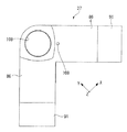
なお、本実施例においては、ステージ微動機構部27が片持ち支持されるとしたが、これに限ることはなく、例えば、図5に示すように、機構本体部86をX方向に並べて、その間に延出部87を配置する構成として、X方向両端の本体固定部91によって、両持ち支持するようにしてもよい。また、図6に示すように、機構本体部86をそれぞれXY方向に向けて互いに90度になるように配置する構成とし、本体固定部91によって両持ち支持するようにしてもよい。
In this embodiment, the stage
さらに、図7に示すようなアクチュエータを複数本利用したステージ微動機構27でもよい。図7(a)はこのステージ微動機構の平面図、図7(b)は正面図である。このステージ微動機構27では同じ形状で同一の移動特性を有する3本のアクチュエータである積層型圧電素子120を平面視で三角形型に配置し、積層型圧電素子120の末端120bをベース13に固定し、移動端120aに試料Sを載置するためのステージ121を磁石125により固定した構造であり、ステージ121には貫通孔122が設けられ、積層型圧電素子120で囲まれる空間123には対物レンズ10が配置された構成である。各々の積層型圧電素子120に電圧を印加すると、ステージ121は試料S表面に垂直な方向に移動する。
Further, a stage
このように構成されたステージ移動機構27においては、ステージ121が3本の積層型圧電素子120により支持されているため、ステージ121の剛性を高めることができ、Z方向の移動を高速に行うことが可能となる。また、3本の積層型圧電素子120で囲まれる空間123内に、対物レンズ10を配置したり、空間部分から照明光を試料Sに照射することが可能となる。また、隣り合う積層型圧電素子120の間124を通して、対物レンズ配置変換手段(図示せず)により対物レンズ10の交換も行うことが可能となる。
(実施例2)
次に、本発明の第2の実施例について説明する。In the
(Example 2)
Next, a second embodiment of the present invention will be described.
図8は、本発明の第2の実施例を示したものである。 FIG. 8 shows a second embodiment of the present invention.
図8において、図1から図7に記載の構成要素と同一部分については同一符号を付し、その説明を省略する。 In FIG. 8, the same components as those shown in FIGS. 1 to 7 are denoted by the same reference numerals, and the description thereof is omitted.
この実施例と上記第1の実施例とは基本的構成は同一であり、以下の点において異なるものとなっている。 This embodiment and the first embodiment have the same basic configuration, and differ in the following points.
すなわち、本実施例における走査型プローブ顕微鏡1は、正立顕微鏡と組み合わせたものである。すなわち、正立顕微鏡8には光源40が設けられ、光源40の上端にはコンデンサレンズ41が設けられている。また、コンデンサレンズ41の上方にはステージ微動機構部27が設けられている。ステージ微動機構部27は円筒状のZ側圧電素子90からなり、Z側圧電素子90はZ方向に向けて設置されている。Z側圧電素子90には、Z方向に向けられた筒孔(ステージ側貫通孔)110が形成されており、この筒孔110に光源40からの照明光が通されるようになっている。
That is, the scanning probe microscope 1 in this embodiment is combined with an upright microscope. That is, the
また、プローブ微動機構部26の上方には、観察位置Kに対物レンズ10が設けられている。ここでの観察位置Kとは、プローブ微動機構部26の上方から、カンチレバー20または試料Sを観察する位置をいう。対物レンズ10は、観察位置Kにおいて上下動するようになっており、下方に移動させると、プローブ側貫通孔70に挿入されるようになっている。
The
このような構成のもと、光源40からの照明光は、筒孔110を通って試料Sを透過する。また、対物レンズ10を下方に移動させて、プローブ側貫通孔70に挿入すると、対物レンズ10はカンチレバー20または試料Sに近接する。
Under such a configuration, the illumination light from the
以上より、ステージ微動機構部27には筒孔110が設けられ、この筒孔110に照明光を通していることから、照明光の進行を邪魔することなく、高精度に測定することができる。
As described above, the stage fine
また、この対物レンズ10を、プローブ側貫通孔70に挿入することができることから、カンチレバー20や試料Sに対物レンズ10を一層近接させることができ、高NAの対物レンズを設けて高精度な測定を行うことができる。
In addition, since the
なお、上記第1および第2の実施例では、X側圧電素子61、Y側圧電素子54およびZ側圧電素子90を積層型の圧電素子としたが、これに限ることはなく、適宜変更可能である。例えば、スタック型の圧電素子としたり、またはボイスコイルなどを用いたりすることも可能である。
In the first and second embodiments, the X-side
また、プローブ微動機構部26またはステージ微動機構部27に、円筒状の圧電素子を用いることも可能である。
Further, a cylindrical piezoelectric element can be used for the probe fine
また、DFMモードによる観察としたが、これに限ることはなく、コンタクトAFMなどの種々のモードに適用可能である。さらに、近接場顕微鏡にも適用することができる。近接場顕微鏡に適用すると、高NAの対物レンズを使用することができるため、近接場信号の集光効率を向上させることができる。 In addition, although observation is performed in the DFM mode, the present invention is not limited to this, and can be applied to various modes such as contact AFM. Furthermore, it can be applied to a near-field microscope. When applied to a near-field microscope, an objective lens having a high NA can be used, so that the efficiency of collecting near-field signals can be improved.
さらに、液中測定としたが、これに限ることはなく、大気中であってもよい。 Furthermore, although it was set as the measurement in a liquid, it is not restricted to this, You may be in air | atmosphere.
なお、本発明の技術範囲は上記実施例に限定されるものではなく、本発明の趣旨を逸脱しない範囲において、種々の変更を加えることが可能である。 The technical scope of the present invention is not limited to the above-described embodiments, and various modifications can be made without departing from the spirit of the present invention.
Claims (18)
前記試料の表面に平行な互いに交差するX方向およびY方向に前記プローブを微動させる第1の駆動部を有するプローブ微動機構部と、
前記試料の表面に垂直なZ方向に前記ステージを微動させる、前記第1の駆動部とは独立して設けられた第2の駆動部を有するステージ微動機構部と、を備え、
前記プローブ微動機構部が、前記プローブの変位を検出するプローブ変位検出手段を含み、前記Z方向に向けられたプローブ側貫通孔を有し、
前記プローブの直上に対物レンズまたはコンデンサレンズを有することを特徴とする走査型プローブ顕微鏡用微動機構。In a fine movement mechanism for a scanning probe microscope provided in a scanning probe microscope having a stage on which a sample is placed and a probe that is brought close to or in contact with the surface of the sample,
A probe fine movement mechanism having a first drive unit for finely moving the previous SL probe in X and Y directions intersecting parallel to each other on the surface of the sample,
Finely moving the previous SL stage Z direction perpendicular to the surface of the sample, and a stage fine movement mechanism portion having a second driving unit which is provided independently of said first drive unit,
The probe fine movement mechanism includes probe displacement detection means for detecting displacement of the probe, and has a probe-side through hole directed in the Z direction,
A fine movement mechanism for a scanning probe microscope, comprising an objective lens or a condenser lens immediately above the probe .
該延出部の厚さ寸法が、前記機構本体部の厚さ寸法より小さい請求項1〜3のいずれか一項に記載の走査型プローブ顕微鏡用微動機構。The stage fine movement mechanism section has a mechanism main body section having the second drive section, and an extension section that extends from the mechanism main body section in a direction intersecting the thickness direction of the mechanism main body section and supports the stage. And
The fine movement mechanism for a scanning probe microscope according to any one of claims 1 to 3 , wherein a thickness dimension of the extension part is smaller than a thickness dimension of the mechanism main body part.
Priority Applications (1)
| Application Number | Priority Date | Filing Date | Title |
|---|---|---|---|
| JP2007504663A JP5111102B2 (en) | 2005-02-24 | 2006-02-10 | Fine movement mechanism for scanning probe microscope and scanning probe microscope using the same |
Applications Claiming Priority (4)
| Application Number | Priority Date | Filing Date | Title |
|---|---|---|---|
| JP2005048262 | 2005-02-24 | ||
| JP2005048262 | 2005-02-24 | ||
| JP2007504663A JP5111102B2 (en) | 2005-02-24 | 2006-02-10 | Fine movement mechanism for scanning probe microscope and scanning probe microscope using the same |
| PCT/JP2006/302316 WO2006090594A1 (en) | 2005-02-24 | 2006-02-10 | Inching mechanism for scanning probe microscope and scanning probe microscope employing it |
Publications (2)
| Publication Number | Publication Date |
|---|---|
| JPWO2006090594A1 JPWO2006090594A1 (en) | 2008-07-24 |
| JP5111102B2 true JP5111102B2 (en) | 2012-12-26 |
Family
ID=36927236
Family Applications (1)
| Application Number | Title | Priority Date | Filing Date |
|---|---|---|---|
| JP2007504663A Expired - Fee Related JP5111102B2 (en) | 2005-02-24 | 2006-02-10 | Fine movement mechanism for scanning probe microscope and scanning probe microscope using the same |
Country Status (4)
| Country | Link |
|---|---|
| US (1) | US7614288B2 (en) |
| JP (1) | JP5111102B2 (en) |
| DE (1) | DE112006000456T5 (en) |
| WO (1) | WO2006090594A1 (en) |
Families Citing this family (7)
| Publication number | Priority date | Publication date | Assignee | Title |
|---|---|---|---|---|
| JP4660782B2 (en) * | 2005-10-31 | 2011-03-30 | セイコーインスツル株式会社 | Liquid cell |
| DE202008013982U1 (en) * | 2008-10-20 | 2009-01-08 | Rosenberger Hochfrequenztechnik Gmbh & Co. Kg | Measuring system for determining scattering parameters |
| EP2367016A4 (en) * | 2008-12-10 | 2014-03-05 | Univ Kyoto | PROCESS FOR PROCESSING OUTPUT OF NEAR-FIELD MICROSCOPE, AND NEAR-FIELD MICROSCOPE |
| JP5909020B2 (en) * | 2012-03-27 | 2016-04-26 | ハイジトロン, インク.Hysitron, Inc. | Microscope objective lens machine inspection equipment |
| JP6638124B2 (en) * | 2014-09-26 | 2020-01-29 | 有限会社メカノトランスフォーマ | Stage device and drive mechanism used for same |
| CN110108627A (en) * | 2019-05-21 | 2019-08-09 | 苏州大学 | A kind of cell in-situ observation and operating device based on microsphere lens |
| GB2626604A (en) * | 2023-01-30 | 2024-07-31 | Lig Nanowise Ltd | Sample support system |
Citations (5)
| Publication number | Priority date | Publication date | Assignee | Title |
|---|---|---|---|---|
| JPH08285865A (en) * | 1995-04-13 | 1996-11-01 | Olympus Optical Co Ltd | Scanning probe microscope |
| JPH0933543A (en) * | 1995-07-14 | 1997-02-07 | Olympus Optical Co Ltd | Scanning near-field optical microscope |
| JPH1090610A (en) * | 1996-09-17 | 1998-04-10 | Olympus Optical Co Ltd | Scan type probe microscope |
| JPH11133040A (en) * | 1997-10-31 | 1999-05-21 | Hitachi Constr Mach Co Ltd | Fine motion mechanism apparatus and scanning type probe microscope |
| JP2004257849A (en) * | 2003-02-26 | 2004-09-16 | Seiko Instruments Inc | Scanning mechanism for scanning probe microscope, and scanning probe microscope |
Family Cites Families (5)
| Publication number | Priority date | Publication date | Assignee | Title |
|---|---|---|---|---|
| DE3856575T2 (en) * | 1987-08-12 | 2005-11-10 | Olympus Optical Co., Ltd. | Scanning tunneling microscope |
| EP0783662B1 (en) * | 1994-08-27 | 1999-04-07 | International Business Machines Corporation | Fine positioning apparatus with atomic resolution |
| US6246652B1 (en) * | 1997-12-05 | 2001-06-12 | Hitachi, Ltd. | Device using sensor for small rotation angle |
| JP2000346784A (en) | 1999-06-04 | 2000-12-15 | Shimadzu Corp | Viscoelastic distribution measurement method |
| US6612160B2 (en) * | 2001-03-09 | 2003-09-02 | Veeco Instruments, Inc. | Apparatus and method for isolating and measuring movement in metrology apparatus |
-
2006
- 2006-02-10 JP JP2007504663A patent/JP5111102B2/en not_active Expired - Fee Related
- 2006-02-10 DE DE112006000456T patent/DE112006000456T5/en not_active Withdrawn
- 2006-02-10 WO PCT/JP2006/302316 patent/WO2006090594A1/en not_active Ceased
-
2007
- 2007-08-21 US US11/842,735 patent/US7614288B2/en not_active Expired - Fee Related
Patent Citations (5)
| Publication number | Priority date | Publication date | Assignee | Title |
|---|---|---|---|---|
| JPH08285865A (en) * | 1995-04-13 | 1996-11-01 | Olympus Optical Co Ltd | Scanning probe microscope |
| JPH0933543A (en) * | 1995-07-14 | 1997-02-07 | Olympus Optical Co Ltd | Scanning near-field optical microscope |
| JPH1090610A (en) * | 1996-09-17 | 1998-04-10 | Olympus Optical Co Ltd | Scan type probe microscope |
| JPH11133040A (en) * | 1997-10-31 | 1999-05-21 | Hitachi Constr Mach Co Ltd | Fine motion mechanism apparatus and scanning type probe microscope |
| JP2004257849A (en) * | 2003-02-26 | 2004-09-16 | Seiko Instruments Inc | Scanning mechanism for scanning probe microscope, and scanning probe microscope |
Also Published As
| Publication number | Publication date |
|---|---|
| DE112006000456T5 (en) | 2008-01-17 |
| WO2006090594A1 (en) | 2006-08-31 |
| US20080061232A1 (en) | 2008-03-13 |
| JPWO2006090594A1 (en) | 2008-07-24 |
| US7614288B2 (en) | 2009-11-10 |
Similar Documents
| Publication | Publication Date | Title |
|---|---|---|
| US8302456B2 (en) | Active damping of high speed scanning probe microscope components | |
| US8296856B2 (en) | Control system for scanning probe microscope | |
| US20100180356A1 (en) | Nanoindenter | |
| JP2005517911A (en) | Scanning probe microscope | |
| CN101960287A (en) | The scanning probe microscopy of quick scanning and the method that operates on it | |
| KR102698740B1 (en) | Specimen container holding device for scanning probe microscope | |
| US7614288B2 (en) | Scanning probe microscope fine-movement mechanism and scanning probe microscope using same | |
| KR101198178B1 (en) | High-Speed and High-Resolution Atomic Force Microscope | |
| US20140317790A1 (en) | Optical beam positioning unit for atomic force microscope | |
| US7614287B2 (en) | Scanning probe microscope displacement detecting mechanism and scanning probe microscope using same | |
| US6194813B1 (en) | Extended-range xyz linear piezo-mechanical scanner for scanning-probe and surface force applications | |
| US6437343B1 (en) | Scanner system and piezoelectric micro-inching mechansim used in scanning probe microscope | |
| JP4914580B2 (en) | Scanning probe microscope | |
| JP4575250B2 (en) | Scanning probe microscope | |
| JP3892184B2 (en) | Scanning probe microscope | |
| US10564181B2 (en) | Atomic force microscope with optical guiding mechanism | |
| JP2007003246A (en) | Scanning probe microscope | |
| JP2004069445A (en) | Scanning type probe microscope | |
| Cai et al. | A mini review of the key components used for the development of high-speed atomic force microscopy | |
| JP4162508B2 (en) | Scanning mechanism for scanning probe microscope and scanning probe microscope | |
| JP2006023443A (en) | Microscope system | |
| JP3512259B2 (en) | Scanning probe microscope | |
| WO2021044934A1 (en) | Scanning probe microscope and driving control device for scanning probe microscope | |
| JPWO2018131343A1 (en) | Scanner and scanning probe microscope | |
| JP2008102151A (en) | Scanning mechanism for scanning probe microscope and scanning probe microscope |
Legal Events
| Date | Code | Title | Description |
|---|---|---|---|
| A621 | Written request for application examination |
Free format text: JAPANESE INTERMEDIATE CODE: A621 Effective date: 20081007 |
|
| RD01 | Notification of change of attorney |
Free format text: JAPANESE INTERMEDIATE CODE: A7421 Effective date: 20091105 |
|
| RD01 | Notification of change of attorney |
Free format text: JAPANESE INTERMEDIATE CODE: A7421 Effective date: 20091113 |
|
| RD01 | Notification of change of attorney |
Free format text: JAPANESE INTERMEDIATE CODE: A7421 Effective date: 20091118 |
|
| A072 | Dismissal of procedure [no reply to invitation to correct request for examination] |
Free format text: JAPANESE INTERMEDIATE CODE: A073 Effective date: 20091222 |
|
| A131 | Notification of reasons for refusal |
Free format text: JAPANESE INTERMEDIATE CODE: A131 Effective date: 20110906 |
|
| A521 | Request for written amendment filed |
Free format text: JAPANESE INTERMEDIATE CODE: A523 Effective date: 20111104 |
|
| TRDD | Decision of grant or rejection written | ||
| A01 | Written decision to grant a patent or to grant a registration (utility model) |
Free format text: JAPANESE INTERMEDIATE CODE: A01 Effective date: 20121002 |
|
| A01 | Written decision to grant a patent or to grant a registration (utility model) |
Free format text: JAPANESE INTERMEDIATE CODE: A01 |
|
| A61 | First payment of annual fees (during grant procedure) |
Free format text: JAPANESE INTERMEDIATE CODE: A61 Effective date: 20121009 |
|
| FPAY | Renewal fee payment (event date is renewal date of database) |
Free format text: PAYMENT UNTIL: 20151019 Year of fee payment: 3 |
|
| R150 | Certificate of patent or registration of utility model |
Ref document number: 5111102 Country of ref document: JP Free format text: JAPANESE INTERMEDIATE CODE: R150 Free format text: JAPANESE INTERMEDIATE CODE: R150 |
|
| FPAY | Renewal fee payment (event date is renewal date of database) |
Free format text: PAYMENT UNTIL: 20151019 Year of fee payment: 3 |
|
| S531 | Written request for registration of change of domicile |
Free format text: JAPANESE INTERMEDIATE CODE: R313531 |
|
| S533 | Written request for registration of change of name |
Free format text: JAPANESE INTERMEDIATE CODE: R313533 |
|
| FPAY | Renewal fee payment (event date is renewal date of database) |
Free format text: PAYMENT UNTIL: 20151019 Year of fee payment: 3 |
|
| R371 | Transfer withdrawn |
Free format text: JAPANESE INTERMEDIATE CODE: R371 |
|
| FPAY | Renewal fee payment (event date is renewal date of database) |
Free format text: PAYMENT UNTIL: 20151019 Year of fee payment: 3 |
|
| S531 | Written request for registration of change of domicile |
Free format text: JAPANESE INTERMEDIATE CODE: R313531 |
|
| S533 | Written request for registration of change of name |
Free format text: JAPANESE INTERMEDIATE CODE: R313533 |
|
| FPAY | Renewal fee payment (event date is renewal date of database) |
Free format text: PAYMENT UNTIL: 20151019 Year of fee payment: 3 |
|
| R350 | Written notification of registration of transfer |
Free format text: JAPANESE INTERMEDIATE CODE: R350 |
|
| R250 | Receipt of annual fees |
Free format text: JAPANESE INTERMEDIATE CODE: R250 |
|
| R250 | Receipt of annual fees |
Free format text: JAPANESE INTERMEDIATE CODE: R250 |
|
| R250 | Receipt of annual fees |
Free format text: JAPANESE INTERMEDIATE CODE: R250 |
|
| R250 | Receipt of annual fees |
Free format text: JAPANESE INTERMEDIATE CODE: R250 |
|
| LAPS | Cancellation because of no payment of annual fees |