JP5111304B2 - Discharge container with sliding bottom plate - Google Patents
Discharge container with sliding bottom plate Download PDFInfo
- Publication number
- JP5111304B2 JP5111304B2 JP2008221780A JP2008221780A JP5111304B2 JP 5111304 B2 JP5111304 B2 JP 5111304B2 JP 2008221780 A JP2008221780 A JP 2008221780A JP 2008221780 A JP2008221780 A JP 2008221780A JP 5111304 B2 JP5111304 B2 JP 5111304B2
- Authority
- JP
- Japan
- Prior art keywords
- cylinder
- bottom plate
- sliding bottom
- plate
- container
- Prior art date
- Legal status (The legal status is an assumption and is not a legal conclusion. Google has not performed a legal analysis and makes no representation as to the accuracy of the status listed.)
- Expired - Fee Related
Links
- 230000001174 ascending effect Effects 0.000 claims description 3
- 238000013459 approach Methods 0.000 description 3
- 230000000630 rising effect Effects 0.000 description 3
- 238000005034 decoration Methods 0.000 description 2
- 239000007788 liquid Substances 0.000 description 2
- 230000002093 peripheral effect Effects 0.000 description 2
- 238000007789 sealing Methods 0.000 description 2
- 238000005452 bending Methods 0.000 description 1
- 230000008878 coupling Effects 0.000 description 1
- 238000010168 coupling process Methods 0.000 description 1
- 238000005859 coupling reaction Methods 0.000 description 1
- 238000010586 diagram Methods 0.000 description 1
- 230000000694 effects Effects 0.000 description 1
- 238000009434 installation Methods 0.000 description 1
- 239000000463 material Substances 0.000 description 1
- 238000004806 packaging method and process Methods 0.000 description 1
Images

Landscapes
- Containers And Packaging Bodies Having A Special Means To Remove Contents (AREA)
Description
本発明は、摺動底板付き吐出容器、特に残量表示機能を有する、摺動底板付き吐出容器に関する。 The present invention relates to a discharge container with a sliding bottom plate, and more particularly to a discharge container with a sliding bottom plate having a remaining amount display function.
摺動底板付きの容器は、摺動底板を昇降自在に嵌合させた筒体の上端部から肩部を介して口頸部を起立した容器体と、上記口頸部から容器体内へシリンダを垂下するとともに、このシリンダ内から起立するステムの上部にノズル付きの押下げヘッドを付設し、押し下げヘッドの上下動により容器体内が負圧化して摺動底板が引き上げられるように構成している。
この種の容器において、残量を表示する機能を実現するために従来からさまざまな工夫が提案されている。容器体の胴部が透明であるならば、摺動底板の位置により残量の状況が直ちに判るのであるが、それではいかにも体裁が悪いし、内容物の種類によっては遮光のために容器体を不透明にする必要がある場合がある。
そこで特許文献1では、上記筒体の内面の下半部を、残量が十分あることを示す第1の色で、上半部を、残量が残り少ないことを示す第2の色でそれぞれ着色し、容器体の底部から残量を視認できるようにしている(特許文献1)。
また、特許文献2では、不透明な容器体胴部の外側に透明な外筒を嵌合し、これら胴部と外筒との間に縦長の残量表示帯を挿入しこの残量表示帯の一端を胴部下端で折り返して摺動底板の下面に係止し、摺動底板の上昇により上記残量表示帯が胴部下端から内側に引き込まれ、帯上端の移動量により内容物の消費量が判るようにしている。
In this type of container, various devices have been proposed in order to realize the function of displaying the remaining amount. If the torso of the container body is transparent, the status of the remaining amount can be immediately determined by the position of the sliding bottom plate, but this is not so good in appearance, and depending on the type of contents, the container body is opaque due to light shielding. You may need to
Therefore, in Patent Document 1, the lower half of the inner surface of the cylinder is colored with a first color indicating that the remaining amount is sufficient, and the upper half is colored with a second color indicating that the remaining amount is low. The remaining amount can be visually recognized from the bottom of the container body (Patent Document 1).
Further, in
特許文献1の容器は、残量確認のために容器の底を覗かなければならない面倒があり、確認を怠っていつの間にか使い切ってしまうおそれがあった。
また特許文献2の容器は、摺動底板と連動する残量表示帯を胴部と外筒との間に挟持させているが、その挟持力が弱いと、残量表示帯が胴部と外筒との間から抜け落ちてしまう可能性があり、また、挟持力が強すぎると、摺動底板の上昇に対する抵抗となるおそれがあった。また、残量表示帯が容器の側面の外観のうちかなりの部分を占めるので、容器の包装・印刷などによる装飾範囲が限定されるという不都合があった。
本発明の第1の目的は、外見を損なわずに残量表示をする機能を有する、摺動底板付き吐出容器を提供することである。
本発明の第2の目的は、上記表示機能を有し、かつ容器体の周面全体を装飾スペースとして利用できる、摺動底板付き吐出容器を提供することである。
本発明の第3の目的は、容器の使い勝手を損なうことなく、軽快に押し下げヘッドを操作することができる、摺動底板付き吐出容器を提供することである。
The container of Patent Document 1 has the trouble of having to look into the bottom of the container in order to check the remaining amount.
Further, in the container of
A first object of the present invention is to provide a discharge container with a sliding bottom plate having a function of displaying a remaining amount without impairing the appearance.
A second object of the present invention is to provide a discharge container with a sliding bottom plate that has the above display function and can use the entire peripheral surface of the container body as a decorative space.
A third object of the present invention is to provide a discharge container with a sliding bottom plate that can easily operate a push-down head without impairing the usability of the container.
第1の手段は、摺動底板を昇降自在に嵌合させた筒体の上端部から肩部を介して口頸部を起立した容器体と、
上記口頸部から容器体内へシリンダを垂下するとともに、このシリンダ内から起立するステムの上部にノズル付きの押下げヘッドを付設し、
この押下げヘッドの上下動により、容器体内の内容物をシリンダへ吸い上げてノズルから吐出するとともに、容器体内の負圧化により摺動底板が上昇するように構成した摺動底板付き吐出容器において、
さらにシリンダ24外面と容器体2の筒体4上部内面との間隙内に、肩部6下面との間に上昇代hを存して嵌合させたリング状の受板34を含むスライド部材32と、
上記肩部6の上側に装着され、筒壁上端に内向きフランジ54を付設してなる回転筒50と、
肩部6を貫通して斜めに延びる少なくとも一つの作動板60とを含み、
この作動板60の両端部を上記受板34及び内向きフランジ54に連係させて、上記摺動底板14が上昇して受板34を押し上げたときに作動板60の傾動により回転筒50を傾動方向へ回転させるように形成し、
さらに回転筒50の回転に対応して内容物の使い終わりを予告する残量表示マーク66を少なくとも回転筒50に形成している。
The first means is a container body in which the mouth and neck portion is erected from the upper end portion of the cylindrical body fitted with the sliding bottom plate so as to be movable up and down;
While hanging the cylinder from the mouth and neck into the container, a pressing head with a nozzle is attached to the top of the stem that stands up from the inside of the cylinder.
In the discharge container with a sliding bottom plate configured such that the vertical movement of the pressing head sucks up the contents in the container to the cylinder and discharges it from the nozzle, and the sliding bottom plate rises due to negative pressure in the container body,
Further, the
A rotating
At least one
Both end portions of the
Further, a remaining
本手段は、摺動底板が上限位置に近づいたときに受板を含むスライド部材・作動板・回転筒と連動して、回転筒の一部に形成した残量表示マークが使い終わりを知らせるように構成している。 This means that when the sliding bottom plate approaches the upper limit position, the remaining amount indication mark formed on a part of the rotating cylinder notifies the end of use in conjunction with the slide member including the receiving plate, the operating plate, and the rotating cylinder. It is configured.
「摺動底板」は、少なくとも受板を突上げる構造を有するものとし、底板の周辺部に突上げ用凸部を有することが望ましい。 The “sliding bottom plate” has at least a structure in which the receiving plate is pushed up, and preferably has a protruding projection on the periphery of the bottom plate.
「スライド部材」は、筒体内面又はシリンダ外面のいずれか一方に対して上方へのスライド可能に嵌合されている。
「受板」は、摺動底部の突上げ力を受けて作動板に伝達する機能を有する。その機能を有する限り、その構造・形状は自由であり、厳密な板状でなくても構わない。
The “sliding member” is fitted to either the inner surface of the cylinder or the outer surface of the cylinder so as to be slidable upward.
The “receiving plate” has a function of receiving the push-up force of the sliding bottom and transmitting it to the operating plate. As long as it has the function, its structure and shape are free, and it does not have to be a strict plate shape.
「作動板」は、受板からの押上げ力を回転筒への回転力に変換する機能を有する。作動板の構成は、受板及び回転筒に長手方向の両端部を連係した斜めの板材である。最初から斜めになっているために受板を押し上げたときに、最初からの傾斜方向へさらに大きく傾き、この傾動による傾動板の斜め押圧力で回転筒を回転させる。水平面に対する作動板の初期の傾斜角度は、大き過ぎると、上記押圧力の垂直成分が過大となって回転筒の円滑な回転動作が得られなくなり、小さ過ぎると、初期状態以後の傾動余地が少なくなり、十分な回転量が得られない。従って適当な傾斜角度を選択する必要がある。受板及び内向きフランジへの作動板の両端部の「連係」とは、作動板の傾動及び回転筒の回動が可能に受板及び内向きフランジの適所に係止されていることをいい、当該適所へのヒンジ連結、適所に付した突起への掛け留めなどを含む。組込みを簡単とするため、受板及び内向きフランジの一方にヒンジ連結し、他方に掛け止めすることもできる。これについては後述する。 The “actuating plate” has a function of converting a pushing force from the receiving plate into a turning force to the rotating cylinder. The configuration of the operating plate is an oblique plate material in which both end portions in the longitudinal direction are linked to the receiving plate and the rotating cylinder. Since it is inclined from the beginning, when the receiving plate is pushed up, it is further inclined in the direction of inclination from the beginning, and the rotating cylinder is rotated by the oblique pressing force of the tilting plate due to this tilting. If the initial inclination angle of the working plate with respect to the horizontal plane is too large, the vertical component of the pressing force becomes excessive, and smooth rotation of the rotating cylinder cannot be obtained, and if it is too small, there is little room for tilting after the initial state. Thus, a sufficient amount of rotation cannot be obtained. Therefore, it is necessary to select an appropriate inclination angle. “Coupling” of both ends of the working plate to the receiving plate and the inward flange means that the working plate is locked at a proper position of the receiving plate and the inward flange so that the working plate can be tilted and the rotating cylinder can be rotated. , Hinge connection to the right place, hanging on the protrusion attached to the right place, etc. In order to simplify the assembly, it can be hinged to one of the backing plate and the inward flange and hooked to the other. This will be described later.
「貫通孔」は、少なくとも作動板を挿通することが可能は半径方向の巾と、作動板の傾動を可能とする程度の周方向の長さとを有する。好適な後述の手段では、受板から起立するシール筒で容器体の内部と貫通孔と連通しているので、貫通孔は単なる開孔でよいが、そうでなければ貫通孔の孔面に作動板の挿通を許容しかつ内容物を遮断するようなシール手段を設けなければならない。作動板と貫通孔との組み合わせは、肩部の周方向に等角的に複数個も受けることが望ましい。 The “through hole” has at least a radial width that allows the operation plate to be inserted, and a circumferential length that allows the operation plate to be tilted. In the preferred later-described means, the seal cylinder rising from the receiving plate communicates with the inside of the container body and the through-hole, so the through-hole may be a simple opening, but otherwise it operates on the hole surface of the through-hole. Sealing means must be provided to allow the plate to be inserted and to block the contents. It is desirable that a plurality of combinations of the actuating plate and the through hole are received equiangularly in the circumferential direction of the shoulder.
「回転筒」は、作動板による斜め上方向の押圧力により回転するように設ける。この回転量で内容物の残量を表示する。回転筒は上記押圧力のうち上方成分により浮き上がらないように肩部の上側に装着する。「肩部の上側」という限定は肩部に対する位置関係を示し、必ずしも肩部に取り付ける必要はない。例えば肩部上方の口頸部への嵌合により支持させてもよい。 The “rotating cylinder” is provided so as to be rotated by a pressing force in an obliquely upward direction by the operation plate. The remaining amount of contents is displayed by this rotation amount. The rotating cylinder is mounted on the upper side of the shoulder so as not to float due to the upper component of the pressing force. The limitation “upper shoulder” indicates a positional relationship with the shoulder and does not necessarily have to be attached to the shoulder. For example, you may support by the fitting to the mouth neck part above a shoulder part.
第2の手段は、第1の手段を有し、かつ
上記シリンダ24の外面と口頸部8内面との間に間隙を設け、かつこれら両面の何れか一方に液密に当接するシール筒38を上記リング状の受板34の内縁から起立するとともに、受板の外縁を容器体2の筒体内に液密に嵌合したことを特徴としている。
The second means includes the first means, and provides a gap between the outer surface of the
本手段では、シール筒をシリンダ外面又は口頸部内面に液密に当接することで貫通孔10から液体が漏出しないようにしている。
In this means, the liquid is prevented from leaking from the through
第3の手段は、第3の手段を有し、かつ
上記回動筒の設置箇所の近傍に回転筒の上方への抜止め手段9を形成するとともに、
上記貫通孔60を、孔縁の一部で作動板60をスライド可能に支承するように設計した。
The third means has the third means, and forms the retaining means 9 to the upper side of the rotating cylinder in the vicinity of the installation location of the rotating cylinder,
The
本手段では、回転筒の抜止め手段を限定するとともに、作動板を貫通孔の孔縁に支承させることを提案している。貫通孔を十分大きくとれば貫通孔の孔縁に作動板が全く触れないようにすることも可能である。しかしながら、受板が上昇したときに作動板が図2の“/”形状からJ字形に降伏してしまう可能性があり、それでは回転筒を十分に回転させることができない。そこで、受板が上昇したときに貫通孔の孔縁が作動板と接し、これを支えることで不適正な方向へ作動板が変形しないようにしている。後述の好適な実施例では、回転筒の抜止め手段を口頸部に形成しているが、必ずしもこの構成には限られない。例えば筒体上端面と回転筒の筒壁下端とに抜止め用の係合手段を形成してもよい。 In this means, it is proposed to limit the retaining means of the rotary cylinder and to support the operating plate on the hole edge of the through hole. If the through hole is made sufficiently large, it is possible to prevent the operating plate from touching the edge of the through hole. However, when the receiving plate is raised, there is a possibility that the working plate yields from the “/” shape of FIG. 2 to a J-shape, and the rotating cylinder cannot be sufficiently rotated. Therefore, when the receiving plate is raised, the hole edge of the through hole comes into contact with the operation plate and supports this so that the operation plate is not deformed in an inappropriate direction. In the preferred embodiment described later, the retaining means for the rotary cylinder is formed in the mouth and neck, but this is not necessarily the case. For example, a retaining engagement means may be formed on the upper end surface of the cylindrical body and the lower end of the cylindrical wall of the rotating cylinder.
第4の手段は、第3の手段を有し、かつ
上記貫通孔10を容器体2の半径方向へのスリット孔として、その孔縁に上記作動板60をスライド可能に支承させるとともに、作動板60の下端部を滑り止めするための係合突起40を上記受板34の上面に付設したことを特徴としている。
The fourth means includes third means, and the
本手段では、作動板を受板に簡易に係止させるために、貫通孔10内にスライド支承(すべり支承)させた作動板60の下端を滑り止めする係合突起を受板に形成することを提案している。「スリット孔」は、上記のように作動板に余分な変形をさせないための好適な形状として提案している。
In this means, in order to easily lock the operating plate to the receiving plate, an engaging protrusion for preventing the lower end of the operating
第5の手段は、第4の手段を有し、かつ
上記作動板60を、内向きフランジ54の裏面から揺動可能に垂下した可撓板として、貫通孔10を通して容器体内へ挿入し、かつその作動板の下端部を上記係合突起40に係止させている。
The fifth means includes the fourth means, and the
本手段では、容器体への作動部材の組付けることを容易とするために、作動板と回転筒の内向きフランジを一体化することを提案している。 In this means, in order to make it easy to assemble the operation member to the container body, it is proposed to integrate the operation plate and the inward flange of the rotary cylinder.
第6の手段は、第2の手段から第5の手段のいずれかを有し、かつ
上記残量表示マーク66は、上記回転筒50の筒壁と筒体4の上部とに周方向の回動代dを存して表示した第1マーク66a及び第2マーク66bで形成し、摺動底板14が上限位置に達したときに第1マーク66a及び第2マーク66bが上下方向に重なるように上記回動代dを設定している。
The sixth means includes any one of the second means to the fifth means, and the remaining
本手段では、残量表示用の残量表示マークの好適な形態を提案している。 This means proposes a preferred form of the remaining amount display mark for displaying the remaining amount.
第7の手段は、第2の手段から第6の手段のいずれかを有し、かつ
上記容器体2又はシリンダ24の一方の適所とスライド部材32の対応箇所とに、回転筒50が回転すべき方向と反対方向にスライド部材32が回転することを制限する回転規制手段を講じている。
The seventh means includes any one of the second means to the sixth means, and the
本手段では、摺動底板による押上げ力をより適切に回転筒への回転力に変換するためにスライド部材の回転規制手段を講ずることを提案している。回転規制手段は、後述の実施例で述べるような“回り止め”用リブなどを設けることに限らず、回転の規制するための手だてを施した設計を含む意味である。例えばスライド部材は容器体の胴部や口頸部に対してややきつく嵌合し、他方、回転筒を口頸部の外面に周方向への摺動可能にやや緩く嵌合させ、回動に対する難易により、スライド部材と回転筒とのうち回転筒のみが回転するように設計することが望ましい。 In this means, it has been proposed to take a rotation restricting means for the slide member in order to more appropriately convert the pushing force by the sliding bottom plate into the rotating force to the rotating cylinder. The rotation restricting means is not limited to the provision of a “rotation preventing” rib or the like as will be described in the embodiments described later, but means that includes a design with a hand for restricting rotation. For example, the slide member fits a little tightly against the body and mouth / neck part of the container body, and on the other hand, the rotating cylinder is fitted slightly loosely on the outer surface of the mouth / neck part so as to be slidable in the circumferential direction. Due to difficulty, it is desirable to design so that only the rotating cylinder of the sliding member and the rotating cylinder rotates.
第1の手段に係る発明によれば、次の効果を奏する。
○容器体とは別体として付設された回転筒50の回動により残量を表示するから、容器体の体裁を損なわず、容器体の筒体の表面全体を装飾エリアとして利用できる。
○摺動底板14は、上限位置に近づくまでは、受板34などとは無関係にスライド可能なので、押下げヘッドの操作が重くなってしまうことがない。
The invention according to the first means has the following effects.
O Since the remaining amount is displayed by the rotation of the
Since the sliding
第2の手段に係る発明によれば、シリンダ24外面又は口頸部8内面をシール筒38でシールするから、貫通孔10から内容物が漏れることがない。
According to the invention relating to the second means, since the outer surface of the
第3の手段及び第4の手段に係る発明によれば、貫通孔10を、孔縁に作動板を支承させるようにしたから、作動板の不適切な変形を規制することができる。
According to the invention relating to the third means and the fourth means, since the through
第5の手段に係る発明によれば、作動板60を内向きフランジ54から垂下した可撓板としたから、組立て作業が簡単である。
According to the fifth aspect of the invention, since the
第6の手段に係る発明によれば、残量表示マーク66である第1マーク66a及び第2マーク66bが最初は離れており、使い切った時点で上下方向に重なるようにしたから、残量がよくわかる。
According to the sixth aspect of the invention, the
第7の手段に係る発明によれば、スライド手段の回転を規制したから、効率的かつより確実に回転筒50を回転させることができる。
According to the seventh aspect of the invention, since the rotation of the slide means is restricted, the
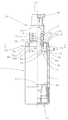
本発明に係る容器は、容器体2と、底蓋12と、摺動底板14と、吐出機構20と、スライド部材32と、回転筒50とで形成されている。
The container according to the present invention is formed by the
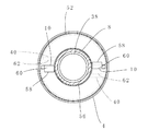
容器体2は、下面開口の円筒形の筒体4上端から内向きフランジ状の肩部6を介して口頸部8を起立している。この口頸部の上部外面には後述の装着筒を固定するためのネジ部が形成され、また、口頸部の下部外面には、後述の回転筒の抜止め手段9としての下向き段部が形成されている。上記肩部の左右両側には、図3に示すように半径方向の貫通孔10が穿設されている。
The
底蓋12は、蓋板の周縁から起立する嵌合筒を上記筒体4の下部外面に嵌合させている。
The
摺動底板14は、上記筒体の下部内に上方への摺動可能に嵌合させている。摺動底板の外縁部は上下2重のピストンに形成されており、これらピストンよりやや内側の底板部分は、上方から見て環状に隆起させて、後述受板の突上げ用凸部16としている。
The sliding
吐出機構20は、公知の事項であるために簡単に説明すると、上記口頸部8に嵌合された装着筒22の上端から、内向きフランジ状壁部を介してシリンダ24を垂下し、このシリンダ内に嵌合された筒状のピストンから上方付勢してステム26を起立し、このステムの上端にノズル30付き押下げヘッド28を付設している。上記シリンダ24と口頸部8との間には間隙を設ける。
Since the
スライド部材32は、円環状の受板34の外縁のシール部36を上記筒体4の上部内面に、また、上記受板34の内縁から起立したシール筒38の上端部を、上記口頸部8の内面に、それぞれ上昇可能かつ液密に嵌合させている。受板34の上面と肩部の下面の最下端部との間には上昇代hをとる。また、上記受板34の上面左右両部には半径方向に長いリブ状の係合突起40を形成している。
The
回転筒50は、筒壁52の下端を上記肩部6の上面外面に載置するとともに、その筒壁上端から内向きフランジ54を介して内筒56を垂下し、この内筒を口頸部8外面に回動可能に嵌合させている。口頸部への内筒の嵌合力は、筒体4へのシール部36への嵌合力と口頸部へのシール筒38の嵌合力との和よりも小さいものとする。これにより、受板からの押上げにより作動板が傾動するときに、シール部材は回転せず、回転筒だけが回転するように形成している。また、上記内向きフランジ54の内縁部は、上記抜止め手段9である、口頸部の下向き段部に係止されている。上記内向きフランジ54の左右両壁裏面からは、ヒンジ部58を介して作動板60をそれぞれ下方に突出している。これら作動板は図2に示すようにやや傾いた状態で貫通孔10を挿通する。図示例では、初期の傾斜角度を60度程度としている。各作動板60の下端部62を、上記係合突起40の周方向の同じ側面に係止させている。
The
さらに上記回動筒50の筒壁と筒体4の上部外面とにはそれぞれ第1マーク66a、第2マーク66bを描き、これら2つのマークで残量表示マーク66を形成する。第1マーク66aと第2マーク66bとの間には図1に示す如く周方向の回動代dを設け、摺動底板14が上限位置まで上昇したときに、第1、第2マークが上下方向に重なるようにしている。
Further, a
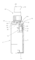
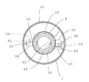
上記の構成において、図1の状態から押下げヘッド28を操作すると、容器体内の内容物がノズルから外方へ吐出されるとともに、摺動底板14が上昇する。摺動底板14がスライド部材の受板34下面まで達すると、突上げ用凸部16が受板34を突き上げ、これにより、各作動板60の下端部62が押し上げられる。この作動板の下端部62は係合突起40に係止されているために、作動板60は貫通孔の孔縁を支点として傾きながら斜め上外方へ押し出される。作動板60の上端部は回転筒50の内向きフランジ54を周方向斜上側へ押し上げようとするが、内向きフランジ54は抜止め手段9である下向き段部に係止している。その結果、貫通孔上方の作動板部分は図4に示すように撓みながら浅い角度で周方向の一方へ進出し、回転筒50を回転させる。そうすると回動筒の筒壁に描かれた第1マーク66aが第2マークの方に近づいていき、残量の減少が判る。摺動底板14が上限位置まで上昇すると、第1、第2マークが上下方向に重なり、残量がゼロになったことが判る。
In the above configuration, when the
図5は、本発明の実施例であり、シール筒の内面とシリンダ外面とに、回転規制手段42、44として相互に係合する回り止め用リブをそれぞれ縦設している。その構成は適宜変更することができ、例えば上記シール筒内面及びシリンダ外面に相互に係合する凹条及び凸条を形成してもよい。 FIG. 5 shows an embodiment of the present invention, in which anti-rotation ribs that engage with each other as rotation restricting means 42 and 44 are provided vertically on the inner surface and the outer surface of the cylinder. The configuration can be changed as appropriate, and for example, a concave line and a convex line that engage with the inner surface and the outer surface of the cylinder may be formed.
2…容器体 4…筒体 6…肩部 8…口頸部 9…抜止め手段 10…貫通孔
12…底蓋 14…摺動底板 16…突上げ用凸部
20…吐出機構 22…装着筒 24…シリンダ 26…ステム
28…押下げヘッド 30…ノズル
32…スライド部材 34…受板 36…シール部 38…シール筒
40…係合突起 42、44…回転規制手段
50…回転筒 52…筒壁 54…内向きフランジ 56…内筒
58…ヒンジ部 60…作動板 62…下端部
66…残量表示マーク 66a…第1マーク 66b…第2マーク
h…上昇代 d…回動代
DESCRIPTION OF
DESCRIPTION OF
DESCRIPTION OF
Claims (7)
上記口頸部から容器体内へシリンダを垂下するとともに、このシリンダ内から起立するステムの上部にノズル付きの押下げヘッドを付設し、
この押下げヘッドの上下動により、容器体内の内容物をシリンダへ吸い上げてノズルから吐出するとともに、容器体内の負圧化により摺動底板が上昇するように構成した摺動底板付き吐出容器において、
さらにシリンダ24外面と容器体2の筒体4上部内面との間隙内に、肩部6下面との間に上昇代hを存して嵌合させたリング状の受板34を含むスライド部材32と、
上記肩部6の上側に装着され、筒壁上端に内向きフランジ54を付設してなる回転筒50と、
肩部6を貫通して斜めに延びる少なくとも一つの作動板60とを含み、
この作動板60の両端部を上記受板34及び内向きフランジ54に連係させて、上記摺動底板14が上昇して受板34を押し上げたときに作動板60の傾動により回転筒50を傾動方向へ回転させるように形成し、
さらに回転筒50の回転に対応して内容物の使い終わりを予告する残量表示マーク66を少なくとも回転筒50に形成したことを特徴とする、摺動底板付き吐出容器。 A container body in which the neck and neck are erected from the upper end portion of the cylindrical body fitted with the sliding bottom plate so as to be movable up and down;
While hanging the cylinder from the mouth and neck into the container, a pressing head with a nozzle is attached to the top of the stem that stands up from the inside of the cylinder.
In the discharge container with a sliding bottom plate configured such that the vertical movement of the pressing head sucks up the contents in the container to the cylinder and discharges it from the nozzle, and the sliding bottom plate rises due to negative pressure in the container body,
Further, the slide member 32 includes a ring-shaped receiving plate 34 that is fitted in the gap between the outer surface of the cylinder 24 and the upper inner surface of the cylindrical body 4 of the container body 2 with the ascending margin h between the lower surface of the shoulder portion 6. When,
A rotating cylinder 50 mounted on the upper side of the shoulder 6 and having an inward flange 54 attached to the upper end of the cylinder wall;
At least one actuating plate 60 extending diagonally through the shoulder 6;
Both end portions of the operating plate 60 are linked to the receiving plate 34 and the inward flange 54, and the rotating cylinder 50 is tilted by the tilting of the operating plate 60 when the sliding bottom plate 14 rises and pushes up the receiving plate 34. Formed to rotate in the direction,
Furthermore, the discharge container with a sliding bottom plate is characterized in that a remaining amount display mark 66 for notifying the end of use of the contents corresponding to the rotation of the rotating cylinder 50 is formed on at least the rotating cylinder 50.
上記貫通孔60を、孔縁の一部で作動板60をスライド可能に支承するように設計したことを特徴とする、請求項2に記載の摺動底板付き吐出容器。 In the vicinity of the place where the rotating cylinder is installed, a retaining means 9 is provided above the rotating cylinder,
3. The discharge container with a sliding bottom plate according to claim 2, wherein the through hole 60 is designed so as to be slidably supported by a part of the hole edge.
Priority Applications (1)
| Application Number | Priority Date | Filing Date | Title |
|---|---|---|---|
| JP2008221780A JP5111304B2 (en) | 2008-08-29 | 2008-08-29 | Discharge container with sliding bottom plate |
Applications Claiming Priority (1)
| Application Number | Priority Date | Filing Date | Title |
|---|---|---|---|
| JP2008221780A JP5111304B2 (en) | 2008-08-29 | 2008-08-29 | Discharge container with sliding bottom plate |
Publications (2)
| Publication Number | Publication Date |
|---|---|
| JP2010052797A JP2010052797A (en) | 2010-03-11 |
| JP5111304B2 true JP5111304B2 (en) | 2013-01-09 |
Family
ID=42069140
Family Applications (1)
| Application Number | Title | Priority Date | Filing Date |
|---|---|---|---|
| JP2008221780A Expired - Fee Related JP5111304B2 (en) | 2008-08-29 | 2008-08-29 | Discharge container with sliding bottom plate |
Country Status (1)
| Country | Link |
|---|---|
| JP (1) | JP5111304B2 (en) |
Families Citing this family (1)
| Publication number | Priority date | Publication date | Assignee | Title |
|---|---|---|---|---|
| JP7053364B2 (en) * | 2018-04-27 | 2022-04-12 | 株式会社吉野工業所 | Injection container |
Family Cites Families (2)
| Publication number | Priority date | Publication date | Assignee | Title |
|---|---|---|---|---|
| JP2007119047A (en) * | 2005-10-31 | 2007-05-17 | Yoshino Kogyosho Co Ltd | Liquid spouting container |
| JP4864627B2 (en) * | 2006-09-29 | 2012-02-01 | 株式会社吉野工業所 | Container with pump |
-
2008
- 2008-08-29 JP JP2008221780A patent/JP5111304B2/en not_active Expired - Fee Related
Also Published As
| Publication number | Publication date |
|---|---|
| JP2010052797A (en) | 2010-03-11 |
Similar Documents
| Publication | Publication Date | Title |
|---|---|---|
| EP3162732A1 (en) | Refillable container | |
| CN215045212U (en) | Sealed lid and storing container | |
| CN215045213U (en) | Sealed lid and storing container | |
| JP5111304B2 (en) | Discharge container with sliding bottom plate | |
| JP6379011B2 (en) | Dropper container | |
| JP5661580B2 (en) | Double container | |
| JP4711293B2 (en) | Dispensing container | |
| JP6002361B2 (en) | Pouring cap | |
| JP2010274957A (en) | Metering and coating container | |
| JP5680981B2 (en) | cap | |
| JP5996290B2 (en) | cap | |
| JP2011093596A (en) | Tablet container | |
| JP5073405B2 (en) | Hinge cap | |
| CN110068198B (en) | Circular display structure for refrigerator | |
| JP7053364B2 (en) | Injection container | |
| JP5719615B2 (en) | Discharge member | |
| JP6298703B2 (en) | cap | |
| JP5897355B2 (en) | Cap with slit valve | |
| BR102012011648A2 (en) | CAN AND CAN INSPECTION WINDOW | |
| JP2018172168A (en) | Double container | |
| US12485442B2 (en) | Covered container for liquid cosmetic | |
| US831271A (en) | Closure device for jars, bottles, and similar vessels. | |
| JP4711292B2 (en) | Pumped bottom container. | |
| JP7321616B1 (en) | Containers with Lids and Lid Units | |
| RU104155U1 (en) | COOKING DEVICE |
Legal Events
| Date | Code | Title | Description |
|---|---|---|---|
| A621 | Written request for application examination |
Free format text: JAPANESE INTERMEDIATE CODE: A621 Effective date: 20110225 |
|
| A977 | Report on retrieval |
Free format text: JAPANESE INTERMEDIATE CODE: A971007 Effective date: 20120830 |
|
| TRDD | Decision of grant or rejection written | ||
| A01 | Written decision to grant a patent or to grant a registration (utility model) |
Free format text: JAPANESE INTERMEDIATE CODE: A01 Effective date: 20121003 |
|
| A01 | Written decision to grant a patent or to grant a registration (utility model) |
Free format text: JAPANESE INTERMEDIATE CODE: A01 |
|
| A61 | First payment of annual fees (during grant procedure) |
Free format text: JAPANESE INTERMEDIATE CODE: A61 Effective date: 20121009 |
|
| FPAY | Renewal fee payment (event date is renewal date of database) |
Free format text: PAYMENT UNTIL: 20151019 Year of fee payment: 3 |
|
| R150 | Certificate of patent or registration of utility model |
Ref document number: 5111304 Country of ref document: JP Free format text: JAPANESE INTERMEDIATE CODE: R150 Free format text: JAPANESE INTERMEDIATE CODE: R150 |
|
| LAPS | Cancellation because of no payment of annual fees |