JP5111349B2 - Modified hydrocarbon cation exchange membrane and method for producing the same - Google Patents
Modified hydrocarbon cation exchange membrane and method for producing the same Download PDFInfo
- Publication number
- JP5111349B2 JP5111349B2 JP2008316788A JP2008316788A JP5111349B2 JP 5111349 B2 JP5111349 B2 JP 5111349B2 JP 2008316788 A JP2008316788 A JP 2008316788A JP 2008316788 A JP2008316788 A JP 2008316788A JP 5111349 B2 JP5111349 B2 JP 5111349B2
- Authority
- JP
- Japan
- Prior art keywords
- cation exchange
- exchange membrane
- membrane
- ion
- hydrocarbon
- Prior art date
- Legal status (The legal status is an assumption and is not a legal conclusion. Google has not performed a legal analysis and makes no representation as to the accuracy of the status listed.)
- Expired - Fee Related
Links
Images

Classifications
-
- Y—GENERAL TAGGING OF NEW TECHNOLOGICAL DEVELOPMENTS; GENERAL TAGGING OF CROSS-SECTIONAL TECHNOLOGIES SPANNING OVER SEVERAL SECTIONS OF THE IPC; TECHNICAL SUBJECTS COVERED BY FORMER USPC CROSS-REFERENCE ART COLLECTIONS [XRACs] AND DIGESTS
- Y02—TECHNOLOGIES OR APPLICATIONS FOR MITIGATION OR ADAPTATION AGAINST CLIMATE CHANGE
- Y02E—REDUCTION OF GREENHOUSE GAS [GHG] EMISSIONS, RELATED TO ENERGY GENERATION, TRANSMISSION OR DISTRIBUTION
- Y02E60/00—Enabling technologies; Technologies with a potential or indirect contribution to GHG emissions mitigation
- Y02E60/30—Hydrogen technology
- Y02E60/50—Fuel cells
Landscapes
- Fuel Cell (AREA)
- Manufacture Of Macromolecular Shaped Articles (AREA)
Description
本発明は、改質炭化水素系陽イオン交換膜およびその製造方法に関し、詳しくは液体メタノール等を燃料とする直接液体燃料型燃料電池の隔膜に好適に用いられる改質炭化水素系陽イオン交換膜およびその製造方法に関する。特に、膜の表面領域が高度にイオンコンプレックス化され、メタノールクロスオーバー現象を抑制しつつ、高いプロトン伝導性を示す改質陽イオン交換膜およびその製造方法に関する。 The present invention relates to a modified hydrocarbon-based cation exchange membrane and a method for producing the same, and more particularly, to a modified hydrocarbon-based cation exchange membrane suitably used for a diaphragm of a direct liquid fuel type fuel cell using liquid methanol or the like as a fuel. And a manufacturing method thereof. In particular, the present invention relates to a modified cation exchange membrane and a method for producing the same, wherein the surface region of the membrane is highly ion-complexed and suppresses the methanol crossover phenomenon and exhibits high proton conductivity.
燃料電池は、燃料と酸化剤とを連続的に供給し、これらが反応したときの化学エネルギーを電力として取り出す発電システムである。燃料電池は、これに用いる電解質の種類によって、動作温度が比較的低いアルカリ型、リン酸型、固体高分子電解質型と、高温で動作する溶融炭酸塩型、固体酸化物電解質型とに大別される。 A fuel cell is a power generation system that continuously supplies fuel and an oxidant and extracts chemical energy as electric power when they react. Fuel cells are roughly classified into alkaline, phosphoric acid, and solid polymer electrolyte types that operate at relatively low temperatures, and molten carbonate and solid oxide electrolyte types that operate at high temperatures, depending on the type of electrolyte used. Is done.
これらの中で、固体高分子電解質型燃料電池は、固体高分子電解質として作用する隔膜の両面に、触媒が担持された拡散電極を接合し、一方の拡散電極が存在する側の室(以下、燃料室という)に燃料である水素を、他方のガス拡散電極が存在する側の室(以下、酸化剤室という)に酸化剤である酸素や空気等の酸素含有ガスをそれぞれ供給し、両ガス拡散電極間に外部負荷回路を接続することにより、燃料電池として作用させる。 Among these, the solid polymer electrolyte fuel cell has a diffusion electrode carrying a catalyst bonded to both sides of a diaphragm acting as a solid polymer electrolyte, and a chamber on the side where one diffusion electrode exists (hereinafter, Hydrogen, which is a fuel, is supplied to a fuel chamber), and an oxygen-containing gas, such as oxygen or air, which is an oxidizer, is supplied to a chamber (hereinafter referred to as an oxidizer chamber) where the other gas diffusion electrode exists. By connecting an external load circuit between the diffusion electrodes, it acts as a fuel cell.
こうした固体高分子電解質型燃料電池の基本構造を図1に示す。図中、(1)は電池隔膜、(2)は燃料流通孔、(3)は酸化剤ガス流通孔、(4)は燃料室側拡散電極、(5)は酸化剤室側ガス拡散電極、(6)は固体高分子電解質を示す。この固体高分子電解質型燃料電池において、燃料室(7)では、供給された水素ガスからプロトン(水素イオン)と電子が生成し、このプロトンは固体高分子電解質(6)内を伝導し、他方の酸化剤室(8)に移動し、空気又は酸素ガス中の酸素と反応して水を生成する。この時、燃料室側拡散電極(4)で生成した電子が、外部負荷回路を通じて酸化剤室側ガス拡散電極(5)へと移動することにより電気エネルギーが得られる。 The basic structure of such a solid polymer electrolyte fuel cell is shown in FIG. In the figure, (1) is a cell membrane, (2) is a fuel flow hole, (3) is an oxidant gas flow hole, (4) is a fuel chamber side diffusion electrode, (5) is an oxidant chamber side gas diffusion electrode, (6) indicates a solid polymer electrolyte. In this solid polymer electrolyte fuel cell, in the fuel chamber (7), protons (hydrogen ions) and electrons are generated from the supplied hydrogen gas, and the protons conduct in the solid polymer electrolyte (6), while It moves to the oxidant chamber (8) and reacts with oxygen in the air or oxygen gas to produce water. At this time, electric energy is obtained by electrons generated in the fuel chamber side diffusion electrode (4) moving to the oxidant chamber side gas diffusion electrode (5) through the external load circuit.
このような構造の固体高分子電解質型燃料電池において、通常使用されている燃料である水素が常温常圧で気体であり、その取り扱いが容易でないという理由から、燃料として水素に代えてメタノール、エタノール等を用いる直接液体燃料型燃料電池の開発が進められている。 In the solid polymer electrolyte fuel cell having such a structure, hydrogen, which is a commonly used fuel, is a gas at normal temperature and pressure, and is not easy to handle. Development of a direct liquid fuel type fuel cell using the above is progressing.
直接液体燃料型燃料電池の隔膜の電解質膜としては、通常、陽イオン交換膜が使用される。そして、この陽イオン交換膜には、燃料であるメタノール等の透過性が低いこと、電気抵抗が小さいこと、保水性が高いこと、長期の使用に対して安定であること、物理的な強度が強いことなどが要求される。 As the electrolyte membrane of the diaphragm of the direct liquid fuel type fuel cell, a cation exchange membrane is usually used. This cation exchange membrane has low permeability such as methanol as a fuel, low electrical resistance, high water retention, stability for long-term use, and physical strength. Strong things are required.
従来、固体高分子電解質型燃料電池用隔膜として使用される陽イオン交換膜としては、パーフルオロカーボンスルホン酸膜が主に使用されている。しかし、この膜は、メタノール等の透過性が高く、酸化剤室側ガス拡散電極に達したメタノール等がその表面で酸素または空気と反応するために過電圧が増大し、出力電圧が低下するという問題があった。この現象は、「メタノールクロスオーバー」と呼ばれている。 Conventionally, as a cation exchange membrane used as a membrane for a solid polymer electrolyte fuel cell, a perfluorocarbon sulfonic acid membrane has been mainly used. However, this membrane is highly permeable to methanol, etc., and the methanol etc. that reaches the oxidant chamber side gas diffusion electrode reacts with oxygen or air on its surface, so the overvoltage increases and the output voltage decreases. was there. This phenomenon is called “methanol crossover”.
これらの問題を克服するため、パーフルオロカーボンスルホン酸のような含フッ素重合体ではなく、炭化水素系重合体を母材とする陽イオン交換膜が種々検討されている。例えば、ポリオレフィン系やフッ素系樹脂製多孔質膜を基材として使用し、この基材に、陽イオン交換基を導入可能な官能基を有する単量体を特定の手法により含浸させ、次いで前記含浸させた単量体を重合させた後、得られた重合体に陽イオン交換基を導入する方法が提唱されている(特許文献1、特許文献2)。これらの文献には、この方法により、電気抵抗が小さく、水素ガスの透過性が小さい陽イオン交換膜が得られることが記載されている。
In order to overcome these problems, various cation exchange membranes based on a hydrocarbon-based polymer instead of a fluoropolymer such as perfluorocarbon sulfonic acid have been studied. For example, a polyolefin-based or fluororesin porous membrane is used as a base material, and the base material is impregnated with a monomer having a functional group capable of introducing a cation exchange group by a specific method, and then the impregnation is performed. A method has been proposed in which a cation exchange group is introduced into the obtained polymer after polymerizing the monomer thus formed (
しかしながら、これらの方法で製造される陽イオン交換膜においても、直接メタノール型燃料電池用隔膜として用いた場合には、メタノールの透過性は十分に抑制されていない。その結果、燃料室側から酸化剤室側へメタノールが拡散し、電池性能が低下するという問題が残る。さらに、メタノールの透過性を抑制するため膜組成を変更すると、膜の電気抵抗が増大し、その結果電池出力が低下する問題が起こる。 However, even in the cation exchange membranes produced by these methods, the permeability of methanol is not sufficiently suppressed when used directly as a membrane for a methanol fuel cell. As a result, methanol is diffused from the fuel chamber side to the oxidant chamber side, and there remains a problem that the battery performance is degraded. Furthermore, if the membrane composition is changed to suppress methanol permeability, the electrical resistance of the membrane increases, resulting in a problem that the battery output decreases.
メタノールの透過性が低い燃料電池用の隔膜として、基材となっている多孔質膜面に、さらに無機フィラーとイオン交換樹脂からなる層を有するイオン交換膜が提案されている(特許文献3)。しかしながら、このイオン交換膜においても、メタノールの透過性は十分低減されていない。 An ion exchange membrane having a layer made of an inorganic filler and an ion exchange resin on a porous membrane surface serving as a base material has been proposed as a diaphragm for a fuel cell having low methanol permeability (Patent Document 3). . However, even in this ion exchange membrane, the permeability of methanol is not sufficiently reduced.
また、スルホン化ポリエーテルエーテルケトンなどの酸性基を分子内に有するポリマーと、ポリベンズイミダゾールなどの塩基性基を分子内に有するポリマーとを混合した、いわゆるポリイオンコンプレックス膜を直接メタノール型燃料電池用隔膜に用いる技術が報告されている(特許文献4)。従来、このポリイオンコンプレックス膜は水素ガスを燃料とする燃料電池の隔膜に利用することが検討されてきたものである。この報告によれば、前記隔膜は高いプロトン伝導性、高温安定性、低いメタノールの透過性を示すと記載されている。 In addition, a so-called polyion complex membrane, which is a mixture of a polymer having an acidic group such as sulfonated polyetheretherketone in the molecule and a polymer having a basic group such as polybenzimidazole in the molecule, is used for direct methanol fuel cells. The technique used for a diaphragm is reported (patent document 4). Conventionally, the use of this polyion complex membrane as a membrane for a fuel cell using hydrogen gas as a fuel has been studied. According to this report, the diaphragm is described as exhibiting high proton conductivity, high temperature stability, and low methanol permeability.
本発明者らの検討によれば、上記隔膜は、確かに、それぞれ単独のポリマーからなる隔膜に比べればメタノールに対する膨潤安定性の改善効果やメタノール透過性の低減効果はある程度認められる。しかし、この隔膜は共有結合による架橋を有さない、いわゆる非架橋膜であるため、依然として、メタノール透過性の低減に関しては十分満足できるものではないことが明らかとなっている。 According to the study by the present inventors, the above-mentioned diaphragm surely has an effect of improving the swelling stability against methanol and the effect of reducing methanol permeability to some extent as compared with a diaphragm made of a single polymer. However, since this membrane is a so-called non-crosslinked membrane that does not have a covalent bond, it has been found that it is still not satisfactory in terms of reducing methanol permeability.
さらに、上記のポリイオンコンプレックス膜の製造に際し、酸性基含有ポリマーと塩基性基含有ポリマーを混合する必要があるが、この際に沈殿が生じる。この問題を避けるため、上記方法においては、一旦上記両ポリマーの混合液を塩基性にして製膜し、その後得られた膜に酸処理を施している。しかし、この方法は煩雑である。 Furthermore, in the production of the above-described polyion complex membrane, it is necessary to mix the acidic group-containing polymer and the basic group-containing polymer, and precipitation occurs at this time. In order to avoid this problem, in the above method, the mixed solution of the two polymers is once made basic, and then the resulting film is subjected to acid treatment. However, this method is complicated.
イオンコンプレックスが形成されてなる改質炭化水素系陽イオン交換膜を得る手段として、架橋型陽イオン交換樹脂が多孔質膜に充填されてなるイオン交換原膜に、陰イオン交換基を有する比較的低分子量の重合性単量体を浸透させ、ついで浸透させた重合性単量体を重合させる方法が提案されている(特許文献5)。この方法によれば、陽イオン交換膜中の全域にイオンコンプレックスが高率で形成されるため、メタノール透過性を顕著に低減できる。しかし、特許文献5に記載の陽イオン交換膜でもプロトン伝導性は必ずしも満足できるレベルではない。
As a means for obtaining a modified hydrocarbon-based cation exchange membrane formed with an ion complex, an ion exchange original membrane formed by filling a porous membrane with a crosslinked cation exchange resin has a relatively anion exchange group. A method has been proposed in which a low molecular weight polymerizable monomer is permeated and then the permeated polymerizable monomer is polymerized (Patent Document 5). According to this method, since the ion complex is formed at a high rate throughout the cation exchange membrane, methanol permeability can be significantly reduced. However, even in the cation exchange membrane described in
また、特に高温低湿状態でのプロトン伝導性を改善する技術として、特許文献6が提案されている。特許文献6には、酸性または塩基性部位を持つ主ポリマーに、主ポリマーと共に酸/塩基複合構造を作ることが可能な副ポリマーを、主ポリマーの酸性または塩基性部位以外の部位に対して多く導入してなる固体高分子電解質膜が開示されている。しかし、この固体高分子電解質膜では、主ポリマーと副ポリマーとが膜全体に均一に分散した構造であるため、前記特許文献5と同様に、プロトン伝導性の向上と、メタノール透過性の低減とは両立し難い。
プロトン伝導性を維持しつつ、メタノール透過性を低減する技術として、特許文献7が提案されている。特許文献7では、電解質膜表面の導電性を、膜内部の導電性よりも低く設定することを特徴としている。電解質膜表面の伝導性を低下する手段として、特許文献9では、(1)電解質膜表面に電子線を照射し膜表面を改変すること、あるいは(2)高イオン伝導膜表面に、低メタノール透過性、低イオン伝導性の膜を設けることが提案されている。
しかし、(1)の手法は、膜自体が損傷を受け、膜強度が低下する。また、(2)の手法では、燃料に対する寸法変化率が大きく異なる場合には膜同士の接着強度が充分ではないなどの問題があり、取りうる組合せに制限が生じる結果、隔膜性能の制御にも制限が生じる。 However, in the method (1), the film itself is damaged and the film strength is lowered. In addition, in the method (2), when the dimensional change rate with respect to the fuel is greatly different, there is a problem that the adhesive strength between the membranes is not sufficient. Limits arise.
このように、炭化水素系陽イオン交換膜において、直接液体燃料型燃料電池の隔膜として用いた場合に、プロトン伝導性を損なわずにメタノール透過性が低減されたものは知られていなかった。本発明はこのような従来技術の問題点に鑑みてなされたものであって、プロトン伝導性がほぼ維持され、かつメタノール透過性の低減された改質炭化水素系陽イオン交換膜およびその製造方法を提供することを目的としている。 Thus, it has not been known that a hydrocarbon cation exchange membrane has reduced methanol permeability without impairing proton conductivity when used as a diaphragm for a direct liquid fuel type fuel cell. The present invention has been made in view of such problems of the prior art, and is a modified hydrocarbon-based cation exchange membrane in which proton conductivity is substantially maintained and methanol permeability is reduced, and a method for producing the same The purpose is to provide.
本発明者は、上記課題に鑑み、鋭意研究を行ってきた。その結果、特定の構造を有する膜とすることで上記課題を解決できることを見出し、本発明を完成するに至った。 The present inventor has conducted intensive research in view of the above problems. As a result, the inventors have found that the above problem can be solved by using a film having a specific structure, and have completed the present invention.
すなわち、本発明は、架橋された炭化水素系陽イオン交換膜の少なくとも片面に、ジハロゲノアルカンにより架橋されたポリアミン含有層が形成されてなる改質炭化水素系陽イオン交換膜であって、該改質炭化水素系陽イオン交換膜中のイオン交換可能な陽イオンをCsイオンにイオン交換し、イオン交換後の膜の厚み方向におけるCsイオンの積算強度をX線マイクロアナライザ分析により算出し、該改質炭化水素系陽イオン交換膜の全厚(T)とした際に、該改質炭化水素系陽イオン交換膜の少なくとも片面の表面から深さ0.3Tまでの領域におけるCsイオン積算強度(Cs0.3)と、該表面からの深さ0.5Tまでの領域におけるCsイオン積算強度(Cs0.5)との比(Cs0.3/Cs0.5)が0.05〜0.50であることを特徴とする改質炭化水素系陽イオン交換膜、架橋された炭化水素系陽イオン交換膜の少なくとも片面に、重量平均分子量700〜8000のポリアミンを含浸し、該ポリアミンをジハロゲノアルカンで架橋する工程を含む該改質炭化水素系陽イオン交換膜の製造方法、および該改質炭化水素系陽イオン交換膜を用いることを特徴とする直接液体燃料型燃料電池である。 That is, the present invention is a modified hydrocarbon cation exchange membrane in which a polyamine-containing layer crosslinked with a dihalogenoalkane is formed on at least one surface of a crosslinked hydrocarbon cation exchange membrane, The ion-exchangeable cation in the modified hydrocarbon cation exchange membrane is ion-exchanged to Cs ion, and the integrated intensity of Cs ion in the thickness direction of the membrane after ion exchange is calculated by X-ray microanalyzer analysis, When the total thickness (T) of the modified hydrocarbon cation exchange membrane is used, the integrated Cs ion intensity in the region from the surface of at least one side of the modified hydrocarbon cation exchange membrane to a depth of 0.3 T ( Cs 0.3 ) and the ratio (Cs 0.3 / Cs 0.5 ) of Cs ion accumulated intensity (Cs 0.5 ) in the region up to a depth of 0.5 T from the surface is 0.05-0. .5 At least one surface of the modified hydrocarbon cation exchange membrane or the crosslinked hydrocarbon cation exchange membrane is impregnated with a polyamine having a weight average molecular weight of 700 to 8000, and the polyamine is dihalogenoalkane. A method for producing the modified hydrocarbon-based cation exchange membrane including a step of crosslinking with a direct liquid fuel type fuel cell using the modified hydrocarbon-based cation exchange membrane.
本発明によれば、プロトン伝導性がほぼ維持され、かつメタノール透過性が低減された改質炭化水素系陽イオン交換膜が提供される。この改質炭化水素系陽イオン交換膜は、膜の表面領域が高度にイオンコンプレックス化され、メタノールクロスオーバー現象を効果的に抑制しつつ、膜面方向および膜厚方向に対し高いプロトン伝導性を示す。したがって、このような改質炭化水素系陽イオン交換膜は、特に液体メタノール、液体エタノール等を燃料とした直接液体燃料型燃料電池用の隔膜として好ましく用いられる。 According to the present invention, there is provided a modified hydrocarbon cation exchange membrane in which proton conductivity is substantially maintained and methanol permeability is reduced. This modified hydrocarbon-based cation exchange membrane has a high ion conductivity in the membrane surface direction and the film thickness direction while the surface area of the membrane is highly ion-complexed, effectively suppressing the methanol crossover phenomenon. Show. Accordingly, such a modified hydrocarbon-based cation exchange membrane is preferably used as a diaphragm for a direct liquid fuel type fuel cell using, in particular, liquid methanol, liquid ethanol or the like as fuel.
以下、本発明について、その最良の形態を含めてさらに詳細に説明する。 Hereinafter, the present invention will be described in detail including the best mode.
本発明に係る改質炭化水素系陽イオン交換膜は、架橋された炭化水素系陽イオン交換膜の少なくとも片面に、ジハロゲノアルカンにより架橋されたポリアミン含有層が形成されてなる改質炭化水素系陽イオン交換膜であって、該改質炭化水素系陽イオン交換膜中のイオン交換可能な陽イオンをCsイオンにイオン交換し、イオン交換後の膜の厚み方向におけるCsイオンの積算強度をX線マイクロアナライザ分析により算出し、該改質炭化水素系陽イオン交換膜の全厚(T)とした際に、該改質炭化水素系陽イオン交換膜の少なくとも片面の表面から深さ0.3Tまでの領域におけるCsイオン積算強度(Cs0.3)と、該表面からの深さ0.5Tまでの領域におけるCsイオン積算強度(Cs0.5)との比(Cs0.3/Cs0.5)が0.05〜0.50である改質炭化水素系陽イオン交換膜である。
(改質炭化水素系陽イオン交換膜)
かかる改質炭化水素系陽イオン交換膜は、後述する架橋された炭化水素系陽イオン交換膜の少なくとも片面に、ジハロゲノアルカンにより架橋されたポリアミン含有層(後述)を有するものであれば、如何なる構造の炭化水素系陽イオン交換膜であっても良い。
The modified hydrocarbon cation exchange membrane according to the present invention is a modified hydrocarbon cation exchange membrane in which a polyamine-containing layer crosslinked with a dihalogenoalkane is formed on at least one surface of a crosslinked hydrocarbon cation exchange membrane. A cation exchange membrane, in which the ion-exchangeable cation in the modified hydrocarbon-based cation exchange membrane is exchanged with Cs ions, and the integrated intensity of Cs ions in the thickness direction of the membrane after ion exchange is expressed as X When the total thickness (T) of the modified hydrocarbon-based cation exchange membrane is calculated by a line microanalyzer analysis, the depth is 0.3T from the surface of at least one side of the modified hydrocarbon-based cation exchange membrane. The ratio (Cs 0.3 / Cs 0 ) of the Cs ion integrated intensity (Cs 0.3 ) in the region up to and the Cs ion integrated intensity (Cs 0.5 ) in the region up to a depth of 0.5 T from the surface . 5 ) A modified hydrocarbon cation exchange membrane having a value of 0.05 to 0.50.
(Modified hydrocarbon cation exchange membrane)
The modified hydrocarbon cation exchange membrane is not particularly limited as long as it has a polyamine-containing layer (described later) crosslinked with a dihalogenoalkane on at least one surface of a crosslinked hydrocarbon cation exchange membrane described later. It may be a hydrocarbon-based cation exchange membrane having a structure.
すなわち、ジハロゲノアルカンにより架橋されたポリアミン含有層は、架橋された炭化水素系陽イオン交換膜の片面のみに存在しても、両面に存在しても良い。通常、ジハロゲノアルカンにより架橋されたポリアミン含有層は、架橋された炭化水素系陽イオン交換膜の両面に形成されてなる。更にはこれらの層は架橋された炭化水素系陽イオン交換膜の内部に存在しても、該陽イオン交換膜の外部に存在しても、両者にまたがって存在しても良い。 That is, the polyamine-containing layer crosslinked with a dihalogenoalkane may be present only on one side of the crosslinked hydrocarbon cation exchange membrane or on both sides. Usually, the polyamine-containing layer crosslinked with a dihalogenoalkane is formed on both surfaces of a crosslinked hydrocarbon-based cation exchange membrane. Furthermore, these layers may exist inside the crosslinked hydrocarbon cation exchange membrane, may exist outside the cation exchange membrane, or may exist over both.
これらの層は、少なくともその一部、好ましくは全部が、架橋された炭化水素系陽イオン交換膜の内部に存在していることが好ましい。ジハロゲノアルカンにより架橋されたポリアミン含有層が架橋された炭化水素系陽イオン交換膜の内部に存在することで、本発明における高い燃料クロスオーバー抑制効果を得ることが可能になる。 It is preferable that at least a part, preferably all, of these layers exist inside the crosslinked hydrocarbon cation exchange membrane. The presence of the polyamine-containing layer crosslinked with the dihalogenoalkane inside the crosslinked hydrocarbon cation exchange membrane makes it possible to obtain the high fuel crossover suppression effect in the present invention.
本発明の改質炭化水素系陽イオン交換膜においては、ジハロゲノアルカンにより架橋されたポリアミン含有層が、架橋された炭化水素系陽イオン交換膜と、イオンコンプレックスを形成していると考えられる。ここで、イオンコンプレックスを形成するとは、母材である架橋された炭化水素系陽イオン交換膜中の陽イオン交換基が、ポリアミンが有するアミノ基類により中和された状態を指し、該陽イオン交換基が、プロトンやナトリウムイオンなどの自由にイオン交換される低分子量の対イオンとイオン対を形成した状態とは区別される。 In the modified hydrocarbon cation exchange membrane of the present invention, the polyamine-containing layer crosslinked with a dihalogenoalkane is considered to form an ion complex with the crosslinked hydrocarbon cation exchange membrane. Here, forming an ion complex refers to a state in which the cation exchange group in the crosslinked hydrocarbon-based cation exchange membrane as a base material is neutralized by amino groups of the polyamine, and the cation It is distinguished from the state in which the exchange group forms an ion pair with a low molecular weight counter ion such as proton or sodium ion which is freely ion-exchanged.
更に、改質炭化水素系陽イオン交換膜の少なくとも片面における表面領域の方が、該膜の中心領域よりも高度にイオンコンプレックス化されてなることが必要である。なお、膜の両表面に高度にイオンコンプレックス化された領域が形成されていてもよい。 Furthermore, it is necessary that the surface region on at least one surface of the modified hydrocarbon cation exchange membrane is made higher in ion complex than the central region of the membrane. Note that highly ion-complexed regions may be formed on both surfaces of the film.
膜の表面領域の方が中心領域よりも高度にイオンコンプレックス化されている場合、該表面領域によりメタノールなどの燃料透過を抑制する効果が発現する一方、膜の中心領域でのイオンコンプレックス化の程度は低いため、母材膜が有するプロトン伝導性がほぼ維持されると考えられる。すなわち、膜の少なくとも片面における表面領域の方が、該膜の中心領域よりも高度にイオンコンプレックス化されてなることにより、メタノールクロスオーバー現象を効果的に抑制しつつ、高いプロトン伝導性を示すという本発明の効果が発現されると考えられる。 When the surface region of the membrane is highly ion complexed than the central region, the surface region has an effect of suppressing the permeation of fuel such as methanol, while the degree of ion complexation in the central region of the membrane Therefore, it is considered that the proton conductivity of the base material film is almost maintained. That is, the surface region on at least one side of the membrane is highly ion-complexed than the central region of the membrane, and thus exhibits high proton conductivity while effectively suppressing the methanol crossover phenomenon. It is considered that the effect of the present invention is exhibited.
なお、本発明の改質炭化水素系陽イオン交換膜において、母材である架橋された炭化水素系陽イオン交換膜の陽イオン交換基が、ジハロゲノアルカンで架橋されたポリアミン含有層中のポリアミンが有するアミノ基類とイオンコンプレックスを形成した場合、該陽イオン交換基は低分子量のカチオンと自由にイオン交換することが困難になる。一方、前記陽イオン交換膜の陽イオン交換基のうちイオンコンプレックスを形成していないものは、低分子量のカチオンと自由にイオン交換が可能である。 In the modified hydrocarbon cation exchange membrane of the present invention, the polyamine in the polyamine-containing layer in which the cation exchange group of the crosslinked hydrocarbon cation exchange membrane as a base material is crosslinked with a dihalogenoalkane is used. When an ion complex is formed with the amino groups possessed by the cation, it becomes difficult to freely ion-exchange the cation exchange group with a low molecular weight cation. On the other hand, those which do not form an ion complex among the cation exchange groups of the cation exchange membrane can freely exchange ions with low molecular weight cations.
したがって、イオンコンプレックス化された陽イオン交換基と、イオンコンプレックスを形成していない陽イオン交換基の分布状態は以下の方法により測定することができ、該方法により膜中のイオンコンプレックス化の程度を評価できる。 Therefore, the distribution state of the ion-complexed cation exchange group and the cation-exchange group not forming the ion complex can be measured by the following method, and the degree of ion complexation in the membrane can be measured by this method. Can be evaluated.
本発明では、改質炭化水素系陽イオン交換膜中のイオン交換可能な陽イオンをCs(セシウム)にイオン交換し、イオン交換後の膜の厚み方向におけるCsイオンの積算強度をX線マイクロアナライザ分析(EPMA)により測定することで、イオンコンプレックス化されたイオン交換基の分布状態を評価する。 In the present invention, the ion-exchangeable cation in the modified hydrocarbon-based cation exchange membrane is ion-exchanged to Cs (cesium), and the integrated intensity of Cs ions in the thickness direction of the membrane after the ion exchange is measured by an X-ray microanalyzer. By measuring by analysis (EPMA), the distribution state of ion-exchange groups ion-complexed is evaluated.
イオンコンプレックス化された陽イオン交換基ではCsへのイオン交換が行われず、一方イオンコンプレックス化されていない陽イオン交換基ではCsへのイオン交換が行われるため、Csの分布が少ない領域が、より高度にイオンコンプレックス化された領域を示す。 In the ion-complexed cation exchange group, ion exchange to Cs is not performed. On the other hand, in the cation-exchange group not ion-complexed, ion exchange to Cs is performed. A highly ion-complexed region is shown.
Csイオン交換後の膜について、膜表面の比較的浅い領域におけるCsイオン積算強度と、膜表面から中心部に至る領域のCsイオン積算強度を対比することで、膜の厚み方向でのイオンコンプレックス化領域の分布状態を確認できる。 Concerning the membrane after Cs ion exchange, by comparing the Cs ion integrated intensity in the relatively shallow region of the membrane surface with the Cs ion integrated intensity in the region from the membrane surface to the center, ion complexization in the thickness direction of the membrane The distribution state of the area can be confirmed.
本明細書では、改質炭化水素系陽イオン交換膜の全厚をTとし、Csイオン交換後の膜について、膜表面から深さ0.3Tまでの領域におけるCsイオン積算強度(Cs0.3)と、該表面から深さ0.5Tまでの領域におけるCsイオン積算強度(Cs0.5)との比(Cs0.3/Cs0.5)に基づいて、イオンコンプレックス化領域の分布状態を評価する。 In this specification, the total thickness of the modified hydrocarbon-based cation exchange membrane is T, and the Cs ion accumulated intensity (Cs 0.3) in the region from the membrane surface to a depth of 0.3 T is assumed for the membrane after Cs ion exchange. ) And the ratio (Cs 0.3 / Cs 0.5 ) of the integrated Cs ion intensity (Cs 0.5 ) in the region from the surface to a depth of 0.5 T (Cs 0.3 / Cs 0.5 ) To evaluate.
ちなみに、イオンコンプレックス化されていない架橋された炭化水素系陽イオン交換膜(以下、未処理膜という)では、膜中のすべての陽イオン交換基が陽イオン交換能を有するため、すべての陽イオン交換基のカチオンがCsにイオン交換される。したがって、Csイオンは膜全体に均一に分散する。このため、Cs0.3/Cs0.5は、測定領域の面積にほぼ等しく、0.3/0.5であり、約0.6となる。 Incidentally, in a crosslinked hydrocarbon-based cation exchange membrane (hereinafter referred to as an untreated membrane) that is not ion-complexed, all cation exchange groups in the membrane have a cation exchange capacity, so all cations The cation of the exchange group is ion exchanged to Cs. Therefore, Cs ions are uniformly dispersed throughout the film. For this reason, Cs 0.3 / Cs 0.5 is substantially equal to the area of the measurement region, and is 0.3 / 0.5, which is about 0.6.
一方、改質炭化水素系陽イオン交換膜の少なくとも片面における表面領域の方が、該膜の中心領域よりも高度にイオンコンプレックス化されている場合には、Csイオン交換後の膜においては、膜表面から深さ0.3Tまでの領域におけるCsイオン積算強度(Cs0.3)が、未処理膜よりも顕著に低下する。一方、膜の中心領域は、イオンコンプレックス化されず、活性を維持するイオン交換基が表面領域よりも多量に存在するので、膜表面から深さ0.5Tまでの領域におけるCsイオン積算強度(Cs0.5)は未処理膜よりは低下するものの、Cs0.3の低下の度合いほどには低下しない。 On the other hand, when the surface region on at least one surface of the modified hydrocarbon-based cation exchange membrane is more highly ion-complexed than the center region of the membrane, the membrane after Cs ion exchange The integrated Cs ion intensity (Cs 0.3 ) in the region from the surface to a depth of 0.3 T is significantly lower than that of the untreated film. On the other hand, the central region of the membrane is not ion-complexed, and there are more ion-exchange groups that maintain activity than the surface region. Therefore, the Cs ion integrated intensity (Cs) in the region from the membrane surface to a depth of 0.5 T is present. 0.5 ) is lower than that of the untreated film, but not as low as the degree of decrease of Cs 0.3 .
したがって、表面領域が高度にイオンコンプレックス化された改質炭化水素系陽イオン交換膜では、0.6よりも小さくなる。 Therefore, the modified hydrocarbon cation exchange membrane whose surface region is highly ion-complexed is smaller than 0.6.
なお、改質炭化水素系陽イオン交換膜において、膜の表面領域と中心領域が均一にイオンコンプレックス化されている場合には、Cs0.5とCs0.3の低下度合いは等しくなるため、Cs0.3/Cs0.5はやはり0.6となる。 In the modified hydrocarbon cation exchange membrane, when the surface region and the central region of the membrane are uniformly ion-complexed, the degree of decrease in Cs 0.5 and Cs 0.3 is equal, Cs 0.3 / Cs 0.5 is also 0.6.
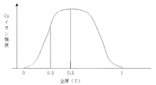
図2に、膜の少なくとも片面における表面領域の方が、該膜の中心領域よりも高度にイオンコンプレックス化された場合の、Csイオン交換後の改質炭化水素系陽イオン交換膜についてのEPMA分析によるCsイオン強度スペクトルの典型例を示す。図2の曲線は、所定の深さにおけるCsイオン強度を示す。したがって、膜表面から深さ0.3Tまでの領域におけるCsイオン積算強度(Cs0.3)は、該曲線とX軸と0.3Tにおける垂線とで囲まれる面積を示す。同様に膜表面から深さ0.5Tまでの領域におけるCsイオン積算強度(Cs0.5)は、該曲線とX軸と0.5Tにおける垂線とで囲まれる面積を示す。 FIG. 2 shows an EPMA analysis of a modified hydrocarbon-based cation exchange membrane after Cs ion exchange when the surface region on at least one side of the membrane is more highly ion-complexed than the central region of the membrane. Shows a typical example of the Cs ion intensity spectrum by. The curve in FIG. 2 shows the Cs ionic strength at a given depth. Therefore, the Cs ion integrated intensity (Cs 0.3 ) in the region from the film surface to a depth of 0.3 T indicates an area surrounded by the curve, the X axis, and a perpendicular line at 0.3 T. Similarly, the Cs ion integrated intensity (Cs 0.5 ) in the region from the film surface to a depth of 0.5 T indicates an area surrounded by the curve, the X axis, and a perpendicular line at 0.5 T.
本発明の改質炭化水素系陽イオン交換膜においては、Csイオン交換後の膜について、Cs0.3/Cs0.5が0.05〜0.50である。Cs0.3/Cs0.5が0.05未満では膜の中心近くまで高度にイオンコンプレックス化されているので、プロトン伝導性が低くなる。Cs0.3/Cs0.5が0.50を超えている場合には、膜表面の高度にイオンコンプレックス化された領域が浅く、メタノールクロスオーバー減少を抑制できなくなるか、あるいは、膜の中心領域と膜表面とのイオンコンプレックス化度合いに大差が無く、プロトン伝導性が低下する。 In the modified hydrocarbon cation exchange membrane of the present invention, Cs 0.3 / Cs 0.5 is 0.05 to 0.50 for the membrane after Cs ion exchange. When Cs 0.3 / Cs 0.5 is less than 0.05, proton conductivity is lowered because the ion complex is highly formed to the vicinity of the center of the membrane. When Cs 0.3 / Cs 0.5 exceeds 0.50, the highly ion-complexed region on the surface of the film is shallow, and the reduction in methanol crossover cannot be suppressed, or the center of the film There is no great difference in the degree of ion complexation between the region and the membrane surface, and proton conductivity is reduced.
Cs0.3/Cs0.5は好ましくは0.10〜0.40、さらに好ましくは0.20〜0.40の範囲である。 Cs 0.3 / Cs 0.5 is preferably in the range of 0.10 to 0.40, more preferably 0.20 to 0.40.
Cs0.3/Cs0.5は、後述する本発明の改質炭化水素系陽イオン交換膜の製造方法において、母材である架橋陽イオン交換膜へのポリアミンの含浸状態により制御できる。 Cs 0.3 / Cs 0.5 can be controlled by the impregnation state of the polyamine in the crosslinked cation exchange membrane as a base material in the method for producing a modified hydrocarbon cation exchange membrane of the present invention described later.
たとえば、比較的高分子量のポリアミンを用いると、膜の中心領域まではポリアミンが含浸されない。この結果、表面部分におけるCsイオン積算強度(Cs0.3)は低下するが、Cs0.5の低下の度合いは少ない。このため、Cs0.3/Cs0.5は小さくなる。一方、比較的低分子量のポリアミンを用いると、膜の中心領域まではポリアミンが含浸されやすくなり、Cs0.3の低下度合いと、Cs0.5の低下度合いには大差が無くなり、Cs0.3/Cs0.5は小さくならない。 For example, when a relatively high molecular weight polyamine is used, the polyamine is not impregnated up to the central region of the membrane. As a result, the Cs ion integrated intensity (Cs 0.3 ) in the surface portion is reduced, but the degree of decrease in Cs 0.5 is small. For this reason, Cs 0.3 / Cs 0.5 becomes small. On the other hand, when a relatively low molecular weight polyamine is used, the polyamine is easily impregnated up to the central region of the film, and there is no significant difference between the degree of reduction of Cs 0.3 and the degree of reduction of Cs 0.5 . 3 / Cs 0.5 does not become small.
なお、本発明の改質炭化水素系陽イオン交換膜において、ジハロゲノアルカンにより架橋されたポリアミン含有層が架橋された炭化水素系陽イオン交換膜とイオンコンプレックスを形成してなる改質炭化水素系陽イオン交換膜は、表面領域における陽イオン交換基がイオンコンプレックス化されたとしても、陽イオン交換基自体が消失しているわけではない。たとえば、陽イオン交換基がスルホン酸基(SO3 −)である場合、スルホン酸基はポリアミンの有するアミノ基類とイオンコンプレックスを形成することで中和されるが、スルホン酸基(SO3 −)自体は存在する。このスルホン酸基は隔膜中に均一に分散して存在する。 In the modified hydrocarbon-based cation exchange membrane of the present invention, a modified hydrocarbon-based membrane formed by forming an ion complex with a hydrocarbon-based cation exchange membrane in which a polyamine-containing layer crosslinked with a dihalogenoalkane is crosslinked. In the cation exchange membrane, even if the cation exchange group in the surface region is ion-complexed, the cation exchange group itself is not lost. For example, cation exchange groups are sulfonic acid group (SO 3 -) when it is, but the sulfonic acid groups are neutralized by forming an amino group such as ion complex with the polyamine, a sulfonic acid group (SO 3 - ) Itself exists. This sulfonic acid group exists uniformly dispersed in the diaphragm.
したがって、本発明の改質炭化水素系陽イオン交換膜において、膜の少なくとも片面における表面領域の方が、該膜の中心領域よりも高度にイオンコンプレックス化された場合であっても、陽イオン交換基のみに由来する元素(例えば、スルホン酸基では硫黄、リン酸基ではリン)の分布をEPMAで測定した場合には、陽イオン交換基自体は膜中に均一に分散していることが分かる。たとえば、陽イオン交換基が硫黄(S)の場合には、膜表面から深さ0.3Tまでの領域における硫黄の積算強度(S0.3)と、該表面から深さ0.5Tまでの領域における硫黄の積算強度(S0.5)との比(S0.3/S0.5)は、ほぼ0.6となる。 Therefore, in the modified hydrocarbon-based cation exchange membrane of the present invention, even when the surface region on at least one side of the membrane is more highly ion-complexed than the central region of the membrane, the cation exchange When the distribution of elements derived only from groups (for example, sulfur for sulfonic acid groups and phosphorus for phosphoric acid groups) is measured by EPMA, it can be seen that the cation exchange groups themselves are uniformly dispersed in the membrane. . For example, when the cation exchange group is sulfur (S), the cumulative intensity of sulfur (S 0.3 ) in the region from the membrane surface to a depth of 0.3 T, and the depth from the surface to 0.5 T The ratio (S 0.3 / S 0.5 ) to the cumulative intensity of sulfur (S 0.5 ) in the region is approximately 0.6.
上述のごとき構造を有する本発明の改質炭化水素系陽イオン交換膜は、通常、イオン交換容量が0.3〜4.5mmol/gであり、好ましくは0.5〜3mmol/gである。イオン交換容量が0.3mmol/g未満ではプロトン伝導性が不充分となり、また、4.5mmol/gを超える場合にはメタノールなどの燃料透過を抑制する効果が不充分となり好ましくない。 The modified hydrocarbon cation exchange membrane of the present invention having the structure as described above usually has an ion exchange capacity of 0.3 to 4.5 mmol / g, preferably 0.5 to 3 mmol / g. When the ion exchange capacity is less than 0.3 mmol / g, the proton conductivity is insufficient, and when it exceeds 4.5 mmol / g, the effect of suppressing the permeation of fuel such as methanol is insufficient.
また、本発明の改質炭化水素系陽イオン交換膜は、膜抵抗を小さくするために、特に直接液体型燃料電池用隔膜として用いる場合には乾燥によるプロトンの伝導性の低下が生じ難いように、含水率は5%以上、好適には8%以上であるのが好ましい。一般には含水率は5〜90%程度で保持される。 Also, the modified hydrocarbon cation exchange membrane of the present invention is less likely to cause a decrease in proton conductivity due to drying, particularly when used as a direct liquid fuel cell membrane to reduce membrane resistance. The water content is 5% or more, preferably 8% or more. Generally, the moisture content is maintained at about 5 to 90%.
さらに、本発明の改質炭化水素系陽イオン交換膜の膜厚は、膜抵抗を低く抑えるという観点及び支持膜として必要な機械的強度を付与するという観点から、通常、5〜150μmの厚みを有するものが好ましく、より好ましくは7〜90μmの厚みを有するものが望ましい。 Furthermore, the film thickness of the modified hydrocarbon cation exchange membrane of the present invention is usually 5 to 150 μm from the viewpoint of keeping the membrane resistance low and providing the mechanical strength necessary as a support membrane. What has is preferable, What has thickness of 7-90 micrometers more preferably is desirable.
本発明の改質炭化水素系陽イオン交換膜は、上記の構造や物性を有することにより、メタノールなどの燃料透過性を高度に抑制可能になり、例えば、25℃で該陽イオン交換膜の片面に30質量%のメタノール水溶液を接触させ、もう一方の面にアルゴンガスをフローさせて測定したメタノール透過率において、通常は500〜1000g/(m2・hr)であり、時には10〜500g/(m2・hr)のものまで得ることができる。後述の膜面方向のプロトン伝導性を高く保つことができ、高い燃料電池出力を得られる点では、メタノール透過率は100〜800g/(m2・hr)であることが好ましい。 The modified hydrocarbon-based cation exchange membrane of the present invention has the above-described structure and physical properties, so that the fuel permeability of methanol or the like can be highly suppressed. For example, at one side of the cation exchange membrane at 25 ° C. The methanol permeability measured by contacting a 30% by mass aqueous methanol solution with argon gas on the other side is usually 500 to 1000 g / (m 2 · hr), sometimes 10 to 500 g / ( m 2 · hr) can be obtained. The proton permeability in the membrane surface direction, which will be described later, can be kept high, and the methanol permeability is preferably 100 to 800 g / (m 2 · hr) in that a high fuel cell output can be obtained.
さらに、本発明の改質炭化水素系陽イオン交換膜は、上記のように極めて低いメタノール透過率を有しながら、一方で、高いプロトン伝導性を有するという特徴を有する。このため、本発明の改質炭化水素系陽イオン交換膜を直接液体燃料型燃料電池用隔膜として用いた場合には、電池の内部抵抗を低く抑えながら、メタノールなどの燃料クロスオーバーを有効に抑制できるため高い出力が得られ、極めて好適である。通常、上記のプロトン伝導性は膜面方向のプロトン伝導性であり、膜面上に複数個の白金線を配し、これら白金線間の交流インピーダンス測定により得られる膜面方向の膜抵抗の逆数(Sp)として表される。本発明の改質炭化水素系陽イオン交換膜では、このようにして求められるプロトン伝導性(Sp)は、40℃湿潤状態で、通常1〜40S・cm−2であり、特には30〜100S・cm−2のものまで得ることができる。前述のメタノール透過率を低く保つことができる点では、プロトン伝導性(Sp)は10〜50S・cm−2であることが好ましい。 Furthermore, the modified hydrocarbon-based cation exchange membrane of the present invention is characterized by having a high proton conductivity while having a very low methanol permeability as described above. For this reason, when the modified hydrocarbon cation exchange membrane of the present invention is used as a diaphragm for a direct liquid fuel type fuel cell, fuel crossover such as methanol is effectively suppressed while keeping the internal resistance of the cell low. Therefore, a high output can be obtained, which is very suitable. Usually, the proton conductivity is proton conductivity in the direction of the membrane surface, and a plurality of platinum wires are arranged on the membrane surface, and the inverse of the membrane resistance in the membrane surface direction obtained by measuring the AC impedance between these platinum wires. Expressed as (Sp). In the modified hydrocarbon cation exchange membrane of the present invention, the proton conductivity (Sp) thus determined is usually 1 to 40 S · cm −2 in a wet state at 40 ° C., particularly 30 to 100 S. -It can be obtained up to cm- 2 . The proton conductivity (Sp) is preferably 10 to 50 S · cm −2 in that the methanol permeability described above can be kept low.
また、陽イオン交換膜のプロトン伝導性は、例えば、硫酸水溶液中で定法により直接測定される膜厚方向の膜抵抗の逆数(St)でも評価可能である。本発明の改質炭化水素系陽イオン交換膜では、25℃で3mol/L−硫酸水溶液中で測定したプロトン伝導性(St)は、通常1〜40S・cm−2であり、特には30〜100S・cm−2のものまで得ることができる。一般に、陽イオン交換膜は、メタノール透過率を抑制する処理を施すなどした場合特に、上述の膜面方向の交流インピーダンス測定から求められるSpに比べて、直接に膜厚方向に測定したStが桁違いに小さくなることがあり、このため燃料電池用隔膜としては不適であることがある。これに対し、本発明の改質炭化水素系陽イオン交換膜では、詳細な理由は不明であるが、Spに対するStの低減の割合が、改質していない未処理膜の場合と概ね同等となる特徴を有する。従って、燃料電池用隔膜として用いた場合、高出力を得ることができ、好適である。
(改質炭化水素系陽イオン交換膜の製造方法)
本発明における上述した改質炭化水素系陽イオン交換膜は、架橋された炭化水素系イオン交換膜の少なくとも片面に、ジハロゲノアルカンにより架橋されたポリアミン含有層が形成されさえすれば、どのような製造方法によって製造されても構わない。
The proton conductivity of the cation exchange membrane can also be evaluated by, for example, the reciprocal number (St) of the membrane resistance in the film thickness direction measured directly in a sulfuric acid aqueous solution by an ordinary method. In the modified hydrocarbon cation exchange membrane of the present invention, the proton conductivity (St) measured in a 3 mol / L-sulfuric acid aqueous solution at 25 ° C. is usually 1 to 40 S · cm −2 , particularly 30 to Even 100 S · cm −2 can be obtained. In general, the cation exchange membrane has a St value measured directly in the film thickness direction as compared with the Sp obtained from the above-mentioned AC impedance measurement in the film surface direction, particularly when the treatment for suppressing the methanol permeability is performed. The difference may be small, which may make it unsuitable as a fuel cell membrane. In contrast, in the modified hydrocarbon-based cation exchange membrane of the present invention, the detailed reason is unknown, but the ratio of reduction of St to Sp is almost the same as that of the untreated membrane that has not been modified. It has the following characteristics. Accordingly, when used as a fuel cell membrane, high output can be obtained, which is preferable.
(Method for producing modified hydrocarbon cation exchange membrane)
The above-described modified hydrocarbon cation exchange membrane according to the present invention is not limited as long as a polyamine-containing layer crosslinked with a dihalogenoalkane is formed on at least one surface of the crosslinked hydrocarbon ion exchange membrane. You may manufacture with a manufacturing method.
上述した構造を簡便に形成でき、かつ、本発明の効果をより好適に発揮できる点で、以下の製造方法によることが好ましい。 The following production method is preferred in that the structure described above can be easily formed and the effects of the present invention can be more suitably exhibited.
すなわち、架橋された炭化水素系陽イオン交換膜の少なくとも片面に、重量平均分子量700〜8000のポリアミンを含浸し、該ポリアミンをジハロゲノアルカンで架橋する工程を含む製造方法である。
(ポリアミン)
本発明におけるポリアミンとは、一分子中に、少なくとも2個以上のアミノ基を有する高分子化合物のことをいい、該特徴を有する化合物であれば従来公知のどのような化合物であっても使用可能である。
That is, it is a production method including a step of impregnating a polyamine having a weight average molecular weight of 700 to 8000 on at least one surface of a crosslinked hydrocarbon cation exchange membrane and crosslinking the polyamine with a dihalogenoalkane.
(Polyamine)
The polyamine in the present invention means a polymer compound having at least two amino groups in one molecule, and any conventionally known compound can be used as long as it has such characteristics. It is.
該ポリアミンの分子中において、アミノ基の存在位置は特に限定されず、ポリアミンの主鎖中であっても、または主鎖から分岐した側鎖のいずれの位置に存在していても構わない。 In the polyamine molecule, the position of the amino group is not particularly limited, and the amino group may be present in the main chain of the polyamine or in any position of the side chain branched from the main chain.
ここで、該アミノ基としては、1〜3級アミノ基、第4級アンモニウム塩基、ピリジニウム基、第4級ピリジニウム塩基などが挙げられ、これらを単独であるいは複数種類の組み合わせで有していてもよい。中でも、アミノ基の化学的安定性の観点からは、1〜3級アミノ基や第4級アンモニウム塩基が好ましく、また、改質炭化水素系陽イオン交換膜内でイオンコンプレックスが安定して形成され、燃料クロスオーバーの低減効果が安定して持続するようにするためには、1〜3級アミノ基やピリジル基であることが好ましく、1〜3級アミノ基であることが最も好ましい。 Here, examples of the amino group include a primary to tertiary amino group, a quaternary ammonium base, a pyridinium group, and a quaternary pyridinium base, and these amino groups may be used alone or in combination of plural kinds. Good. Among these, from the viewpoint of chemical stability of the amino group, a primary to tertiary amino group or a quaternary ammonium base is preferable, and an ion complex is stably formed in the modified hydrocarbon cation exchange membrane. In order to stably maintain the effect of reducing the fuel crossover, it is preferably a primary to tertiary amino group or a pyridyl group, and most preferably a primary to tertiary amino group.
なお、前記アミノ基が、第4級アンモニウム塩基などのような正電荷を持つ場合、その対イオンは、塩素イオン、臭素イオン、よう素イオン等のハロゲンイオンや、硫酸イオン、炭酸イオン、硝酸イオンなどいずれのものであっても構わない。さらに、前記アミノ基は、アミノ基の窒素原子にプロトンが付加された、いわゆるプロトネーション型のものであっても構わない。この場合も、該プロトネーション型アミノ基の対イオンは、塩素イオン、臭素イオン、よう素イオン等のハロゲンイオンや、硫酸イオン、炭酸イオン、硝酸イオンなどのどのようなものでもよい。 When the amino group has a positive charge such as a quaternary ammonium base, the counter ion is a halogen ion such as a chlorine ion, a bromine ion or an iodine ion, a sulfate ion, a carbonate ion, or a nitrate ion. Any of these may be used. Furthermore, the amino group may be a so-called protonation type in which a proton is added to the nitrogen atom of the amino group. In this case as well, the counter ion of the protonation type amino group may be any halogen ion such as chlorine ion, bromine ion or iodine ion, sulfate ion, carbonate ion or nitrate ion.
また、本発明で用いられるポリアミンにおいて、前記アミノ基の内少なくとも2個は1〜3級アミノ基であることが好ましい。ここで、1〜3級アミノ基には、前記プロトネーション型のものを含む。少なくとも2個の1〜3級アミノ基を分子内に有することで、後述するジハロゲノアルカンによる架橋が可能となって、安定して燃料クロスオーバーの抑制効果が発現可能となる。これらの効果をより効果的に発現させるためには、本発明のポリアミンが有するアミノ基のうち1〜3級アミノ基が占める割合は、好ましくは20モル%以上、より好ましくは50モル%以上である。
これらポリアミンとして、具体的には、ポリアリルアミン、ポリエチレンイミン、ポリ−4−ビニルピリジン、ポリ−2−ビニルピリジン等が挙げられ、得られる改質炭化水素系陽イオン交換膜のプロトン伝導性と燃料クロスオーバー抑制効果のバランスの点で、特にポリアリルアミンが好ましい。
In the polyamine used in the present invention, it is preferable that at least two of the amino groups are primary to tertiary amino groups. Here, the primary to tertiary amino groups include those of the protonation type. By having at least two primary to tertiary amino groups in the molecule, crosslinking with a dihalogenoalkane described later is possible, and the effect of suppressing fuel crossover can be stably exhibited. In order to express these effects more effectively, the proportion of the primary to tertiary amino groups in the amino group of the polyamine of the present invention is preferably 20 mol% or more, more preferably 50 mol% or more. is there.
Specific examples of these polyamines include polyallylamine, polyethyleneimine, poly-4-vinylpyridine, poly-2-vinylpyridine and the like, and proton conductivity and fuel of the resulting modified hydrocarbon cation exchange membrane. Polyallylamine is particularly preferable in terms of the balance of the crossover suppressing effect.
また、本発明で使用されるポリアミンの重量平均分子量は、好ましくは700〜8000、より好ましくは1000〜6000、さらに好ましくは1500〜5000である。ポリアミンの重量平均分子量が700未満では、後述する、架橋された炭化水素系陽イオン交換膜への含浸の際に、該炭化水素系陽イオン交換膜の内部深くまでポリアミンが含浸され、次いでこのままジハロゲノアルカンで架橋されるために膜内部までイオンコンプレックスが形成されて、プロトン伝導性の低減が大きくなり好ましくない。一方で、重量平均分子量が8000を超えると、ポリアミンが架橋された炭化水素系陽イオン交換膜の内部に浸入しがたくなり、このため膜内部でイオンコンプレックスが十分に形成されず、燃料クロスオーバーの抑制効果が不充分となる。なお、ここで、架橋された炭化水素系陽イオン交換膜内部には、通常、対イオンを含まない形態のポリアミンが含浸されていくと考えられるため、前記ポリアミンの重量平均分子量には、ポリアミンが対イオンを有する場合の対イオンの分子量は含めない。
(ジハロゲノアルカン)
本発明におけるジハロゲノアルカンとは、組成式CnH2nX2で示されるものを指し、該組成式で表される従来公知の化合物が何ら制限なく使用される。ここで、nの値は通常2〜14であり、好ましくは2〜12、より好ましくは4〜10である。また、ハロゲン原子は同一炭素原子上に結合していないことが好ましい。nが2未満又はハロゲン原子は同一炭素原子上に結合している場合には、ポリアミンを架橋する際の架橋点間が短すぎて、安定した燃料透過性の抑制効果が得られず、一方で、nが14を超える場合には、ジハロゲノアルカンとポリアミンの反応性が不充分となって、やはり、安定した燃料透過の抑制効果を得にくくなる。
Moreover, the weight average molecular weight of the polyamine used by this invention becomes like this. Preferably it is 700-8000, More preferably, it is 1000-6000, More preferably, it is 1500-5000. If the weight average molecular weight of the polyamine is less than 700, the polyamine is impregnated deep inside the hydrocarbon-based cation exchange membrane when the crosslinked hydrocarbon-based cation exchange membrane, which will be described later, is impregnated. Since it is crosslinked with a halogenoalkane, an ion complex is formed up to the inside of the membrane, and the proton conductivity is greatly reduced, which is not preferable. On the other hand, when the weight average molecular weight exceeds 8000, it is difficult for the polyamine to penetrate into the crosslinked hydrocarbon cation exchange membrane, so that the ion complex is not sufficiently formed inside the membrane, resulting in a fuel crossover. The suppression effect is insufficient. Here, since it is considered that the crosslinked hydrocarbon-based cation exchange membrane is usually impregnated with a polyamine having no counter ion, the polyamine has a weight average molecular weight of polyamine. The molecular weight of the counter ion when it has a counter ion is not included.
(Dihalogenoalkane)
The dihalogenoalkane in the present invention refers to a compound represented by the composition formula C n H 2n X 2 , and conventionally known compounds represented by the composition formula are used without any limitation. Here, the value of n is usually 2 to 14, preferably 2 to 12, and more preferably 4 to 10. Moreover, it is preferable that the halogen atoms are not bonded on the same carbon atom. When n is less than 2 or halogen atoms are bonded on the same carbon atom, the cross-linking points when the polyamine is cross-linked are too short, and a stable fuel permeability suppressing effect cannot be obtained. When n exceeds 14, the reactivity between the dihalogenoalkane and the polyamine becomes insufficient, and it becomes difficult to obtain a stable fuel permeation suppression effect.
また、上記式においてXはハロゲン原子を現し、具体的にはCl、Br、I等が挙げられる。これらハロゲン原子は単独であっても複数種の組合せであっても構わない。 In the above formula, X represents a halogen atom, and specific examples thereof include Cl, Br, and I. These halogen atoms may be used alone or in combination of two or more.
さらに、また、ジハロゲノアルカンは、直鎖状であっても、分岐鎖構造をもっていても構わず、ハロゲンの結合位置にも特に制限はない。ポリアミンを均一に架橋できる点で、直鎖状メチレン鎖の両末端にハロゲン原子が結合しているものが好ましい。 Furthermore, the dihalogenoalkane may be linear or have a branched chain structure, and the bonding position of halogen is not particularly limited. In view of uniform crosslinking of the polyamine, those having halogen atoms bonded to both ends of the linear methylene chain are preferred.
ジハロゲノアルカンの具体例としては、1、2−ジヨードエタン、1、3−ジヨードプロパン、1、4−ジヨードブタン、1、6−ジヨードへキサン、1、8−ジヨードオクタン、1、10−ジヨードデカン、1、14−ジヨードテトラデカン、1、4−ジブロモブタン、1、6−ジブロモへキサン、1、8−ジブロモオクタン、1、4−ジクロロブタン、1、6−ジクロロへキサンなどが挙げられる。ポリアミンを効果的に架橋することができ、燃料透過性を安定して抑制できる点で、より好ましくは1、4−ジヨードブタン、1,6−ジヨードへキサン、1,6−ジブロモへキサンである。 Specific examples of the dihalogenoalkane include 1,2-diiodoethane, 1,3-diiodopropane, 1,4-diiodobutane, 1,6-diiodohexane, 1,8-diiodooctane and 1,10-diiododecane. 1,14-diiodotetradecane, 1,4-dibromobutane, 1,6-dibromohexane, 1,8-dibromooctane, 1,4-dichlorobutane, 1,6-dichlorohexane and the like. More preferred are 1,4-diiodobutane, 1,6-diiodohexane, and 1,6-dibromohexane in that the polyamine can be effectively crosslinked and the fuel permeability can be stably suppressed.
(架橋された炭化水素系陽イオン交換膜)
本発明で用いられる、架橋された炭化水素系陽イオン交換膜は、主鎖及び側鎖に直接、陽イオン交換基が結合している炭化水素系重合体の架橋物からなる膜であってもよく、また、炭化水素系重合体中に、架橋陽イオン交換重合体が不均質に分散されたものであってもよい。後者の炭化水素系重合体中に架橋陽イオン交換重合体が不均質に分散された架橋された炭化水素系陽イオン交換膜は、炭化水素系重合体が補強部分として働くため電気抵抗などを犠牲にすることなく陽イオン交換膜の物理的強度を高めることができるといった点から本発明において好適に用いることができる。
(Crosslinked hydrocarbon-based cation exchange membrane)
The crosslinked hydrocarbon cation exchange membrane used in the present invention may be a membrane made of a crosslinked polymer of a hydrocarbon polymer in which a cation exchange group is bonded directly to the main chain and side chain. In addition, a crosslinked cation exchange polymer may be heterogeneously dispersed in a hydrocarbon polymer. The crosslinked hydrocarbon cation exchange membrane, in which the crosslinked cation exchange polymer is dispersed inhomogeneously in the latter hydrocarbon polymer, sacrifices electrical resistance and the like because the hydrocarbon polymer acts as a reinforcing part. In view of the fact that the physical strength of the cation exchange membrane can be increased without making it, it can be suitably used in the present invention.
陽イオン交換基は、たとえばスルホン酸基、カルボン酸基、ホスホン酸基、硫酸エステル基、リン酸エステル基、チオール基、重金属との間にキレート構造を作り得るような活性基等である。また、陽イオン交換基は、水素型でもよいし、塩型でもよい。 Examples of the cation exchange group include a sulfonic acid group, a carboxylic acid group, a phosphonic acid group, a sulfate ester group, a phosphate ester group, a thiol group, and an active group capable of forming a chelate structure with a heavy metal. The cation exchange group may be a hydrogen type or a salt type.
以下には後者の、炭化水素系重合体中に架橋陽イオン交換重合体が不均質に分散された炭化水素系陽イオン交換膜について説明する。 Hereinafter, the latter hydrocarbon cation exchange membrane in which a crosslinked cation exchange polymer is heterogeneously dispersed in a hydrocarbon polymer will be described.
炭化水素系重合体中に、架橋陽イオン交換重合体が不均質に分散された架橋された炭化水素系陽イオン交換膜は、炭化水素系重合体からなる多孔質膜の空隙部分に、架橋陽イオン交換重合体が存在するものが特に好適である。 A crosslinked hydrocarbon cation exchange membrane in which a crosslinked cation exchange polymer is dispersed heterogeneously in a hydrocarbon polymer is a crosslinked cation exchange membrane in a void portion of a porous membrane made of a hydrocarbon polymer. Particularly preferred are those in which an ion exchange polymer is present.
炭化水素系重合体よりなる多孔質膜の形態は特に限定されず、多孔質フィルム、織布、不織布、紙等が制限なく使用でき、材質としても熱可塑性重合体組成物、熱硬化性重合体組成物、又はそれらの混合物でも構わないが、その製造が容易であるばかりでなく架橋炭化水素系陽イオン交換重合体との密着強度が高いという観点から、熱可塑性重合体組成物であることが好ましい。当該熱可塑性重合体組成物としては、エチレン、プロピレン、1−ブテン、1−ペンテン、1−ヘキセン、3−メチル−1−ブテン、4−メチル−1−ペンテン、5−メチル−1−ヘプテン等のα−オレフィンの単独重合体または共重合体等のポリオレフィン重合体;ポリ塩化ビニル、塩化ビニル−酢酸ビニル共重合体、塩化ビニル−塩化ビニリデン共重合体、塩化ビニル−オレフィン共重合体等の塩化ビニル系重合体;ナイロン6、ナイロン66等のポリアミド重合体等が例示される。これらの中でも特に、機械的強度、化学的安定性、耐薬品性に優れ、架橋炭化水素系イオン交換重合体との馴染みがよいことからポリオレフィン重合体を用いるのが好ましい。ポリオレフィン重合体としては、ポリエチレン又はポリプロピレン重合体が特に好ましく、ポリエチレン重合体が最も好ましい。さらに適度な平均孔径を有すものの入手が容易で、かつ強度に優れる点でポリオレフィン重合体製の多孔質フィルムであることが好ましく、ポリエチレン重合体製の多孔質フィルムであることが特に好ましい。
The form of the porous membrane made of a hydrocarbon polymer is not particularly limited, and a porous film, woven fabric, non-woven fabric, paper, etc. can be used without limitation, and the material is a thermoplastic polymer composition, a thermosetting polymer. It may be a composition, or a mixture thereof, but it is a thermoplastic polymer composition from the viewpoint of not only easy production but also high adhesion strength with a crosslinked hydrocarbon cation exchange polymer. preferable. Examples of the thermoplastic polymer composition include ethylene, propylene, 1-butene, 1-pentene, 1-hexene, 3-methyl-1-butene, 4-methyl-1-pentene, and 5-methyl-1-heptene. Polyolefin polymers such as homopolymers or copolymers of α-olefins; chlorides of polyvinyl chloride, vinyl chloride-vinyl acetate copolymers, vinyl chloride-vinylidene chloride copolymers, vinyl chloride-olefin copolymers, etc. Examples of vinyl polymers include polyamide polymers such as
このような多孔質フィルムは、例えば特開平9−216964号公報、特開2002−338721号公報等に記載の方法によって得ることもできるし、あるいは、市販品(例えば、旭化成ケミカルズ「ハイポア」、宇部興産「ユーポア」、東燃タピルス「セテラ」、日東電工「エクセポール」、三井化学「ハイレット」等)として入手することも可能である。 Such a porous film can be obtained by, for example, a method described in JP-A-9-216964, JP-A-2002-338721, or the like, or a commercially available product (for example, Asahi Kasei Chemicals “Hypore”, Ube, Kotosan “Yupor”, Tonen Tapils “Setera”, Nitto Denko “Exepor”, Mitsui Chemicals “Hilet”, etc.) are also available.
炭化水素系重合体からなる多孔質膜が有する孔の平均径は、炭化水素系陽イオン交換膜の電気抵抗や機械的強度を勘案すると、一般には0.005〜5.0μmであることが好適であり、0.01〜1.0μmであることがより好ましく、0.015〜0.4μmであることが最も好ましい。平均孔径が0.005μm以下の多孔質膜を使用して隔膜を製造する場合は、多孔質膜の空隙に充填されるイオン交換樹脂量が不足し、充分なプロトン伝導性が得られないおそれがある。平均孔径が5.0μm以上の多孔質膜を使用して隔膜を製造する場合は、メタノール透過性の低い隔膜を得ることが困難になる。 The average diameter of the pores of the porous membrane made of a hydrocarbon polymer is generally preferably 0.005 to 5.0 μm in consideration of the electrical resistance and mechanical strength of the hydrocarbon cation exchange membrane. It is more preferable that it is 0.01-1.0 micrometer, and it is most preferable that it is 0.015-0.4 micrometer. When a membrane is produced using a porous membrane having an average pore diameter of 0.005 μm or less, there is a risk that the amount of ion exchange resin filled in the voids of the porous membrane is insufficient and sufficient proton conductivity cannot be obtained. is there. When a membrane is produced using a porous membrane having an average pore size of 5.0 μm or more, it is difficult to obtain a membrane having low methanol permeability.
また、炭化水素系重合体よりなる多孔質膜の空隙率は、炭化水素系陽イオン交換膜の電気抵抗や機械的強度を勘案すると、20〜95%であることが好ましく、30〜90%であることがより好ましく、30〜65%であることが最も好ましい。また、多孔膜の透気度(JIS P−8117)は1500秒以下、特に1000秒以下であることが好ましい。 Further, the porosity of the porous membrane made of a hydrocarbon-based polymer is preferably 20-95%, taking into account the electric resistance and mechanical strength of the hydrocarbon-based cation exchange membrane, and is preferably 30-90%. More preferably, it is most preferably 30 to 65%. Further, the air permeability (JIS P-8117) of the porous membrane is preferably 1500 seconds or less, particularly preferably 1000 seconds or less.
架橋された炭化水素系陽イオン交換膜は、如何なる方法により製造しても良いが、一般には、以下の方法により製造することが好適である。即ち、陽イオン交換基が導入可能な官能基または陽イオン交換基を有する重合性単量体、架橋性単量体および重合開始剤からなる単量体組成物を、炭化水素系重合体からなる多孔質膜の空隙部分に含浸させた後、上記の単量体組成物を重合し、必要に応じて陽イオン交換基を導入する方法が挙げられる。 The crosslinked hydrocarbon-based cation exchange membrane may be produced by any method, but in general, it is preferably produced by the following method. That is, a monomer composition comprising a functional group into which a cation exchange group can be introduced or a polymerizable monomer having a cation exchange group, a crosslinkable monomer, and a polymerization initiator comprises a hydrocarbon polymer. A method of polymerizing the monomer composition after impregnating the void portion of the porous membrane and introducing a cation exchange group as required is mentioned.
この製造方法において、陽イオン交換基が導入可能な官能基を有する重合性単量体または陽イオン交換基を有する重合性単量体としては、従来公知である陽イオン交換重合体の製造において用いられている炭化水素系単量体が特に限定されずに使用される。具体的には、陽イオン交換基が導入可能な官能基を有する重合性単量体としては、スチレン、ビニルトルエン、ビニルキシレン、α−メチルスチレン、ビニルナフタレン、α−ハロゲン化スチレン類等が挙げられる。また、陽イオン交換基を有する重合性単量体としては、α−ハロゲン化ビニルスルホン酸、スチレンスルホン酸、ビニルスルホン酸等のスルホン酸系単量体;メタクリル酸、アクリル酸、無水マレイン酸等のカルボン酸系単量体;ビニルリン酸等のホスホン酸系単量体、それらの塩類およびエステル類等が用いられる。 In this production method, a polymerizable monomer having a functional group into which a cation exchange group can be introduced or a polymerizable monomer having a cation exchange group is used in the production of a conventionally known cation exchange polymer. The hydrocarbon monomer used is not particularly limited. Specifically, examples of the polymerizable monomer having a functional group into which a cation exchange group can be introduced include styrene, vinyl toluene, vinyl xylene, α-methyl styrene, vinyl naphthalene, and α-halogenated styrenes. It is done. Examples of the polymerizable monomer having a cation exchange group include sulfonic acid monomers such as α-halogenated vinyl sulfonic acid, styrene sulfonic acid, and vinyl sulfonic acid; methacrylic acid, acrylic acid, maleic anhydride, and the like. Carboxylic acid monomers such as: phosphonic acid monomers such as vinyl phosphoric acid, salts and esters thereof, and the like.
また、架橋性単量体としては、特に制限されるものではないが、例えば、ジビニルベンゼン類、ジビニルスルホン、ブタジエン、クロロプレン、ジビニルビフェニル、トリビニルベンゼン類、ジビニルナフタレン、ジアリルアミン、ジビニルピリジン類等のジビニル化合物が用いられる。 Further, the crosslinkable monomer is not particularly limited, but examples thereof include divinylbenzenes, divinylsulfone, butadiene, chloroprene, divinylbiphenyl, trivinylbenzenes, divinylnaphthalene, diallylamine, divinylpyridines, and the like. A divinyl compound is used.
さらに、上記した陽イオン交換基が導入可能な官能基を有する単量体または陽イオン交換基を有する単量体や架橋性単量体の他に、必要に応じてこれらの単量体と共重合可能な他の単量体や可塑剤類を添加しても良い。こうした他の単量体としては、例えば、スチレン、アクリロニトリル、メチルスチレン、アクロレイン、メチルビニルケトン、ビニルビフェニル等が用いられる。また、可塑剤類としては、ジブチルフタレート、ジオクチルフタレート、ジメチルイソフタレート、ジブチルアジペート、トリエチルシトレート、アセチルトリブチルシトレート、ジブチルセバケート等が用いられる。 Furthermore, in addition to the monomer having a functional group into which the cation exchange group can be introduced, the monomer having a cation exchange group or a crosslinkable monomer, if necessary, it can be combined with these monomers. Other polymerizable monomers and plasticizers may be added. Examples of such other monomers include styrene, acrylonitrile, methylstyrene, acrolein, methyl vinyl ketone, and vinyl biphenyl. As the plasticizers, dibutyl phthalate, dioctyl phthalate, dimethyl isophthalate, dibutyl adipate, triethyl citrate, acetyl tributyl citrate, dibutyl sebacate and the like are used.
重合開始剤としては、従来公知のものが特に制限なく使用される。こうした重合開始剤の具体例としては、オクタノイルパーオキシド、ラウロイルパーオキシド、t−ブチルパーオキシ−2−エチルヘキサノエート、ベンゾイルパーオキシド、t−ブチルパーオキシイソブチレート、t−ブチルパーオキシラウレート、t−ヘキシルパーオキシベンゾエート、ジ−t−ブチルパーオキシド等の有機過酸化物が用いられる。 A conventionally well-known thing is used without a restriction | limiting especially as a polymerization initiator. Specific examples of such polymerization initiators include octanoyl peroxide, lauroyl peroxide, t-butylperoxy-2-ethylhexanoate, benzoyl peroxide, t-butylperoxyisobutyrate, t-butylperoxy Organic peroxides such as laurate, t-hexyl peroxybenzoate, and di-t-butyl peroxide are used.
単量体組成物を構成する各成分の配合割合は、特に限定はされないが、一般には、陽イオン交換基が導入可能な官能基を有する単量体または陽イオン交換基を有する単量体100質量部に対して、架橋性単量体を0.1〜60質量部、好適には1〜50質量部、これらの単量体と共重合可能な他の単量体を0〜100質量部、可塑剤類を添加する場合は0〜50質量部使用するのが好適である。また、重合開始剤は、全重合性単量体100質量部に対して、0.1〜20質量部、好適には0.5〜10質量部配合させるのが好ましい。 The mixing ratio of each component constituting the monomer composition is not particularly limited, but in general, a monomer having a functional group into which a cation exchange group can be introduced or a monomer 100 having a cation exchange group 0.1 to 60 parts by mass of the crosslinkable monomer, preferably 1 to 50 parts by mass, and 0 to 100 parts by mass of other monomers copolymerizable with these monomers with respect to parts by mass When adding plasticizers, it is preferable to use 0 to 50 parts by mass. Further, the polymerization initiator is preferably blended in an amount of 0.1 to 20 parts by mass, preferably 0.5 to 10 parts by mass with respect to 100 parts by mass of the total polymerizable monomer.
母材である炭化水素系重合体の多孔質膜への上記単量体組成物の充填方法は、特に限定されない。例えば、単量体組成物を炭化水素系重合体の多孔質膜に塗布やスプレー、あるいは、多孔質膜を単量体組成物中に浸漬する方法などが例示される。浸漬する方法による場合、浸漬時間は多孔質膜の種類や懸濁液の組成にもよるが、一般的には0.1秒〜十数分である。 The filling method of the monomer composition into the porous membrane of the hydrocarbon polymer as the base material is not particularly limited. For example, a method in which the monomer composition is applied or sprayed on a porous film of a hydrocarbon-based polymer, or a method of immersing the porous film in the monomer composition is exemplified. In the case of the dipping method, the dipping time is generally 0.1 seconds to a few dozen minutes although it depends on the kind of the porous membrane and the composition of the suspension.
単量体組成物を炭化水素系重合体の多孔質膜に充填させたのち重合する方法は特に限定されず、用いた重合性単量体及び重合開始剤に応じて適宜公知の方法を採用すればよい。重合開始剤として前記有機過酸化物を用いる場合は、重合方法は加熱により重合させる方法(熱重合)が一般的である。この方法は、操作が容易で、また比較的均一に重合させることができるので、他の重合方法よりも好ましい。重合に際しては、単量体組成物を空隙部に侵入させた多孔質膜を、ポリエステル等のフィルムにより覆って、フィルムの外部方向から内部方向に向って加圧した状態を保つことが好ましい。この状態で重合させることにより、酸素による重合阻害を防止し、得られる隔膜の表面を平滑にすることができる。更に、フィルムで前記多孔質膜の表面を覆って加圧することにより、多孔質膜内に過剰に含浸されている単量体組成物が取り除かれ、薄く均一な重合膜が得られる。 The method of polymerizing after the monomer composition is filled in the porous membrane of the hydrocarbon polymer is not particularly limited, and a publicly known method can be appropriately employed depending on the polymerizable monomer and the polymerization initiator used. That's fine. When the organic peroxide is used as a polymerization initiator, the polymerization method is generally a polymerization method by heating (thermal polymerization). This method is preferable to other polymerization methods because it is easy to operate and can be polymerized relatively uniformly. In the polymerization, it is preferable to cover a porous film in which the monomer composition has entered the voids with a film of polyester or the like, and keep the pressure from the outside to the inside of the film. By polymerizing in this state, polymerization inhibition by oxygen can be prevented and the surface of the resulting diaphragm can be smoothed. Furthermore, by covering the surface of the porous membrane with a film and applying pressure, the monomer composition excessively impregnated in the porous membrane is removed, and a thin and uniform polymerized membrane is obtained.
重合温度は特に制限されず、公知の重合温度条件を適宜選択すればよい。一般的には50〜150℃が好ましく、60〜120℃がより好ましい。重合時間は10分〜10時間が好ましく、30分〜6時間がより好ましい。 The polymerization temperature is not particularly limited, and known polymerization temperature conditions may be appropriately selected. Generally, 50 to 150 ° C is preferable, and 60 to 120 ° C is more preferable. The polymerization time is preferably 10 minutes to 10 hours, more preferably 30 minutes to 6 hours.
以上のように重合されて得られる膜状物は、必要に応じてこれを、公知の例えばスルホン化、クロルスルホン化、ホスホニウム化、加水分解等の処理により所望の陽イオン交換基を導入して、架橋された炭化水素系陽イオン交換膜とすることができる。 The film-like product obtained by polymerization as described above may be obtained by introducing a desired cation exchange group by a known treatment such as sulfonation, chlorosulfonation, phosphoniumation, hydrolysis and the like, if necessary. A crosslinked hydrocarbon cation exchange membrane can be obtained.
本発明で使用する架橋された炭化水素系陽イオン交換膜のイオン交換容量は、好ましくは0.35〜5mmol/g、さらに好ましくは0.55〜3.5mmol/gである。また、陽イオン交換膜は、乾燥によるプロトンの伝導性の低下が生じ難いように含水率は7%以上、好適には10%以上であるのが好ましい。一般には含水率は7〜90%程度で保持される。含水率の制御は、陽イオン交換基の種類、陽イオン交換容量及び架橋度を適宜に設定して行う。さらに陽イオン交換膜は、膜抵抗を低く抑えるという観点及び支持膜として必要な機械的強度を付与するという観点から、通常、5〜150μmの厚みを有するものが好ましく、より好ましくは7〜90μmの厚みを有するものが望ましい。
(ポリアミンの含浸)
本発明の改質炭化水素系陽イオン交換膜の製造方法では、重量平均分子量700〜8000の前記ポリアミンを、上記の架橋された炭化水素系陽イオン交換膜の少なくとも片面に含浸する。ポリアミンを、架橋された炭化水素系陽イオン交換膜の両面に含浸してもよく、また片面のみに含浸してもよいが、好ましくは両面に含浸する。
The ion exchange capacity of the crosslinked hydrocarbon-based cation exchange membrane used in the present invention is preferably 0.35 to 5 mmol / g, more preferably 0.55 to 3.5 mmol / g. Further, the cation exchange membrane preferably has a water content of 7% or more, preferably 10% or more so that proton conductivity is not easily lowered by drying. In general, the moisture content is maintained at about 7 to 90%. The moisture content is controlled by appropriately setting the type of cation exchange group, the cation exchange capacity, and the degree of crosslinking. Further, the cation exchange membrane usually has a thickness of 5 to 150 μm, more preferably 7 to 90 μm, from the viewpoint of keeping the membrane resistance low and providing the mechanical strength necessary as a support membrane. What has thickness is desirable.
(Polyamine impregnation)
In the method for producing a modified hydrocarbon cation exchange membrane according to the present invention, at least one surface of the crosslinked hydrocarbon cation exchange membrane is impregnated with the polyamine having a weight average molecular weight of 700 to 8000. The polyamine may be impregnated on both sides of the crosslinked hydrocarbon-based cation exchange membrane, or may be impregnated only on one side, but is preferably impregnated on both sides.
ポリアミンを、架橋された炭化水素系陽イオン交換膜の少なくとも片面に含浸する方法は、特に限定的ではなく公知の方法をそのまま採用できる。 The method for impregnating the polyamine with at least one surface of the crosslinked hydrocarbon-based cation exchange membrane is not particularly limited, and a known method can be employed as it is.
一般に工業的に採用される代表的な方法を例示すれば次の方法がある。 Examples of typical methods generally employed industrially include the following methods.
たとえばポリアミンをそのまま、または適当な溶媒に溶解させ、架橋された炭化水素系陽イオン交換膜の表面に塗布または噴霧する方法が挙げられる。さらに、ポリアミンを含む溶液に架橋された炭化水素系陽イオン交換膜を浸漬し、必要に応じて過剰に含浸されたポリアミンを取り除く方法が挙げられる。この方法は、ポリアミンの交換膜の表面領域への含浸性に優れるため特に好ましい。 For example, the method of apply | coating or spraying the surface of the crosslinked hydrocarbon type | system | group cation exchange membrane after dissolving polyamine as it is or in a suitable solvent is mentioned. Further, there is a method of immersing the crosslinked hydrocarbon cation exchange membrane in a solution containing polyamine and removing the excessively impregnated polyamine as necessary. This method is particularly preferable because it is excellent in the impregnation property of the surface region of the polyamine exchange membrane.
ポリアミンを溶解または分散しうる溶媒としては、たとえば水、メタノール、エタノール等の単独または混合溶媒があげられる。この際の溶液濃度は特に限定はされないが、浸漬する場合には、溶液の濃度は、好ましくは500〜25000ppm、さらに好ましくは700〜15000ppmである。また、塗布または噴霧の場合、好ましくは100〜8000ppm、さらに好ましくは500〜5000ppmである。 Examples of the solvent capable of dissolving or dispersing the polyamine include water, methanol, ethanol and the like alone or in combination. The concentration of the solution at this time is not particularly limited, but when immersed, the concentration of the solution is preferably 500 to 25000 ppm, more preferably 700 to 15000 ppm. Moreover, in the case of application | coating or spraying, Preferably it is 100-8000 ppm, More preferably, it is 500-5000 ppm.
さらに、架橋された炭化水素系陽イオン交換膜と陰イオン交換膜とを交互に電気透析槽に組み込んだ後、通電下あるいは非通電下で、ポリアミンを含む溶液を流通する手段を採用することもできる。この際のポリアミン含有溶液の濃度は、好ましくは50〜5000ppm、さらに好ましくは100〜3000ppmである。 Furthermore, after the crosslinked hydrocarbon cation exchange membrane and the anion exchange membrane are alternately incorporated in the electrodialysis tank, a means for circulating a solution containing polyamine under energization or non-energization may be employed. it can. The concentration of the polyamine-containing solution at this time is preferably 50 to 5000 ppm, more preferably 100 to 3000 ppm.
なお、これらの方法でポリアミンを含浸する際の、架橋された炭化水素系陽イオン交換膜の陽イオン交換基の対イオンには特に制限はなく、水素型であっても、ナトリウム、カリウム、カルシウムなどのアルカリ金属型、アルカリ土類金属型、あるいはアンモニウム塩基型であっても良い。中でもナトリウム、カリウムなどのアルカリ金属型が、ポリアミンの前記陽イオン交換膜への含浸深さを制御し易いため、表面領域の方が中心領域よりも高度にイオンコンプレックス化された改質陽イオン交換膜を製造しやすい。一方で、水素型では、陽イオン交換膜の陽イオン交換基とポリアミンがイオンコンプレックスを形成し易いため、燃料透過の抑制効果が安定して効果的に発現可能であり、最も好適に使用される。 In addition, there is no particular limitation on the cation exchange group counter ion of the crosslinked hydrocarbon cation exchange membrane when impregnating with polyamine by these methods, and sodium, potassium, calcium, even in the hydrogen type Alkali metal type, alkaline earth metal type, or ammonium base type may be used. Among them, alkali metal types such as sodium and potassium are easy to control the depth of polyamine impregnation into the cation exchange membrane, so the modified cation exchange in which the surface region is more highly ion-complexed than the central region. Easy to manufacture membranes. On the other hand, in the hydrogen type, since the cation exchange group of the cation exchange membrane and the polyamine easily form an ion complex, the effect of suppressing fuel permeation can be stably and effectively expressed, and is most preferably used. .
本発明では、ポリアミンとして重量平均分子量700〜8000のポリアミンを用いるので、上記の公知の含浸方法によりポリアミンを、架橋された炭化水素系陽イオン交換膜の表面領域の方が膜の中心領域よりも高濃度になるように含浸できる。架橋された炭化水素系陽イオン交換膜におけるポリアミンの含浸深さおよび濃度を定量することは困難であるが、後述するように、含浸したポリアミンをジハロゲノアルカンにより架橋することで得られる改質炭化水素系陽イオン交換膜において、表面領域の方が中心領域よりも高度にイオンコンプレックス化され、Cs0.3/Cs0.5が0.6より小さくなることから、架橋された炭化水素系陽イオン交換膜中に、ポリアミンの濃度勾配が形成されることが確認できる。 In the present invention, since a polyamine having a weight average molecular weight of 700 to 8000 is used as the polyamine, the surface region of the crosslinked hydrocarbon-based cation exchange membrane is more than the center region of the membrane by the known impregnation method. It can be impregnated to a high concentration. Although it is difficult to quantify the depth and concentration of polyamine impregnated in a crosslinked hydrocarbon-based cation exchange membrane, as described later, modified carbonization obtained by crosslinking the impregnated polyamine with a dihalogenoalkane. In the hydrogen-based cation exchange membrane, the surface region is more highly ion-complexed than the central region, and Cs 0.3 / Cs 0.5 is smaller than 0.6. It can be confirmed that a concentration gradient of polyamine is formed in the ion exchange membrane.
架橋された炭化水素系陽イオン交換膜中の表面領域に高濃度でポリアミンを含浸するための条件は特に限定はされず、ポリアミンの分子量、含浸時の温度、時間、架橋された炭化水素系陽イオン交換膜の架橋度等を考慮して適宜に設定すればよい。一般に、ポリアミンの分子量が小さいほど含浸深さは深くなり、膜の内部にまで均一にポリアミンが含浸する傾向にある。一方、ポリアミンの分子量が大きいと含浸深さは浅くなり、表面領域における濃度が中心領域に比べて相対的に高くなる。同一分子量のポリアミンを用いた場合、架橋された炭化水素系陽イオン交換膜の架橋度が低いと含浸深さは深くなり、高いと浅くなる。また、含浸時の温度が高いと含浸深さは深くなり、低いと浅くなる。また、含浸時間が長いと、含浸深さは深くなり、短いと浅くなる。 The conditions for impregnating the surface region in the crosslinked hydrocarbon cation exchange membrane with the polyamine at a high concentration are not particularly limited, and the molecular weight of the polyamine, the temperature and time during the impregnation, the crosslinked hydrocarbon cation are not limited. What is necessary is just to set suitably in consideration of the crosslinking degree etc. of an ion exchange membrane. In general, the smaller the molecular weight of the polyamine, the deeper the impregnation depth, and the polyamine tends to impregnate evenly into the membrane. On the other hand, when the molecular weight of polyamine is large, the impregnation depth becomes shallow, and the concentration in the surface region is relatively higher than that in the central region. When polyamines having the same molecular weight are used, the impregnation depth becomes deeper when the crosslinking degree of the crosslinked hydrocarbon-based cation exchange membrane is low, and becomes shallow when the degree is high. Moreover, when the temperature at the time of impregnation is high, the depth of impregnation becomes deep, and when it is low, the depth becomes shallow. Moreover, when the impregnation time is long, the impregnation depth becomes deep, and when the impregnation time is short, it becomes shallow.
架橋された炭化水素系陽イオン交換膜の表面領域の方が膜の中心領域よりも高濃度になるようにポリアミンを含浸するには、予め、含浸条件を変えた改質炭化水素系陽イオン交換膜を製造し、Cs0.3/Cs0.5を測定することにより、好適な含浸条件を設定すればよい。Cs0.3/Cs0.5が0.05〜0.55、さらには0.10〜0.52、特には0.20〜0.50の範囲となるように含浸することが好ましい。 In order to impregnate polyamine so that the surface region of the crosslinked hydrocarbon-based cation exchange membrane has a higher concentration than the central region of the membrane, modified hydrocarbon-based cation exchange in which the impregnation conditions are changed in advance A suitable impregnation condition may be set by manufacturing a membrane and measuring Cs 0.3 / Cs 0.5 . It is preferable to impregnate so that Cs 0.3 / Cs 0.5 is in the range of 0.05 to 0.55, more preferably 0.10 to 0.52, particularly 0.20 to 0.50.
上記によりポリアミンを含浸した、架橋された炭化水素系陽イオン交換膜は、そのまま次工程でポリアミンを架橋しても良いが、イオンコンプレックスを形成していないポリアミンを除去してプロトン伝導性を高くするために、溶剤で洗浄することも好ましい。この場合の溶剤には、ポリアミン含浸時に該ポリアミンの溶剤に用いた溶媒をそのまま用いることができる。
(ジハロゲノアルカンによるポリアミンの架橋)
次いで、架橋された炭化水素系陽イオン交換膜に含浸したポリアミンをジハロゲノアルカンで架橋し、ジハロゲノアルカンにより架橋されたポリアミン含有層を形成して、本発明の改質炭化水素系陽イオン交換膜を得る。
The crosslinked hydrocarbon cation exchange membrane impregnated with the polyamine as described above may be crosslinked with the polyamine as it is in the next step, but the polyamine not forming the ion complex is removed to increase the proton conductivity. Therefore, it is also preferable to wash with a solvent. As the solvent in this case, the solvent used for the polyamine solvent at the time of polyamine impregnation can be used as it is.
(Polyamine cross-linking with dihalogenoalkane)
Next, the polyamine impregnated in the crosslinked hydrocarbon-based cation exchange membrane is crosslinked with a dihalogenoalkane to form a polyamine-containing layer crosslinked with the dihalogenoalkane, and the modified hydrocarbon-based cation exchange of the present invention is performed. Get a membrane.
ポリアミンのジハロゲノアルカンによる架橋の方法、および条件については、特に限定されることはなく、公知の方法を用いることができる。代表的な方法を例示すれば次の方法がある。 The method and conditions for crosslinking polyamine with dihalogenoalkane are not particularly limited, and known methods can be used. There are the following methods as an example of typical methods.
たとえば前記ジハロゲノアルカンをそのまま、または適当な溶媒に溶解させ、ポリアミンを含浸させた架橋された炭化水素系陽イオン交換膜の表面に塗布または噴霧する方法が挙げられるが、ジハロゲノアルカンを含む溶液にポリアミンを含浸させた架橋された炭化水素系陽イオン交換膜を浸漬する方法が、ポリアミンの交換膜の表面領域への架橋固定性に優れるため特に好ましい。 For example, the dihalogenoalkane can be applied to or sprayed on the surface of a crosslinked hydrocarbon-based cation exchange membrane impregnated with the dihalogenoalkane as it is or dissolved in a suitable solvent. The method of immersing a crosslinked hydrocarbon-based cation exchange membrane impregnated with polyamine in the membrane is particularly preferable because it is excellent in cross-linking immobilization property on the surface region of the exchange membrane of polyamine.
ジハロゲノアルカンを溶解または分散しうる溶媒としては、たとえばクロロホルム、アセトン、メタノール、エタノール等の単独またはこれらの混合溶媒、および、これらと酢酸ナトリウムや水酸化ナトリウムなどのアルカリ水溶液、または水の混合溶媒があげられる。 Solvents capable of dissolving or dispersing dihalogenoalkanes include, for example, chloroform, acetone, methanol, ethanol and the like alone or a mixed solvent thereof, and an alkaline aqueous solution such as sodium acetate or sodium hydroxide, or a mixed solvent of water. Can be given.
ジハロゲノアルカンによる架橋の際の溶液濃度は特に限定はされないが、浸漬法の場合にはジハロゲノアルカン濃度は、好ましくは0.1 〜3mol/L、さらに好ましくは0.2〜2mol/Lである。また、塗布または噴霧の場合、好ましくは0.01〜1.5mol/L、さらに好ましくは0.05 〜1mol/Lである。 The concentration of the solution during crosslinking with dihalogenoalkane is not particularly limited, but in the case of the immersion method, the dihalogenoalkane concentration is preferably 0.1 to 3 mol / L, more preferably 0.2 to 2 mol / L. is there. Moreover, in the case of application | coating or spraying, Preferably it is 0.01-1.5 mol / L, More preferably, it is 0.05-1 mol / L.
さらに、ポリアミンを含浸させた架橋炭化水素系陽イオン交換膜と陰イオン交換膜とを交互に電気透析槽に組み込んだ後、通電下あるいは非通電下で、ジハロゲノアルカンを含む溶液を流通する手段を採用することもできる。この際のジハロゲノアルカンの濃度は、好ましくは0.1 〜2mol/L、さらに好ましくは0.2〜1.5mol/Lである。 Furthermore, after the crosslinked hydrocarbon cation exchange membrane and the anion exchange membrane impregnated with polyamine are alternately incorporated in the electrodialysis tank, the solution containing the dihalogenoalkane is circulated under power or non-power. Can also be adopted. In this case, the concentration of the dihalogenoalkane is preferably 0.1 to 2 mol / L, more preferably 0.2 to 1.5 mol / L.
ポリアミンを含浸させた架橋された炭化水素系陽イオン交換膜のジハロゲノアルカンによる架橋の温度は、使用する溶媒の沸点以下で実施すればよい。また架橋の時間は、使用する溶媒の種類、架橋の温度等によって異なり一概に規定できないが、好ましくは5分〜3日程度であり、より好ましくは15分〜24時間である。 What is necessary is just to implement the temperature of the bridge | crosslinking by the dihalogenoalkane of the bridge | crosslinking hydrocarbon cation exchange membrane which impregnated the polyamine below the boiling point of the solvent to be used. The crosslinking time varies depending on the type of solvent used, the crosslinking temperature, etc., and cannot be defined unconditionally, but is preferably about 5 minutes to 3 days, more preferably 15 minutes to 24 hours.
上記の方法でジハロゲノアルカンによる架橋後、得られた本発明の改質炭化水素系陽イオン交換膜は、未反応のジハロゲノアルカンを除去してプロトン伝導性を高める観点から、ジハロゲノアルカンを溶解させる溶媒で洗浄することが好ましい。
(対イオン交換)
以上の製造方法により、本発明の改質炭化水素系陽イオン交換膜が得られるが、該本発明の改質陽イオン交換膜においては、膜内の陽イオン交換基の一部は、対イオンがナトリウムイオン等の金属イオンになっていることがある。当該改質炭化水素系陽イオン交換膜を、プロトン伝導型の燃料電池用隔膜として用いる場合には、燃料電池の高出力を得やすいという点で、係る改質炭化水素系陽イオン交換膜の対イオンを水素イオンにイオン交換する操作を施してから使用するのが好ましい。
After cross-linking with dihalogenoalkane by the above method, the obtained modified hydrocarbon-based cation exchange membrane of the present invention is obtained by removing dihalogenoalkane from the viewpoint of removing unreacted dihalogenoalkane and enhancing proton conductivity. It is preferable to wash with a solvent to be dissolved.
(Counter ion exchange)
By the above production method, the modified hydrocarbon cation exchange membrane of the present invention is obtained. In the modified cation exchange membrane of the present invention, a part of the cation exchange groups in the membrane is a counter ion. May be a metal ion such as sodium ion. When the modified hydrocarbon cation exchange membrane is used as a proton conductive fuel cell membrane, it is easy to obtain a high output of the fuel cell. It is preferable to use after performing an ion exchange operation of ions to hydrogen ions.
陽イオン交換基の対イオンを水素イオンにイオン交換する方法としては、定法に従えぱ
よいが、通常、上記改質陽イオン交換膜を塩酸や硫酸、またはリン酸などの酸水溶液中に浸漬することで行われる。酸水溶液の酸濃度は、特に限定はされず、0.1〜2mol/L程度であり、また浸漬温度は5〜60℃、浸漬時間は0.5〜24時間程度である。この対イオン交換は、架橋された炭化水素系陽イオン交換膜においてポリアミンを含浸する前に行うことも可能であるが、ポリアミンの含浸やその後の架橋の工程において不純物などの混入も想定されることから、改質炭化水素系陽イオン交換膜として得た後の段階で行うことが好ましい。
(燃料電池用隔膜)
以上によって得られる本発明の改質炭化水素系陽イオン交換膜は、燃料電池用隔膜として好ましく用いられ、直接液体燃料型燃料電池用隔膜として特に好ましく用いられる。
As a method for ion-exchange of the counter ion of the cation exchange group to hydrogen ion, a conventional method may be used, but the modified cation exchange membrane is usually immersed in an acid aqueous solution such as hydrochloric acid, sulfuric acid, or phosphoric acid. Is done. The acid concentration of the acid aqueous solution is not particularly limited, and is about 0.1 to 2 mol / L, the immersion temperature is 5 to 60 ° C., and the immersion time is about 0.5 to 24 hours. This counter ion exchange can be performed before impregnating the polyamine in the crosslinked hydrocarbon-based cation exchange membrane. However, it is assumed that impurities are mixed in the polyamine impregnation and the subsequent crosslinking step. Therefore, it is preferably performed at a stage after obtaining a modified hydrocarbon-based cation exchange membrane.
(Fuel cell membrane)
The modified hydrocarbon cation exchange membrane of the present invention obtained as described above is preferably used as a diaphragm for a fuel cell, and particularly preferably used as a diaphragm for a direct liquid fuel type fuel cell.
本発明の改質炭化水素系陽イオン交換膜を用いた燃料電池用隔膜は、通常、その両面にガス拡散電極を接合させて用いられる。ガス拡散電極は、固体電解質型燃料電池に使用される公知のものを特に制限なく適用可能である。一般的には、触媒の金属粒子及び導電剤が分散する電極触媒層からなり、このものは多孔性材料からなる電極基材により支持されている。 The fuel cell membrane using the modified hydrocarbon cation exchange membrane of the present invention is usually used with gas diffusion electrodes bonded to both sides thereof. As the gas diffusion electrode, a known one used for a solid oxide fuel cell can be applied without particular limitation. Generally, it consists of an electrode catalyst layer in which catalyst metal particles and a conductive agent are dispersed, and this is supported by an electrode substrate made of a porous material.
ここで、触媒としては、水素やメタノールなどの燃料の酸化反応及び酸素の還元反応を促進する金属であれば特に制限されるものではないが、例えば、白金、金、銀、パラジウム、イリジウム、ロジウム、ルテニウム、スズ、鉄、コバルト、ニッケル、モリブデン、タングステン、バナジウム、あるいはそれらの合金が挙げられる。これらの触媒の中で、触媒活性が優れている白金やルテニウムあるいは白金とルテニウムの合金が多くの場合用いられる。 Here, the catalyst is not particularly limited as long as it is a metal that promotes the oxidation reaction of fuel such as hydrogen and methanol and the reduction reaction of oxygen. For example, platinum, gold, silver, palladium, iridium, rhodium , Ruthenium, tin, iron, cobalt, nickel, molybdenum, tungsten, vanadium, or alloys thereof. Of these catalysts, platinum, ruthenium, or an alloy of platinum and ruthenium having excellent catalytic activity is often used.
上記触媒となる金属粒子の粒径は、通常、0.1〜100nm、より好ましくは0.5〜10nmである。粒径が小さいほど触媒性能は高くなるが、0.5nm未満のものは作製が困難であり、100nmより大きいと十分な触媒性能が得にくくなる。 The particle size of the metal particles used as the catalyst is usually 0.1 to 100 nm, more preferably 0.5 to 10 nm. The smaller the particle size, the higher the catalyst performance. However, it is difficult to produce a material having a particle size of less than 0.5 nm. If the particle size is larger than 100 nm, it is difficult to obtain sufficient catalyst performance.
上記触媒の含有量は、電極触媒層をシートとした状態で、通常、0.01〜10mg/cm2、より好ましくは0.1〜5.0mg/cm2である。触媒の含有量が0.01mg/cm2未満では触媒の性能が充分に発揮されず、10mg/cm2を超えて担持させても性能は飽和する。なお、これら触媒は、予め導電剤に担持させてから使用しても良い。 The content of the catalyst is usually 0.01 to 10 mg / cm 2 , more preferably 0.1 to 5.0 mg / cm 2 in a state where the electrode catalyst layer is used as a sheet. If the content of the catalyst is less than 0.01 mg / cm 2 , the performance of the catalyst is not sufficiently exhibited, and the performance is saturated even if the content exceeds 10 mg / cm 2 . These catalysts may be used after being supported on a conductive agent in advance.
導電剤としては、電子導電性物質であれば特に限定されるものではないが、例えば、ファーネスブラック、アセチレンブラック等のカーボンブラック、活性炭、黒鉛等を単独または混合して使用するのが一般的である。 The conductive agent is not particularly limited as long as it is an electronic conductive material. For example, carbon black such as furnace black and acetylene black, activated carbon, graphite and the like are generally used alone or in combination. is there.
また、電極触媒層には、上記触媒、導電剤の他に、結着剤等が含まれていても良い。結着剤としては、各種熱可塑性重合体が一般的に用いられるが、例えば、ポリテトラフルオロエチレン、ポリフッ化ビニリデン、テトラフルオロエチレン−パーフルオロアルキルビニルエーテル共重合体、ポリエーテルエーテルケトン、ポリエーテルスルホン、スチレン−ブタジエン共重合体、アクリロニトリル−ブタジエン共重合体等が挙げられる。該結着剤の含有量は、上記電極触媒層の5〜25質量%であることが好ましい。また、結着剤は、単独で使用しても良いし、2種類以上を混合して使用しても良い。
The electrode catalyst layer may contain a binder and the like in addition to the catalyst and the conductive agent. As the binder, various thermoplastic polymers are generally used. For example, polytetrafluoroethylene, polyvinylidene fluoride, tetrafluoroethylene-perfluoroalkyl vinyl ether copolymer, polyether ether ketone, polyether sulfone. , Styrene-butadiene copolymer, acrylonitrile-butadiene copolymer, and the like. It is preferable that content of this binder is 5-25 mass% of the said electrode catalyst layer. Moreover, a binder may be used independently and may mix and
これら成分からなる電極触媒層が支持される電極基材は、多孔質のものが使用され、具体的には、カーボン繊維織布、カーボンペーパー等が使用される。その厚みは50〜300μmであることが、その空隙率は50〜90%であることが好ましい。 The electrode substrate on which the electrode catalyst layer composed of these components is supported is porous, and specifically, carbon fiber woven fabric, carbon paper, or the like is used. The thickness is preferably 50 to 300 μm, and the porosity is preferably 50 to 90%.
上記電極基材に対して前記電極触媒層は、その空隙内及び改質炭化水素系陽イオン交換膜との接合側表面に5〜50μmの厚みになるよう充填及び付着され、ガス拡散電極が形成される。その製造方法は、前記各成分と有機溶媒とが混合された電極触媒層形成用ペーストを電極基材に塗布して乾燥させる方法によるのが一般的である。また、上記電極触媒層形成用ペーストには、触媒坦持量の調整や電極触媒層の膜厚を調整するため、暫時前記有機溶媒と同様の有機溶媒を添加して粘度調整を行なうのが一般的である。 The electrode catalyst layer is filled and attached to the electrode base material so as to have a thickness of 5 to 50 μm in the gap and on the surface on the joint side with the modified hydrocarbon cation exchange membrane, thereby forming a gas diffusion electrode. Is done. The production method is generally based on a method in which an electrode catalyst layer forming paste in which the above components and an organic solvent are mixed is applied to an electrode substrate and dried. In addition, in order to adjust the amount of supported catalyst and the film thickness of the electrode catalyst layer, it is common to adjust the viscosity by adding an organic solvent similar to the organic solvent for a while to the electrode catalyst layer forming paste. Is.
改質炭化水素系陽イオン交換膜/ガス拡散電極接合体を製造する際の熱圧着は、加圧、加温できる装置を用いて実施される。一般的には、ホットプレス機、ロールプレス機等により行われる。プレス温度はイオン交換膜のガラス転移温度以上であれば良く、一般的には80℃〜200℃である。プレス圧力は、使用するガス拡散電極の厚み、硬度に依存するが、通常0.5〜20MPaである。 The thermocompression bonding at the time of producing the modified hydrocarbon cation exchange membrane / gas diffusion electrode assembly is performed using an apparatus capable of pressurization and heating. Generally, it is performed by a hot press machine, a roll press machine or the like. The press temperature should just be more than the glass transition temperature of an ion exchange membrane, and is generally 80 to 200 degreeC. The pressing pressure depends on the thickness and hardness of the gas diffusion electrode to be used, but is usually 0.5 to 20 MPa.
このようにして熱圧着された改質炭化水素系陽イオン交換膜/ガス拡散電極接合体は、前記した図1に示すような基本構造の固体電解質用燃料電池に装着されて使用される。
(実施例)
次に、本発明を実施例により、さらに詳細に説明するが、本発明は、これらの例によってなんら限定されるものではない。なお、実施例および比較例に示すカチオン交換容量および含水率、膜厚、プロトン伝導性、メタノール透過抵抗、イオンコンプレックス化の程度は、以下の方法により測定した値を示す。
1)カチオン交換容量および含水率
イオン交換膜を1mol/L−HCl水溶液に2時間、1回ごとにHCl水溶液を変えながら5回浸漬し、水素イオン型とした。次いで、イオン交換水に1時間、イオン交換水を変えながら5回浸漬してイオン交換膜を洗浄した。その後、1mol/L−NaCl水溶液に3時間以上浸漬してナトリウムイオン型に置換させ、イオン交換膜が浸漬されたままの該水溶液を用いて、遊離した水素イオンを水酸化ナトリウム水溶液を用いて電位差滴定装置(COMTITE−900、平沼産業株式会社製)で定量した(Amol)。次に、定量後のイオン交換膜を上記と同様にして水素イオン型にし、イオン交換水で十分水洗した後膜を取り出しティッシュペーパー等で表面の水分を拭き取り湿潤時の重さ(Wg)を測定した。さらに膜を60℃で5時間減圧乾燥させその質量を測定した(Dg)。上記測定値に基づいて、イオン交換容量および含水率を次式により求めた。
The reformed hydrocarbon cation exchange membrane / gas diffusion electrode assembly thus thermocompression bonded is used by being mounted on the solid electrolyte fuel cell having the basic structure shown in FIG.
(Example)
EXAMPLES Next, although an Example demonstrates this invention further in detail, this invention is not limited at all by these examples. The cation exchange capacity and water content, film thickness, proton conductivity, methanol permeation resistance, and degree of ion complexation shown in Examples and Comparative Examples are values measured by the following methods.
1) Cation exchange capacity and water content The ion exchange membrane was immersed in a 1 mol / L-HCl aqueous solution for 2 hours, changing the aqueous HCl solution every 5 times to obtain a hydrogen ion type. Next, the ion exchange membrane was washed by immersing in ion exchange water for 5 hours while changing the ion exchange water for 1 hour. Then, it is immersed in a 1 mol / L-NaCl aqueous solution for 3 hours or more to replace the sodium ion type, and using the aqueous solution with the ion exchange membrane immersed therein, the liberated hydrogen ion is subjected to a potential difference using a sodium hydroxide aqueous solution. It quantified with the titration apparatus (COMTITE-900, Hiranuma Sangyo Co., Ltd. make) (Amol). Next, the ion exchange membrane after quantification is made into a hydrogen ion type in the same manner as described above, and after sufficiently washing with ion exchange water, the membrane is taken out, wiped off the moisture on the surface with a tissue paper, etc., and the wet weight (Wg) is measured. did. Further, the membrane was dried under reduced pressure at 60 ° C. for 5 hours, and its mass was measured (Dg). Based on the measured values, the ion exchange capacity and water content were determined by the following equations.
イオン交換容量=A×1000/D[mmol/g−乾燥質量]
含水率=100×(W−D)/D[%]
2)膜厚
膜厚は、乾燥状態の膜厚をマイクロメーターで測定した。
3)膜面方向のプロトン伝導性(Sp)
線幅0.3mmの白金線5本を互いに離して平行に配置した絶縁基板を用い、前記白金線に、純水に湿潤した2.0cm幅の短冊状のサンプル隔膜を押し当てた。40℃、90%RHの恒温恒湿槽中でサンプル隔膜に水滴が存在する状態に試料を保持し、白金線間に1kHzの交流を印加したときの交流インピーダンスを測定した。白金線間距離を0.5〜2.0cmに変化させたときのそれぞれの交流インピーダンスを測定した。
Ion exchange capacity = A × 1000 / D [mmol / g-dry mass]
Water content = 100 × (WD) / D [%]
2) Film thickness The film thickness was measured with a micrometer in the dry state.
3) Proton conductivity in the direction of membrane surface (Sp)
Using an insulating substrate in which five platinum wires having a line width of 0.3 mm were arranged parallel to each other, a strip-like sample diaphragm having a width of 2.0 cm wetted with pure water was pressed against the platinum wire. The sample was held in a constant temperature and humidity chamber at 40 ° C. and 90% RH in a state where water droplets were present on the sample diaphragm, and the AC impedance was measured when an alternating current of 1 kHz was applied between the platinum wires. Each AC impedance when the distance between platinum wires was changed to 0.5 to 2.0 cm was measured.
白金線と隔膜との間には接触による抵抗が生じるが、白金線間距離と抵抗の勾配から隔膜の比抵抗を算出することでこの影響を除外した。白金線間距離と抵抗測定値との間には良い直線関係が得られた。このとき、膜面方向のプロトン伝導性(Sp)は下記のように算出した。 Although resistance due to contact occurs between the platinum wire and the diaphragm, this effect was excluded by calculating the specific resistance of the diaphragm from the distance between the platinum wires and the gradient of resistance. A good linear relationship was obtained between the distance between the platinum wires and the resistance measurement. At this time, proton conductivity (Sp) in the membrane surface direction was calculated as follows.
プロトン伝導性(Sp)[S・cm−2]=1/(2.0×L2×S)
L :膜厚[cm]
S :抵抗極間勾配[Ω/cm]
4)膜厚方向のプロトン伝導性(St)
白金黒電極を備えた2室セル中に陽イオン交換膜を挟み、隔膜の両側に3mol/L−硫酸水溶液を満たして、交流ブリッジ(周波数1000サイクル/秒)により25℃における電極間の抵抗を測定した。同様にして陽イオン交換膜を設置せずに電極間の抵抗を測定し、これと膜を設置した場合の電極間の抵抗の差により膜抵抗を求め、該膜抵抗から膜抵抗の逆数である膜厚方向のプロトン伝導性を算出した。上記測定に使用する陽イオン交換膜は、あらかじめ3mol/L−硫酸水溶液中で平衡にしたものを用いた。
5)メタノール透過率
隔膜を中央に取付けた燃料電池セル(隔膜面積5cm2)の一方の室に、メタノール濃度が30質量%の水溶液を液体クロマトグラフ用ポンプで供給し、隔膜の反対側の室にアルゴンガスを300ml/minで供給した。測定は25℃の恒温槽内で行った。隔膜の反対側の室から流出するアルゴンガス中のメタノール濃度をガスクロマトグラフィーで測定し、隔膜を透過したメタノール量を求め、メタノール透過率[g・m−2・hr−1]を算出した。
6)イオンコンプレックス化の程度
実施例で製造した改質炭化水素系陽イオン交換膜、参考例および比較例で用いる各種の陽イオン交換膜について、隔膜を0.5mol/Lの塩化セシウム溶液に16時間浸漬し、十分に水洗、および風乾した後に、カッターで幅2mm 長さ10mmの短冊状に切断した。切断したサンプルはエポキシ樹脂により包埋した。エポキシ樹脂が硬化した後、ミクロトームにより膜の断面が露出したサンプルを調製した。得られたサンプルについて炭素蒸着を実施した後、断面のX線マイクロアナライザ分析(EPMA)を下記条件で行い、Csイオン強度を測定した。
(測定)
装置:日本電子製 JXA−8621M
条件:加速電圧15kV、照射電流1.0×10⁻⁸A
積算:陽イオン交換膜の厚み方向に線分析を行った。積算回数を50回とし、その平均強度からスペクトルを作成した。陽イオン交換膜の全厚をTとし、陽イオン交換膜の表面から深さ0.3Tまでの領域におけるCsイオン積算強度(Cs0.3)と、該表面から深さ0.5Tまでの領域におけるCsイオン積算強度(Cs0.5)との比(Cs0.3/Cs0.5)を算出した。
Proton conductivity (Sp) [S · cm −2 ] = 1 / (2.0 × L 2 × S)
L: Film thickness [cm]
S: resistance-to-resistance gradient [Ω / cm]
4) Proton conductivity in the film thickness direction (St)
A cation exchange membrane is sandwiched in a two-chamber cell equipped with a platinum black electrode, 3 mol / L-sulfuric acid aqueous solution is filled on both sides of the diaphragm, and the resistance between the electrodes at 25 ° C. is reduced by an AC bridge (frequency 1000 cycles / second). It was measured. Similarly, the resistance between the electrodes is measured without installing a cation exchange membrane, and the membrane resistance is obtained from the difference in resistance between the electrodes when the membrane is installed, and the membrane resistance is the reciprocal of the membrane resistance. The proton conductivity in the film thickness direction was calculated. The cation exchange membrane used for the above measurement was previously equilibrated in a 3 mol / L-sulfuric acid aqueous solution.
5) Methanol permeability The fuel cell (
6) Degree of ion complexation Regarding the modified hydrocarbon cation exchange membranes produced in the examples and various cation exchange membranes used in the reference examples and comparative examples, the membranes were placed in 0.5 mol / L cesium chloride solution. After being immersed for a long time, sufficiently washed with water and air-dried, it was cut into strips having a width of 2 mm and a length of 10 mm with a cutter. The cut sample was embedded with epoxy resin. After the epoxy resin was cured, a sample in which the cross section of the film was exposed by a microtome was prepared. After carbon deposition was performed on the obtained sample, cross-sectional X-ray microanalyzer analysis (EPMA) was performed under the following conditions, and Cs ion intensity was measured.
(Measurement)
Device: JXA-8621M manufactured by JEOL
Conditions: acceleration voltage 15 kV, irradiation current 1.0 × 10 −8 A
Integration: Line analysis was performed in the thickness direction of the cation exchange membrane. The number of integrations was 50, and a spectrum was created from the average intensity. The total thickness of the cation exchange membrane is T, the Cs ion integrated intensity (Cs 0.3 ) in the region from the surface of the cation exchange membrane to a depth of 0.3 T, and the region from the surface to a depth of 0.5 T and calculating the ratio (Cs 0.3 / Cs 0.5) with Cs ions accumulated intensity (Cs 0.5) in.
Cs0.3/Cs0.5が小さいほど、膜の表面領域が中心領域に比べて高度にイオンコンプレックス化されていることを意味する。
7)燃料電池の特性試験
ポリテトラフルオロエチレンで撥水化処理した厚さ100μm、空孔率80%のカーボンペーパー上に、白金とルテニウム合金触媒(ルテニウム50mol%)50質量%担持のカーボンブラックと、パーフルオロカーボンスルホン酸のアルコールと水の5%溶液(デュポン社製、商品名;ナフィオン分散溶液)を混合したものを触媒が3mg/cm2となるように塗布し、80℃で4時間減圧乾燥して電極触媒層を有するガス拡散電極とした。次に、測定する陽イオン交換膜の両面に上記のガス拡散電極をセットし、100℃、圧力5MPaの加圧下で100秒間熱プレスした後、室温で2分間放置した。これを図1に示す構造の燃料電池セルに組み込んで燃料電池のセル温度を50℃に設定し、燃料室側に10質量%メタノール水溶液を1ml/min、酸化剤室側に40℃で加湿した大気圧の空気を200ml/minで供給して発電試験を行なった。具体的には、外部回路に電流を流さないときの電圧(開回路電圧)を測定した。さらに、電流密度0.15A/cm2の時のセル電圧を測定した。
(参考例1)
市販の燃料電池用フッ素系隔膜(パーフルオロカーボンスルホン酸系陽イオン交換膜、膜厚180μm)のカチオン交換容量、含水率、膜厚、(Cs0.3/Cs0.5)値、プロトン伝導性、メタノール透過率、燃料電池出力について表2に示した。
(参考例2)
ポリエチレン製多孔質フィルム(膜厚25μm、平均孔径0.03μm、気孔率37%)に、陽イオン交換基が導入可能な官能基を有する重合性単量体としてスチレン95質量部、架橋性単量体としてジビニルベンゼン5質量部および重合開始剤として過酸化ベンゾイル5質量部を混合して調整した単量体組成物を含浸させた。次いで、この多孔質フィルムの両面を厚さ100μmのポリエステルフィルムで覆い、0.3MPaの窒素加圧下で、80℃で5時間熱重合を行った。得られた膜状物をクロロスルホン酸/硫酸溶液(等質量混合溶液)に40℃で1時間浸漬して膜のスチレン部位にスルホン酸基を導入して架橋された炭化水素系陽イオン交換膜を得た。得られた隔膜のカチオン交換容量、含水率、膜厚、(Cs0.3/Cs0.5)値、プロトン伝導性、メタノール透過率、燃料電池出力について表2に示した。
(参考例3)
スチレンが90質量部、ジビニルベンゼンが10質量部である以外は(参考例2)と同様の手法で架橋された炭化水素系陽イオン交換膜を得た。得られた隔膜のカチオン交換容量、含水率、膜厚、(Cs0.3/Cs0.5)値、プロトン伝導性、メタノール透過率、燃料電池出力について表2に示した。
(参考例4)
ポリエチレン製多孔質フィルム(膜厚12μm、平均孔径0.03μm、気孔率39%)にスチレン95質量部、架橋剤ジビニルベンゼン5質量部および重合開始剤として過酸化ベンゾイル5質量部を混合した液を含浸させ、窒素雰囲気下で熱重合を行い、さらに重合した膜をクロロスルホン酸/硫酸溶液(等質量混合溶液)に40℃で1時間浸漬して隔膜のスチレン部位にスルホン酸基を導入して架橋された炭化水素系陽イオン交換膜を得た。得られた隔膜のカチオン交換容量、含水率、膜厚、(Cs0.3/Cs0.5)値、プロトン伝導性、メタノール透過率、燃料電池出力について表2に示した。
A smaller Cs 0.3 / Cs 0.5 means that the surface region of the film is highly ion-complexed as compared to the central region.
7) Characteristics test of fuel cell Carbon black carrying 50% by mass of platinum and a ruthenium alloy catalyst (ruthenium 50 mol%) on carbon paper having a thickness of 100 μm and a porosity of 80% which has been made water repellent with polytetrafluoroethylene A mixture of alcohol of perfluorocarbon sulfonic acid and 5% water (manufactured by DuPont, trade name: Nafion dispersion) was applied so that the catalyst was 3 mg / cm 2 and dried under reduced pressure at 80 ° C. for 4 hours. Thus, a gas diffusion electrode having an electrode catalyst layer was obtained. Next, the above gas diffusion electrodes were set on both surfaces of the cation exchange membrane to be measured, and hot-pressed for 100 seconds at 100 ° C. under a pressure of 5 MPa, and then allowed to stand at room temperature for 2 minutes. This was incorporated into the fuel cell having the structure shown in FIG. 1, and the cell temperature of the fuel cell was set to 50 ° C., and a 10 mass% methanol aqueous solution was 1 ml / min on the fuel chamber side and humidified at 40 ° C. on the oxidant chamber side. A power generation test was performed by supplying atmospheric air at 200 ml / min. Specifically, the voltage when no current was passed through the external circuit (open circuit voltage) was measured. Furthermore, the cell voltage at a current density of 0.15 A / cm 2 was measured.
(Reference Example 1)
Cation exchange capacity, water content, film thickness, (Cs 0.3 / Cs 0.5 ) value, proton conductivity of a commercially available fluorine-based membrane for fuel cells (perfluorocarbon sulfonic acid cation exchange membrane, film thickness 180 μm) Table 2 shows methanol permeability and fuel cell output.
(Reference Example 2)
95 parts by mass of styrene as a polymerizable monomer having a functional group capable of introducing a cation exchange group into a polyethylene porous film (film thickness: 25 μm, average pore size: 0.03 μm, porosity: 37%), crosslinkable monomer A monomer composition prepared by mixing 5 parts by mass of divinylbenzene as a body and 5 parts by mass of benzoyl peroxide as a polymerization initiator was impregnated. Subsequently, both surfaces of this porous film were covered with a 100 μm-thick polyester film, and thermal polymerization was performed at 80 ° C. for 5 hours under a nitrogen pressure of 0.3 MPa. Hydrocarbon cation exchange membrane crosslinked by introducing a sulfonic acid group into the styrene portion of the membrane by immersing the obtained membrane-like material in a chlorosulfonic acid / sulfuric acid solution (equal mass mixed solution) at 40 ° C. for 1 hour. Got. Table 2 shows the cation exchange capacity, water content, film thickness, (Cs 0.3 / Cs 0.5 ) value, proton conductivity, methanol permeability, and fuel cell output of the obtained diaphragm.
(Reference Example 3)
A crosslinked hydrocarbon-based cation exchange membrane was obtained by the same method as in (Reference Example 2) except that 90 parts by mass of styrene and 10 parts by mass of divinylbenzene were used. Table 2 shows the cation exchange capacity, water content, film thickness, (Cs 0.3 / Cs 0.5 ) value, proton conductivity, methanol permeability, and fuel cell output of the obtained diaphragm.
(Reference Example 4)
A liquid prepared by mixing 95 parts by mass of styrene, 5 parts by mass of a crosslinking agent divinylbenzene and 5 parts by mass of benzoyl peroxide as a polymerization initiator in a polyethylene porous film (film thickness 12 μm, average pore size 0.03 μm, porosity 39%) Impregnation, thermal polymerization in a nitrogen atmosphere, and further immersing the polymerized membrane in a chlorosulfonic acid / sulfuric acid solution (equal mass mixture solution) at 40 ° C. for 1 hour to introduce sulfonic acid groups into the styrene portion of the diaphragm. A crosslinked hydrocarbon-based cation exchange membrane was obtained. Table 2 shows the cation exchange capacity, water content, film thickness, (Cs 0.3 / Cs 0.5 ) value, proton conductivity, methanol permeability, and fuel cell output of the obtained diaphragm.
上記より従来のフッ素系膜(参考例1)では、プロトン伝導性、メタノール透過率ともに不充分であり、また炭化水素系陽イオン交換膜においては、架橋性単量体の割合を増やすことでメタノール透過率は低減するものの、プロトン伝導性も低下する。また、膜厚を薄くすることでプロトン伝導性は向上するが、それに伴いメタノール透過率は増加する。以上のことより、プロトン伝導性とメタノール透過率とがtrade−offの関係にあることがわかる(参考例2〜4)。
(実施例1)
重量平均分子量3000のポリアリルアミンを用いて、濃度が6000ppmのイオン交換水溶液を調整した。該ポリアリルアミン水溶液0.18Lに参考例4の水素イオン型の架橋された炭化水素系陽イオン交換膜10cm×16cmを室温で6時間浸漬してポリアリルアミンを含浸させ、次いで、イオン交換水に浸漬して洗浄した。その後、ポリアリルアミンを含浸させた架橋陽イオン交換膜を、0.5モル/Lの1、6―ジブロモヘキサンのエタノール溶液に室温で6時間浸漬し、ポリアリルアミンを架橋させた。反応後、未反応の1、6―ジブロモヘキサンなどを除去するため、エタノール中に2時間、さらにイオン交換水中に2時間浸漬して洗浄し、次いで、スルホン酸基の対イオンを水素イオンに交換するために、0.5モル/Lの塩酸水溶液に一晩以上浸漬して、本発明の改質炭化水素系陽イオン交換膜を得た。調製した改質炭化水素系陽イオン交換膜のカチオン交換容量、含水率、膜厚、(Cs0.3/Cs0.5)値、プロトン伝導性、メタノール透過率、燃料電池出力について表2に示した。
(実施例2〜7)
表1に示した架橋された炭化水素系陽イオン交換膜、ポリアミン種、ポリアミン分子量、ポリアミン含浸時濃度、ジハロゲノアルカン種を用い、実施例1と同様にして改質炭化水素系陽イオン交換膜を調製した。調製した改質炭化水素系陽イオン交換膜のカチオン交換容量、含水率、膜厚、(Cs0.3/Cs0.5)値、プロトン伝導性、メタノール透過率、燃料電池出力について表2に示した。
(比較例1)
参考例1の燃料電池用フッ素系隔膜を用いた以外は、実施例1と同じ方法で改質陽イオン交換膜を調製した。調製した改質陽イオン交換膜のカチオン交換容量、含水率、膜厚、(Cs0.3/Cs0.5)値、プロトン伝導性、メタノール透過率、燃料電池出力について表2に示した。
(比較例2)
ジハロゲノアルカンによるポリアミンの架橋を行わない以外は実施例1と同様にして、改質炭化水素系陽イオン交換膜を得た。調製した改質炭化水素系陽イオン交換膜のカチオン交換容量、含水率、膜厚、(Cs0.3/Cs0.5)値、プロトン伝導性、メタノール透過率、燃料電池出力について表2に示した。
(比較例3)
重量平均分子量15000のポリアリルアミンを用いた以外は実施例1と同様にして、改質炭化水素系陽イオン交換膜を調製した。調製した改質炭化水素系陽イオン交換膜のカチオン交換容量、含水率、膜厚、(Cs0.3/Cs0.5)値、プロトン伝導性、メタノール透過率、燃料電池出力について表2に示した。
(比較例4)
ポリアミンとして分子量172のテトラメチルヘキサメチレンジアミンを用いた以外は実施例1と同様にして、改質炭化水素系陽イオン交換膜を調製した。調製した改質炭化水素系陽イオン交換膜のカチオン交換容量、含水率、膜厚、(Cs0.3/Cs0.5)値、プロトン伝導性、メタノール透過率、燃料電池出力について表2に示した。
As described above, in the conventional fluorine-based membrane (Reference Example 1), both proton conductivity and methanol permeability are insufficient, and in the hydrocarbon-based cation exchange membrane, methanol is increased by increasing the proportion of the crosslinkable monomer. Although the transmittance decreases, the proton conductivity also decreases. In addition, the proton conductivity is improved by reducing the film thickness, but the methanol permeability increases accordingly. From the above, it can be seen that proton conductivity and methanol permeability are in a trade-off relationship (Reference Examples 2 to 4).
Example 1
An ion exchange aqueous solution having a concentration of 6000 ppm was prepared using polyallylamine having a weight average molecular weight of 3000. The hydrogen ion-type crosslinked hydrocarbon-based cation exchange membrane 10 cm × 16 cm of Reference Example 4 was immersed in 0.18 L of the polyallylamine aqueous solution at room temperature for 6 hours, and then impregnated with polyallylamine, and then immersed in ion-exchanged water. And washed. Thereafter, the crosslinked cation exchange membrane impregnated with polyallylamine was immersed in an ethanol solution of 0.5 mol /
(Examples 2 to 7)
A modified hydrocarbon cation exchange membrane as shown in Table 1 using the crosslinked hydrocarbon cation exchange membrane, polyamine species, polyamine molecular weight, polyamine impregnation concentration, and dihalogenoalkane species shown in Table 1. Was prepared. Table 2 shows the cation exchange capacity, water content, film thickness, (Cs 0.3 / Cs 0.5 ) value, proton conductivity, methanol permeability, and fuel cell output of the prepared modified hydrocarbon cation exchange membrane. Indicated.
(Comparative Example 1)
A modified cation exchange membrane was prepared in the same manner as in Example 1 except that the fluorinated diaphragm for fuel cell of Reference Example 1 was used. Table 2 shows the cation exchange capacity, water content, film thickness, (Cs 0.3 / Cs 0.5 ) value, proton conductivity, methanol permeability, and fuel cell output of the prepared modified cation exchange membrane.
(Comparative Example 2)
A modified hydrocarbon cation exchange membrane was obtained in the same manner as in Example 1 except that the polyamine was not crosslinked with dihalogenoalkane. Table 2 shows the cation exchange capacity, water content, film thickness, (Cs 0.3 / Cs 0.5 ) value, proton conductivity, methanol permeability, and fuel cell output of the prepared modified hydrocarbon cation exchange membrane. Indicated.
(Comparative Example 3)
A modified hydrocarbon cation exchange membrane was prepared in the same manner as in Example 1 except that polyallylamine having a weight average molecular weight of 15000 was used. Table 2 shows the cation exchange capacity, water content, film thickness, (Cs 0.3 / Cs 0.5 ) value, proton conductivity, methanol permeability, and fuel cell output of the prepared modified hydrocarbon cation exchange membrane. Indicated.
(Comparative Example 4)
A modified hydrocarbon cation exchange membrane was prepared in the same manner as in Example 1 except that tetramethylhexamethylenediamine having a molecular weight of 172 was used as the polyamine. Table 2 shows the cation exchange capacity, water content, film thickness, (Cs 0.3 / Cs 0.5 ) value, proton conductivity, methanol permeability, and fuel cell output of the prepared modified hydrocarbon cation exchange membrane. Indicated.
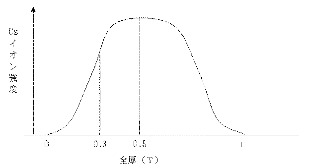
1;電池隔壁
2;燃料流通孔
3;酸化剤ガス流通孔
4;燃料室側拡散電極
5;酸化剤室側ガス拡散電極
6;固体高分子電解質(改質陽イオン交換膜)
7;燃料室
8;酸化剤室
1;
7;
Claims (6)
Priority Applications (1)
| Application Number | Priority Date | Filing Date | Title |
|---|---|---|---|
| JP2008316788A JP5111349B2 (en) | 2008-12-12 | 2008-12-12 | Modified hydrocarbon cation exchange membrane and method for producing the same |
Applications Claiming Priority (1)
| Application Number | Priority Date | Filing Date | Title |
|---|---|---|---|
| JP2008316788A JP5111349B2 (en) | 2008-12-12 | 2008-12-12 | Modified hydrocarbon cation exchange membrane and method for producing the same |
Publications (2)
| Publication Number | Publication Date |
|---|---|
| JP2010138308A JP2010138308A (en) | 2010-06-24 |
| JP5111349B2 true JP5111349B2 (en) | 2013-01-09 |
Family
ID=42348708
Family Applications (1)
| Application Number | Title | Priority Date | Filing Date |
|---|---|---|---|
| JP2008316788A Expired - Fee Related JP5111349B2 (en) | 2008-12-12 | 2008-12-12 | Modified hydrocarbon cation exchange membrane and method for producing the same |
Country Status (1)
| Country | Link |
|---|---|
| JP (1) | JP5111349B2 (en) |
Family Cites Families (3)
| Publication number | Priority date | Publication date | Assignee | Title |
|---|---|---|---|---|
| JPH05293345A (en) * | 1992-04-16 | 1993-11-09 | Tokuyama Soda Co Ltd | Semipermeable composite membrane |
| DE19919708A1 (en) * | 1999-04-30 | 2001-03-01 | Univ Stuttgart | Gradual alkylation of polymeric amines |
| EP1901379A4 (en) * | 2005-07-01 | 2012-06-06 | Tokuyama Corp | SEPARATION MEMBRANE FOR A FUEL CELL |
-
2008
- 2008-12-12 JP JP2008316788A patent/JP5111349B2/en not_active Expired - Fee Related
Also Published As
| Publication number | Publication date |
|---|---|
| JP2010138308A (en) | 2010-06-24 |
Similar Documents
| Publication | Publication Date | Title |
|---|---|---|
| KR101440672B1 (en) | Separation membrane for fuel cell, and method for production thereof | |
| US7923166B2 (en) | Separating membrane for fuel cell | |
| JP5133896B2 (en) | Membrane for polymer electrolyte fuel cell and membrane-electrode assembly | |
| KR101590651B1 (en) | Separation membrane for solid polymer fuel cell and separation membrane-catalyst electrode assembly | |
| KR101217947B1 (en) | Separation Membrane for Fuel Battery and Process for Producing the Same | |
| EP1965456B1 (en) | Electrolyte membrane-electrode membrane assembly for solid polymer fuel cell, process for producing the same, and fuel cell comprising said assembly | |
| JP5770163B2 (en) | Method for producing a membrane for a polymer electrolyte fuel cell | |
| US8148030B2 (en) | Separation membrane for fuel cell and production method thereof | |
| JP5551877B2 (en) | Membrane for fuel cell and manufacturing method thereof | |
| JP5004525B2 (en) | Fuel cell membrane | |
| JP5164149B2 (en) | Cation exchange membrane and method for producing the same | |
| JP2005032535A (en) | Junction element | |
| JP4883880B2 (en) | Method for producing diaphragm for direct methanol fuel cell | |
| JP5132115B2 (en) | Fuel cell membrane | |
| JP5111349B2 (en) | Modified hydrocarbon cation exchange membrane and method for producing the same | |
| JP5283826B2 (en) | Membrane electrode assembly and polymer electrolyte fuel cell | |
| JP2009093998A (en) | Membrane for direct liquid fuel type fuel cell and method for producing the same | |
| JP2010129415A (en) | Operation method of direct alcohol type fuel cell | |
| JP2009259808A (en) | Solid polymer electrolyte membrane, manufacturing method of solid polymer electrolyte membrane, and polymer electrolyte fuel cell |
Legal Events
| Date | Code | Title | Description |
|---|---|---|---|
| A621 | Written request for application examination |
Free format text: JAPANESE INTERMEDIATE CODE: A621 Effective date: 20110914 |
|
| A977 | Report on retrieval |
Free format text: JAPANESE INTERMEDIATE CODE: A971007 Effective date: 20120905 |
|
| TRDD | Decision of grant or rejection written | ||
| A01 | Written decision to grant a patent or to grant a registration (utility model) |
Free format text: JAPANESE INTERMEDIATE CODE: A01 Effective date: 20120911 |
|
| A01 | Written decision to grant a patent or to grant a registration (utility model) |
Free format text: JAPANESE INTERMEDIATE CODE: A01 |
|
| A61 | First payment of annual fees (during grant procedure) |
Free format text: JAPANESE INTERMEDIATE CODE: A61 Effective date: 20121009 |
|
| FPAY | Renewal fee payment (event date is renewal date of database) |
Free format text: PAYMENT UNTIL: 20151019 Year of fee payment: 3 |
|
| R150 | Certificate of patent or registration of utility model |
Free format text: JAPANESE INTERMEDIATE CODE: R150 |
|
| LAPS | Cancellation because of no payment of annual fees |