JP5111823B2 - Gas turbine engine assembly and method of assembling the same - Google Patents
Gas turbine engine assembly and method of assembling the same Download PDFInfo
- Publication number
- JP5111823B2 JP5111823B2 JP2006279803A JP2006279803A JP5111823B2 JP 5111823 B2 JP5111823 B2 JP 5111823B2 JP 2006279803 A JP2006279803 A JP 2006279803A JP 2006279803 A JP2006279803 A JP 2006279803A JP 5111823 B2 JP5111823 B2 JP 5111823B2
- Authority
- JP
- Japan
- Prior art keywords
- assembly
- fan assembly
- gas turbine
- coupled
- gearbox
- Prior art date
- Legal status (The legal status is an assumption and is not a legal conclusion. Google has not performed a legal analysis and makes no representation as to the accuracy of the status listed.)
- Expired - Fee Related
Links
Images


Classifications
-
- F—MECHANICAL ENGINEERING; LIGHTING; HEATING; WEAPONS; BLASTING
- F01—MACHINES OR ENGINES IN GENERAL; ENGINE PLANTS IN GENERAL; STEAM ENGINES
- F01D—NON-POSITIVE DISPLACEMENT MACHINES OR ENGINES, e.g. STEAM TURBINES
- F01D25/00—Component parts, details, or accessories, not provided for in, or of interest apart from, other groups
- F01D25/18—Lubricating arrangements
-
- F—MECHANICAL ENGINEERING; LIGHTING; HEATING; WEAPONS; BLASTING
- F02—COMBUSTION ENGINES; HOT-GAS OR COMBUSTION-PRODUCT ENGINE PLANTS
- F02C—GAS-TURBINE PLANTS; AIR INTAKES FOR JET-PROPULSION PLANTS; CONTROLLING FUEL SUPPLY IN AIR-BREATHING JET-PROPULSION PLANTS
- F02C7/00—Features, components parts, details or accessories, not provided for in, or of interest apart form groups F02C1/00 - F02C6/00; Air intakes for jet-propulsion plants
- F02C7/06—Arrangements of bearings; Lubricating
-
- F—MECHANICAL ENGINEERING; LIGHTING; HEATING; WEAPONS; BLASTING
- F01—MACHINES OR ENGINES IN GENERAL; ENGINE PLANTS IN GENERAL; STEAM ENGINES
- F01D—NON-POSITIVE DISPLACEMENT MACHINES OR ENGINES, e.g. STEAM TURBINES
- F01D25/00—Component parts, details, or accessories, not provided for in, or of interest apart from, other groups
- F01D25/16—Arrangement of bearings; Supporting or mounting bearings in casings
-
- F—MECHANICAL ENGINEERING; LIGHTING; HEATING; WEAPONS; BLASTING
- F02—COMBUSTION ENGINES; HOT-GAS OR COMBUSTION-PRODUCT ENGINE PLANTS
- F02K—JET-PROPULSION PLANTS
- F02K3/00—Plants including a gas turbine driving a compressor or a ducted fan
- F02K3/02—Plants including a gas turbine driving a compressor or a ducted fan in which part of the working fluid by-passes the turbine and combustion chamber
- F02K3/04—Plants including a gas turbine driving a compressor or a ducted fan in which part of the working fluid by-passes the turbine and combustion chamber the plant including ducted fans, i.e. fans with high volume, low pressure outputs, for augmenting the jet thrust, e.g. of double-flow type
- F02K3/072—Plants including a gas turbine driving a compressor or a ducted fan in which part of the working fluid by-passes the turbine and combustion chamber the plant including ducted fans, i.e. fans with high volume, low pressure outputs, for augmenting the jet thrust, e.g. of double-flow type with counter-rotating, e.g. fan rotors
-
- Y—GENERAL TAGGING OF NEW TECHNOLOGICAL DEVELOPMENTS; GENERAL TAGGING OF CROSS-SECTIONAL TECHNOLOGIES SPANNING OVER SEVERAL SECTIONS OF THE IPC; TECHNICAL SUBJECTS COVERED BY FORMER USPC CROSS-REFERENCE ART COLLECTIONS [XRACs] AND DIGESTS
- Y02—TECHNOLOGIES OR APPLICATIONS FOR MITIGATION OR ADAPTATION AGAINST CLIMATE CHANGE
- Y02T—CLIMATE CHANGE MITIGATION TECHNOLOGIES RELATED TO TRANSPORTATION
- Y02T50/00—Aeronautics or air transport
- Y02T50/60—Efficient propulsion technologies, e.g. for aircraft
Landscapes
- Engineering & Computer Science (AREA)
- Chemical & Material Sciences (AREA)
- Combustion & Propulsion (AREA)
- Mechanical Engineering (AREA)
- General Engineering & Computer Science (AREA)
- Structures Of Non-Positive Displacement Pumps (AREA)
- Support Of The Bearing (AREA)
- Turbine Rotor Nozzle Sealing (AREA)
Description
本発明は、総括的にはガスタービンエンジンに関し、より具体的には、ガスタービンエンジン組立体及びそれを組み立てる方法に関する。 The present invention relates generally to gas turbine engines, and more specifically to a gas turbine engine assembly and method of assembling the same.
少なくとも幾つかの公知のガスタービンエンジンは、前方ファン、コアエンジン及び出力タービンを含む。コアエンジンは、直列流れ関係の状態で互いに結合された少なくとも1つの圧縮機、燃焼器、高圧タービン及び低圧タービンを含む。より具体的には、圧縮機と高圧タービンとは、シャフトを介して結合されて高圧ロータ組立体を形成する。コアエンジンに流入した空気は、燃料と混合されかつ点火されて高エネルギーガス流を形成する。高エネルギーガス流は、高圧タービンを通って流れて高圧タービンを回転駆動し、次にシャフトが圧縮機を回転駆動するようになる。 At least some known gas turbine engines include a forward fan, a core engine, and a power turbine. The core engine includes at least one compressor, combustor, high pressure turbine, and low pressure turbine coupled together in a serial flow relationship. More specifically, the compressor and high pressure turbine are coupled via a shaft to form a high pressure rotor assembly. Air entering the core engine is mixed with fuel and ignited to form a high energy gas stream. The high energy gas stream flows through the high pressure turbine to rotationally drive the high pressure turbine, which in turn causes the shaft to rotationally drive the compressor.
ガス流は、該ガス流が高圧タービンの後方に配置された低圧タービンを通って流れるにつれて膨張する。低圧タービンは、駆動シャフトに結合されたファンを有するロータ組立体を含む。低圧タービンは、駆動シャフトを介してファンを回転駆動する。エンジン効率を増大させるのを可能にするために、少なくとも1つの公知のガスタービンエンジンは、二重反転ファン及び/又は二重反転ブースタ圧縮機に結合された二重反転低圧タービンを含む。 The gas stream expands as it flows through a low pressure turbine located behind the high pressure turbine. The low pressure turbine includes a rotor assembly having a fan coupled to a drive shaft. The low pressure turbine rotationally drives the fan via a drive shaft. In order to be able to increase engine efficiency, at least one known gas turbine engine includes a counter rotating low pressure turbine coupled to a counter rotating fan and / or a counter rotating booster compressor.
二重反転低圧タービンを支持するのを可能にするために、ガスタービンエンジン内に外側回転スプール、回転フレーム、中間タービンフレーム及び2つの同軸シャフトが設置される。上記の構成部品の設置はまた、第1のファン組立体及び第2のファン組立体が各々、それぞれ第1のタービン及び第2のタービンと同一の回転方向に回転するように、第1のファン組立体を第1のタービンに結合しまた第2のファン組立体を第2のタービンに結合することを可能にする。従って、そのようなエンジンの全重量、設計の複雑さ及び/又は製造コストが、増大する。
1つの態様では、ガスタービンエンジン組立体を提供する。本ガスタービンエンジンは、低圧タービンと、二重反転ファン組立体と、遊星ギヤボックスと、潤滑流体サンプとを含む。二重反転ファン組立体は、第1の方向に回転可能である第1のファン組立体と逆の第2の方向に回転可能である第2のファン組立体とを含む。低圧タービンは、駆動シャフトを介してファン組立体に結合される。遊星ギヤボックスは、入力部と出力部とを含む。ギヤボックス入力部は、低圧タービンに結合され、またギヤボックス出力部は、二重反転ファン組立体に結合される。潤滑流体サンプは、駆動シャフトによって少なくとも部分的に境界付けられる。遊星ギヤボックスは、潤滑流体サンプが実質的に該遊星ギヤボックスを囲むように潤滑流体サンプ内に収容される。 In one aspect, a gas turbine engine assembly is provided. The gas turbine engine includes a low pressure turbine, a counter-rotating fan assembly, a planetary gearbox, and a lubricating fluid sump. The counter rotating fan assembly includes a first fan assembly that is rotatable in a first direction and a second fan assembly that is rotatable in a second direction opposite to the first fan assembly. The low pressure turbine is coupled to the fan assembly via a drive shaft. The planetary gear box includes an input unit and an output unit. The gearbox input is coupled to the low pressure turbine, and the gearbox output is coupled to the counter rotating fan assembly. The lubricating fluid sump is at least partially bounded by the drive shaft. The planetary gear box is housed within the lubricating fluid sump such that the lubricating fluid sump substantially surrounds the planetary gear box.
別の態様では、ガスタービンエンジン組立体を提供する。本エンジン組立体は、二重反転ファン組立体と、コアエンジンと、遊星ギヤボックスと、潤滑流体サンプとを含む。二重反転ファン組立体は、第1の方向に回転可能である第1のファン組立体と逆の第2の方向に回転可能である第2のファン組立体とを含む。コアエンジンは、二重反転ファン組立体の下流に配置され、駆動シャフトを介して該二重反転ファン組立体に結合される。遊星ギヤボックスは、二重反転ファン組立体に結合される。潤滑流体サンプは、コアエンジンと二重反転ファン組立体との間に結合される。潤滑流体サンプは、駆動シャフトによって少なくとも部分的に境界付けられる。ギヤボックスは、該ギヤボックスが二重反転ファン組立体によって発生した軸方向加重から実質的に分離されるように潤滑流体サンプ内に収容される。 In another aspect, a gas turbine engine assembly is provided. The engine assembly includes a counter-rotating fan assembly, a core engine, a planetary gearbox, and a lubricating fluid sump. The counter-rotating fan assembly includes a first fan assembly that is rotatable in a first direction and a second fan assembly that is rotatable in a second direction opposite to the first fan assembly. The core engine is disposed downstream of the counter rotating fan assembly and is coupled to the counter rotating fan assembly via a drive shaft. The planetary gearbox is coupled to the counter rotating fan assembly. A lubricating fluid sump is coupled between the core engine and the counter-rotating fan assembly. The lubricating fluid sump is at least partially bounded by the drive shaft. The gearbox is housed in the lubricating fluid sump so that the gearbox is substantially separated from the axial load generated by the counter-rotating fan assembly.
さらに別の態様では、ガスタービンエンジンを組み立てる方法を提供する。本方法は、第1のファン組立体と第2のファン組立体とを含む二重反転ファン組立体に対して駆動シャフトの周りで回転可能な低圧タービンを結合して、第1のファン組立体が第1の方向に回転しかつ第2のファン組立体が逆の第2の方向に回転するようにする段階を含む。本方法はまた、駆動シャフトの周りで実質的に円周方向に遊星ギヤボックスを結合して、ギヤボックスの入力部が低圧タービンに結合されかつギヤボックスの出力部が二重反転ファン組立体に結合され、またギヤボックスが、該ギヤボックスを実質的に囲む潤滑流体サンプ内に配置されるようにする段階を含む。 In yet another aspect, a method for assembling a gas turbine engine is provided. The method combines a low pressure turbine rotatable about a drive shaft to a counter rotating fan assembly including a first fan assembly and a second fan assembly to provide a first fan assembly. Rotating in a first direction and causing the second fan assembly to rotate in the opposite second direction. The method also couples the planetary gearbox substantially circumferentially around the drive shaft so that the gearbox input is coupled to the low pressure turbine and the gearbox output is the counter-rotating fan assembly. Coupled, and including allowing the gear box to be disposed within a lubricating fluid sump substantially surrounding the gear box.
図1は、長手方向軸線11を有する例示的なタービンエンジン組立体10の一部分の断面図である。この例示的な実施形態では、タービンエンジン組立体10は、その全体をフレーム13によって定められたコアガスタービンエンジン12を含む。低圧タービン14が、コアガスタービンエンジン12の軸方向後方に結合され、二重反転ファン組立体16が、コアガスタービンエンジン12の軸方向前方に結合される。
FIG. 1 is a cross-sectional view of a portion of an exemplary
コアガスタービンエンジン12は、環状のコアエンジン入口22を形成した外側ケーシング20を含む。ケーシング20は、低圧ブースタ圧縮機24を囲んで流入空気の圧力を第1の圧力レベルまで増大させるのを可能にする。1つの実施形態では、コアガスタービンエンジン12は、オハイオ州シンシナティ所在のGeneral Electric Aircraft Enginesから入手可能なコアCFM56型ガスタービンエンジンである。
The core
高圧多段軸流圧縮機26は、ブースタ圧縮機24から加圧空気を受け、この空気の圧力を第2のより高い圧力レベルにさらに増大させる。高圧空気は、燃焼器28に送られ、燃料と混合される。燃料−空気混合気は点火されて、加圧空気の温度及びエネルギーレベルを上昇させる。高エネルギー燃焼生成物は、第1の又は高圧タービン30に流れて第1の回転駆動シャフト32を介して圧縮機26を駆動するようにし、次に第2の又は低圧タービン14に流れて第1の駆動シャフト32と同軸に結合された第2の回転駆動シャフト34を介して二重反転ファン組立体16及びブースタ圧縮機24を駆動するのを可能にする。低圧タービン14を駆動した後に、燃焼生成物は、排出ノズル36を介してタービンエンジン組立体10から流出して推進ジェット推力を提供する。
The high pressure multistage
二重反転ファン組立体16は、長手方向軸線11の周りで回転するように構成された第1の又は前方ファン組立体50と第2の又は後方ファン組立体52とを含む。本明細書では「前方ファン」及び「後方ファン」という用語を使用して、ファン組立体50がファン組立体52の軸方向上流に結合されることを表している。1つの実施形態では、ファン組立体50及び52は、図1〜図3に示すように、コアガスタービンエンジン12の前方端部に配置される。別の実施形態では、ファン組立体50及び52は、コアガスタービンエンジン12の後方端部に配置される。ファン組立体50及び52は各々、それぞれ少なくとも1列のロータブレード60及び62を含み、ナセル64内に配置される。ロータブレード60は、ロータディスク66に結合され、またロータブレード62は、ロータディスク68に結合される。
The
1つの実施形態では、ブースタ圧縮機24は、それぞれのロータディスク72に結合された複数列のロータブレード70を含む。ブースタ圧縮機24は、入口ガイドベーン組立体74の後方に配置され、該ブースタ圧縮機24が後方ファン組立体52の回転速度と実質的に等しい回転速度で回転するように後方ファン組立体52に結合される。ブースタ圧縮機24は、3列のみのロータブレード70を有するものとして図示しているが、ブースタ圧縮機24は、1列のみのロータブレード70又は複数列のガイドベーン76と交差指状に配置された複数列のロータブレード70のようなあらゆる適当な数及び/又は列のロータブレード70を有することができる。1つの実施形態では、入口ガイドベーン76は、ブースタケース78に対して固定又は堅固に結合される。別の実施形態では、ロータブレード70をロータディスク72に対して回転可能に結合して、入口ガイドベーン76が、エンジン作動中にブースタ圧縮機24を通って流れる空気の量を変えるのを可能にするように可動になるようにする。さらに別の実施形態では、タービンエンジン組立体10は、ブースタ圧縮機24を含まない。
In one embodiment,
図1に示すように、低圧タービン14は、前方ファン組立体50が第1の回転方向80に回転するようにシャフト34を介して前方ファン組立体50に対して結合される。後方ファン組立体52は、該後方ファン組立体52が逆の第2の回転方向82に回転するように駆動シャフト34及び/又は低圧タービン14に対して結合される。
As shown in FIG. 1, the
図2は、図1に示す二重反転ファン組立体16の一部分の概略図である。1つの実施形態では、第1のファン組立体50は、長手方向軸線11の周りに配置されたコーン84を含む。コーン84は、図2に示すように、第1の又は前方端部86においてロータディスク66に連結され、また第2の又は後方端部88において駆動シャフト34に連結される。第2のファン組立体52は、長手方向軸線11に沿ってコーン84の少なくとも一部分の周りに同軸に配置されたコーン90を含む。コーン90は、以下に一層詳しく説明するように、第1の又は前方端部92においてロータディスク68に結合され、また第2の又は後方端部94においてギヤボックス100の出力部に及び/又は転がり軸受組立体を介してコーン84の後方端部88に結合される。
FIG. 2 is a schematic view of a portion of the
図3は、図2に示す二重反転ファン組立体16の一部分の概略図である。1つの実施形態では、二重反転ファン組立体16はまた、後方ファン組立体52と駆動シャフト34との間に結合されて、前方ファン組立体50が回転する回転方向80に対して逆の回転方向82に後方ファン組立体52を回転させるのを可能にするギヤボックス100を含む。ギヤボックス100は、ほぼトロイダル形状を有し、駆動シャフト34の周りで円周方向に配置されて実質的に駆動シャフト34の周りに延びるように構成される。図3に示すように、ギヤボックス100は、支持構造体102と、支持構造体102内に結合された少なくとも1つの歯車103と、入力部104と、出力部106とを含む。
FIG. 3 is a schematic view of a portion of the
1つの実施形態では、ギヤボックス100は、約2.0対1の歯車比を有し、前方ファン組立体50が後方ファン組立体52の回転速度の約2倍の回転速度で回転するようになる。別の実施形態では、前方ファン組立体50は、後方ファン組立体52の回転速度の約0.67倍から後方ファン組立体52の回転速度よりも速い約2.1倍までの間である回転速度で回転する。この実施形態では、前方ファン組立体50は、後方ファン組立体52の回転速度よりも大きいか、後方ファン組立体52の回転速度と等しいか、又は後方ファン組立体52の回転速度よりも小さい回転速度で回転することができる。
In one embodiment, the
1つの実施形態では、図1〜図3に示すスラスト軸受組立体110のような第1の軸受組立体が、駆動シャフト34及び/又は長手方向軸線11の周りに配置される。スラスト軸受組立体110は、駆動シャフト34とコアガスタービンエンジン12のフレーム13との間を作動的に結合しかつ/又はそれらの間に取付けられる。さらに図3を参照すると、1つの実施形態では、スラスト軸受組立体110は、駆動シャフト34に対して取付けられた半径方向配置のインナレース111を含む。図3に示すように、インナレース111は、駆動シャフト34に作動的に結合された駆動シャフト延長部112に取付けられて、インナレース111は、長手方向軸線11の周りで駆動シャフト34と共に回転可能になる。1つの特定の実施形態では、駆動シャフト延長部112は、駆動シャフト34にスプライン嵌合される。インナレース111は、スラスト軸受組立体110の内側溝114を形成した表面113を有する。内側溝114を形成した表面113は、ほぼ円弧状輪郭を有する。
In one embodiment, a first bearing assembly, such as the
スラスト軸受組立体110は、フレーム13に固定結合された半径方向配置のアウタレース116を含む。1つの実施形態では、アウタレース116及び/又はフレーム13は、以下に一層詳しく説明するように、二重反転ファン組立体16及び/又はブースタ圧縮機24によって出現又は発生したスラスト荷重及び/又は力の伝達のための基盤領域として作用する。アウタレース116は、表面113と全体的に対向した表面117を有し、この表面117は、スラスト軸受組立体110の外側溝118を形成する。外側溝118を形成した表面117は、ほぼ円弧状輪郭を有する。複数のベアリング119のような少なくとも1つのローラ要素が、インナレース111とアウタレース116との間に運動可能に配置される。各ベアリング119は、内側溝114及び外側溝118と転がり接触して、駆動シャフト34がギヤボックス100に対して自由に回転するのを可能にする。
The
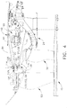
図4を参照すると、スラスト軸受組立体120のような第2の軸受組立体が、長手方向軸線11の周りで半径方向に配置される。1つの実施形態では、スラスト軸受組立体120は、コーン84の前方端部86又はその近傍などの第1のファン組立体50の前方端部部分とコーン90の前方端部92又はその近傍などの第2のファン組立体52の前方端部部分との間を作動的に結合しかつ/又はそれらの間に取付けられる。1つの実施形態では、スラスト軸受組立体120は、コーン84の外表面に対して取付けられた半径方向配置のインナレース122を含む。図4に示すように、インナレース122はコーン84に取付けられて、インナレース122は、長手方向軸線11の周りで第1のファン組立体50と共に回転可能になる。インナレース122は、スラスト軸受組立体120の内側溝124を形成した表面123を有する。内側溝124を形成した表面123は、ほぼ円弧状輪郭を有する。
With reference to FIG. 4, a second bearing assembly, such as a
スラスト軸受組立体120は、コーン90の内表面に対して取付けられた半径方向配置のアウタレース126を含む。図4に示すように、アウタレース126はコーン90に取付けられて、アウタレース126は、長手方向軸線11の周りで第2のファン組立体52と共に回転可能になる。アウタレース126は、表面123と全体的に対向した表面127を有し、この表面127は、スラスト軸受組立体120の外側溝128を形成する。外側溝128を形成した表面127は、ほぼ円弧状輪郭を有する。複数のベアリング129のような少なくとも1つのローラ要素が、インナレース122とアウタレース126との間に運動可能に配置される。各ベアリング129は、内側溝124及び外側溝128と転がり接触して、第1のファン組立体50及び/又は第2のファン組立体52の相対回転運動を可能にする。
1つの実施形態では、スラスト軸受組立体110及び/又は120は、前方ファン組立体50及び/又は後方ファン組立体52を相対的に一定の軸方向位置に維持するのを可能にする。二重反転ファン組立体16の作動中に、第1のファン組立体50によって発生したスラスト荷重及び/又は力は、第1のファン組立体50から直接第1のスラスト軸受組立体110に伝達される。さらに、作動中に第2のファン組立体52及び/又はブースタ圧縮機24によって発生したスラスト荷重及び/又は力は、第2のファン組立体52及び/又はブースタ圧縮機24から第2のスラスト軸受組立体120に、また第2のスラスト軸受組立体120から駆動シャフト34を介して第1のスラスト軸受組立体110に伝達される。スラスト荷重及び/又は力をスラスト軸受組立体110及び/又はスラスト軸受組立体120に伝達する結果として、第2のファン組立体52に対して作動的に結合されたギヤボックス100を介してのスラスト荷重及び/又は力の伝達が、防止又は制限される。別の実施形態では、当業者に公知でありまた本明細書に示した教示によって手引きされるあらゆる適当な軸受組立体を、軸受組立体110及び/又は軸受組立体120として或いはこれらの軸受組立体に加えて使用することができる。
In one embodiment, the
1つの実施形態では、図4に示すように、ローラ軸受組立体130のような軸受組立体が、前方端部92又はその近傍においてコーン90の外表面の周りに配置される。ローラ軸受組立体130は、フレーム13と前方端部92との間に連結される。1つの実施形態では、ローラ軸受組立体130は、スラスト軸受組立体120と組み合わさって差動軸受組立体として作用して、第2のファン組立体52を支持しかつ/又は第2のファン組立体52からのスラスト荷重及び/又は力をフレーム13に伝達する。1つの実施形態では、ローラ軸受組立体130は、図4に示すように、コーン90に対して取付けられたインナレース132を含む。インナレース132はコーン90の前方端部92に取付けられて、インナレース132は、長手方向軸線11の周りで第2のファン組立体52と共に回転可能になる。インナレース132は、ローラ軸受組立体130の内側溝134を形成した表面133を有する。
In one embodiment, as shown in FIG. 4, a bearing assembly, such as a
ローラ軸受組立体130は、フレーム13に固定結合されたアウタレース136を含む。1つの実施形態では、アウタレース136は、構造支持部材15及び/又はフレーム13に対して固定結合される。構造支持部材15及び/又はフレーム13は、二重反転ファン組立体16及び/又はブースタ圧縮機24によって出現又は発生したスラスト荷重及び/又は力の伝達のための基盤領域として作用する。アウタレース136は、表面133と全体的に対向した表面137を有し、この表面137は、ローラ軸受組立体130の外側溝138を形成する。複数のローラ139のような少なくとも1つのローラ要素が、インナレース132とアウタレース136との間に運動可能に配置される。各ローラ139は、内側溝134及び外側溝138と転がり接触する。
The
1つの実施形態では、図3に示すように、ローラ軸受組立体140のような軸受組立体が、後方端部88又はその近傍においてコーン84の外表面の周りに配置される。ローラ軸受組立体140は、コーン84とコーン90との間に連結される。ローラ軸受組立体140は、図2に示すように、後方端部88に対して取付けられたインナレース142を含む。インナレース142はコーン84に取付けられて、インナレース142は、長手方向軸線11の周りで第1のファン組立体50と共に回転可能になる。インナレース142は、ローラ軸受組立体140の内側溝144を形成した表面143を有する。
In one embodiment, as shown in FIG. 3, a bearing assembly, such as a
ローラ軸受組立体140は、図3に示すように、コーン90の後方端部94に対して取付けられたアウタレース146を含む。アウタレース146はコーン90に取付けられて、アウタレース146は、長手方向軸線11の周りで第2のファン組立体52と共に回転可能になる。アウタレース146は、表面143と全体的に対向した表面147を有し、この表面147は、ローラ軸受組立体140の外側溝148を形成する。複数のローラ149のような少なくとも1つのローラ要素が、インナレース142とアウタレース146との間に運動可能に配置される。各ローラ149は、内側溝144及び外側溝148と転がり接触して、コーン84及び/又はコーン90の相対回転運動を可能にする。
The
この実施形態では、ローラ軸受組立体130及び140は、後方ファン組立体52が前方ファン組立体50に対して自由に回転することができるように、後方ファン組立体52に回転支持を与えることを可能にする。従って、ローラ軸受組立体130及び140は、二重反転ファン組立体16内で後方ファン組立体52を相対的に一定の半径方向位置に維持することを可能にする。別の実施形態では、当業者に公知でありまた本明細書に示した教示によって手引きされるあらゆる適当な軸受組立体を、軸受組立体130及び/又は軸受組立体140として或いはこれらの軸受組立体に加えて使用することができる。
In this embodiment, the
1つの実施形態では、図3に示すように、ギヤボックス100が、コアタービンエンジン12のフレーム13のようなガスタービンエンジン10の固定又は静止構成部品に連結される。ギヤボックス入力部104は、駆動シャフト34にスプライン嵌合された駆動シャフト延長部112を介して第2の駆動シャフト34に回転可能に結合される。ギヤボックス出力部106は、出力部構造体160を介して後方ファン組立体52に回転可能に結合される。出力部構造体160の第1の端部は、ギヤボックス出力部106にスプライン嵌合され、出力部構造体160の第2の端部は、後方ファン前方シャフト168に結合されて後方ファン組立体52を駆動するのを可能にする。
In one embodiment, as shown in FIG. 3, the
図3を参照すると、1つの実施形態では、ガスタービンエンジン組立体10は、ギヤボックス100を二重反転ファン組立体16に取付けるためのスプラインシステム200を含む。ギヤボックス100は、例えばギヤボックス支持構造体102においてコアガスタービンエンジン12のフレーム13に対して固定又は堅固に結合される。スプラインシステム200は、ギヤボックス100を第1のファン組立体50及び/又は第2のファン組立体52から分離して、二重反転ファン組立体16の作動の結果としてギヤボックス100上にスラスト荷重及び/又は力が作用するのを防止又は制限する。第1のファン組立体50は、該第1のファン組立体50が図1の回転矢印80によって示した第1の方向に回転するように、入力部104に対して回転可能に結合される。第2のファン組立体52は、該第2のファン組立体52が第1の方向とは逆の図1の回転矢印82によって示した第2の方向に回転するように、出力部106に対して回転可能に結合される。
With reference to FIG. 3, in one embodiment, gas
図3に示すように、スプラインシステム200は、スプライン組立体202、204、206及び/又は208のような複数のスプライン組立体を含む。1つの実施形態では、第1のスプライン組立体202は、駆動シャフト延長部112に対して入力部104を結合する。駆動シャフト延長部112は、図3に示すように、第1の部分210と第2の部分212とを含む。第1のスプライン組立体202は、第2の部分212に対して入力部104を結合し、また第1のスプライン組立体202と同一又は同様である第2のスプライン組立体204は、駆動シャフト34に対して入力部104を回転可能に結合するために第2の部分212に対して第1の部分210を結合する。さらに、第2のスプライン組立体204は、ギヤボックス100に対して軸方向に、つまりタービンエンジン組立体10の長手方向軸線11に沿って又は長手方向軸線11に平行にスラスト軸受組立体110が運動するのを可能にする。
ラジアル・ギヤボックス100は、第1の部分210と第2の部分212の間に結合されたスラストばねを含むことができ、このスラストばねが、二重反転ファン組立体16によって発生したスラストを吸収するように構成されている。これら第1の部分210、第2の部分212及びスラストばねは、互いに一体形に形成するでき、このスラストばねには、該スラストばねを貫通する複数の開口が形成され、この開口により、二重反転ファン組立体16によって発生したスラストを吸収するのを可能にする。
As shown in FIG. 3, the
The
1つの実施形態では、スプライン組立体204は、その外周部の周りに位置した複数のスプラインを形成した部材を含む。駆動シャフト延長部112の第2の部分212に連結されたこの部材は、第1の部分210に連結された協働するハウジング内に形成された空洞内に配置可能であって、複数のスプラインがハウジングの内周部上に形成されたスロットと噛合又は嵌合して、ねじり荷重及び/又は力を駆動シャフト延長部112の第2の部分212から第1の部分210に伝達するようにする。さらに、この部材は、協働するハウジング内に配置されて、ハウジング内での部材の軸方向の、例えば長手方向軸線11に沿った又は長手方向軸線11に平行な運動を可能にし、これにより、第1の部分210に対する第2の部分212の軸方向運動を可能にする。
In one embodiment, the spline assembly 204 includes a plurality of splined members positioned about its outer periphery. The member coupled to the
1つの特定の実施形態では、各スプライン組立体204、206及び208は、スプライン組立体204に関して上述したように、同一又は同様である。第3のスプライン組立体206は、出力部構造体160に対して出力部106を摺動可能に結合する。第3のスプライン組立体206は、ギヤボックス100に対する後方ファン前方シャフト168の軸方向運動を可能にする。1つの実施形態では、第4のスプライン組立体208は、駆動シャフト34に対して駆動シャフト延長部112の第1の部分210を摺動可能に結合する。作動中に、スプライン組立体202、204、206及び/又は208は、ねじり又はトルク荷重及び/又は力のみをギヤボックス100に通過させて、ギヤボックス100が低圧タービン14のフレームに対して実質的に一定の位置に保たれるようにする。
In one particular embodiment, each
1つの実施形態では、駆動シャフト延長部112及び/又は出力部構造体160は、ギヤボックス100の半径方向偏位を吸収する少なくとも1つの可撓性アームを含む。特定の実施形態では、第2の部分212は、スプライン組立体202を介して入力部104に結合された半径方向内側部分230と、スプライン組立体204を介して第1の部分210に結合された半径方向外側部分232とを含む。第2の部分212は、内側部分230又はその近傍において第1の厚さを有し、また外側部分232又はその近傍において、第1の厚さよりも小さい第2の厚さを有する。この特定の実施形態では、第2の部分212の厚さは、半径方向内側部分230から半径方向外側部分232まで徐々に減少する。第2の厚さは、第2の部分212が所定のねじり荷重及び/又は力を受けた時に、第2の部分212が第1の部分210から分離することになる、つまり第2の部分212が破断することになるように選択される。エンジン組立体10の作動中に、後方ファン組立体52には、比較的大きな半径方向荷重及び/又は力が加わる可能性がある。比較的大きな半径方向荷重及び/又は力を吸収するために、また連続的なエンジン作動を保証するために、1つの実施形態では、第2の部分212が破断して、後方ファン組立体52を自由転輪させながら前方ファン組立体50が作動し続けるようにする。
In one embodiment, drive
作動中に、第2の駆動シャフト34が回転すると、第2の駆動シャフト34は入力部104を第1の回転方向に回転させ、入力部104が次に、出力部106を逆の第2の回転方向に回転させる。出力部構造体160は後方ファン組立体52に結合されているので、駆動シャフト34は、ギヤボックス100を介して後方ファン組立体52を逆の第2の方向82に回転させる。1つの実施形態では、ギヤボックス100は、出力部構造体160と後方ファン組立体52を支持するように構成された構造支持部材15との間に少なくとも部分的に形成されたサンプ170内に配置される。エンジン作動中、ギヤボックス100は、エンジン作動の間にギヤボックス100を連続的に潤滑するために、サンプ170内に収容された潤滑流体内に少なくとも部分的に沈められる。
In operation, when the
より具体的には、サンプ170は、コーン84によって形成された半径方向内側境界と、軸受組立体130によって形成された軸方向前方境界と、支持構造体15によって形成された半径方向外側境界と、構造体13、高速圧縮機26及びシャフト34によって形成された軸方向後方境界とを有する。
More specifically, the
ガスタービンエンジン10が回転すると、潤滑オイルは、遠心力により半径方向外向きに強制的に押し流される。オイルは、軸受組立体110、120、130及び140に流れて、これら軸受を潤滑する。さらに、潤滑流体は、ギヤボックス100の周りにかつギヤボックス100を通って流れて、該ギヤボックス内に結合された様々な歯車及び塾受を潤滑するのを可能にする。より具体的には、ギヤボックス100は、外側ケーシングを含んでおらず、サンプ内に流れた潤滑流体は、ギヤボックス100内の露出した歯車及び軸受上を流れる。ギヤボックス100並びに軸受組立体110、120、130及び140を潤滑した後に、使用済みオイルは、構造部材13内に形成された開口115を通って流れ、ガスタービンエンジン組立体10から流出する。より具体的には、ガスタービンエンジン10は回転するので、遠心力により潤滑オイルが半径方向外向きに構造部材15の内面に向かって強制的に押し流され、そこで潤滑オイルは、部材15に沿って流れて該部材を貫通する開口115を通って流れる。
When the
本明細書に記載したガスタービンエンジン組立体は、減速型単回転低圧タービンを有する二重反転ファン組立体を含む。本組立体は、公知の二重反転低圧タービンに関連した複雑さの少なくとも幾つかを軽減するのを可能にする。より具体的には、本明細書に記載したガスタービンエンジン組立体は、駆動シャフトの周りで半径方向に延びかつほぼ半径方向形状の(ラジアル形状の)ギヤボックス内に結合されたトロイダル形状ギヤボックスを含む。ギヤボックスは外側ハウジングを含まないので、ギヤボックス内の歯車は、サンプ内に流れる潤滑流体に直接曝される。その結果、ガスタービンエンジン組立体の寸法及び重量は、公知のギヤボックス組立体を囲む外側ケーシングを排除することによって減少させることができる。 The gas turbine engine assembly described herein includes a counter-rotating fan assembly having a reduced speed single rotation low pressure turbine. The assembly makes it possible to reduce at least some of the complexity associated with known counter rotating low pressure turbines. More specifically, the gas turbine engine assembly described herein includes a toroidal gearbox that extends radially about a drive shaft and is coupled within a substantially radial (radial) gearbox. including. Since the gear box does not include an outer housing, the gears in the gear box are directly exposed to the lubricating fluid flowing in the sump. As a result, the size and weight of the gas turbine engine assembly can be reduced by eliminating the outer casing surrounding the known gearbox assembly.
上述したガスタービンエンジン組立体及びガスタービンエンジン組立体を組み立てる方法は、二重反転ファン組立体及び/又はブースタ圧縮機によって発生したロータスラスト荷重及び/又は力を低圧タービンによって発生したロータスラスト荷重及び/又は力と均衡させることを可能にする。より具体的には、本発明は、前方ファン組立体によって発生したロータスラスト荷重及び/又は力を後方スラスト軸受組立体に直接伝達することを可能にする。後方ファン組立体及び/又はブースタ圧縮機によって発生したロータスラスト荷重及び/又は力は、前方スラスト軸受組立体及び駆動シャフトを介して後方スラスト軸受に伝達される。その結果、後方ファン組立体及び/又はブースタ圧縮機によって発生したロータスラスト荷重及び/又は力、並びに前方ファン組立体によって発生したロータスラスト荷重及び/又は力は、後方スラスト軸受組立体によって支えられ、かつこれまた後方スラスト軸受組立体によって支えられる低圧タービンロータスラスト荷重及び/又は力によって相殺される。さらに、ギヤボックスへのロータスラスト荷重及び/又は力の伝達は防止又は制限されて、ギヤボックスは、ねじり荷重及び/又は力のみを支えるようになる。 The gas turbine engine assembly and method of assembling the gas turbine engine assembly described above includes a rotor thrust load generated by a counter rotating fan assembly and / or a booster compressor and / or a rotor thrust load generated by a low pressure turbine and / or a force. Allows balancing with force. More specifically, the present invention allows the rotor thrust load and / or force generated by the front fan assembly to be transmitted directly to the rear thrust bearing assembly. Rotor thrust loads and / or forces generated by the rear fan assembly and / or booster compressor are transmitted to the rear thrust bearing via the front thrust bearing assembly and drive shaft. As a result, the rotor thrust load and / or force generated by the rear fan assembly and / or booster compressor and the rotor thrust load and / or force generated by the front fan assembly are supported by the rear thrust bearing assembly, And also offset by the low pressure turbine rotor thrust load and / or force supported by the aft thrust bearing assembly. Further, the transmission of rotor thrust load and / or force to the gear box is prevented or limited so that the gear box only supports torsional loads and / or forces.
以上、ガスタービンエンジン組立体及びガスタービンエンジン組立体を組み立てる方法の例示的な実施形態を詳細に説明している。本組立体及び方法は、本明細書に記載した特定の実施形態に限定されるものではなく、むしろ本組立体の構成要素及び/又は本方法の段階は、本明細書に記載したその他の構成要素及び/又は段階とは独立してかつ別個に利用することができる。さらに、記載した組立体の構成要素及び/又は方法の段階はまた、その他の組立体及び/又は方法において特徴づけることができ或いはそれらと組み合わせて使用することができ、本明細書に記載した組立体及び/又は方法のみで実施することに限定されるものではない。 The exemplary embodiments of the gas turbine engine assembly and the method of assembling the gas turbine engine assembly are described in detail above. The assembly and method are not limited to the specific embodiments described herein, but rather the components of the assembly and / or the steps of the method may include other configurations described herein. It can be used independently and separately from the elements and / or steps. Further, the components and / or method steps of the described assembly can also be characterized in or used in combination with other assemblies and / or methods, and the set described herein. It is not limited to implementing only in three dimensions and / or methods.
様々な具体的な実施形態に関して本発明を説明してきたが、本発明が特許請求の範囲の技術思想及び技術的範囲内の変更で実施することができることは、当業者には明らかであろう。 While the invention has been described in terms of various specific embodiments, those skilled in the art will recognize that the invention can be practiced with modification within the spirit and scope of the claims.
10 タービンエンジン組立体
11 長手方向軸線
12 コアタービンエンジン
13 フレーム
14 低圧タービン
15 構造支持部材
16 回転ファン組立体
20 外側ケーシング
22 エンジン入口
24 ブースタ圧縮機
26 高速圧縮機
28 燃焼器
30 高圧タービン
32 第1の回転駆動シャフト
34 第2の回転駆動シャフト
36 排出ノズル
50 第1のファン組立体
52 第2のファン組立体
60 ロータブレード
62 ロータブレード
64 ナセル
66 ロータディスク
68 ロータディスク
70 ロータブレード
72 ロータディスク
74 入口ガイドベーン組立体
76 ガイドベーン
78 ブースタケース
80 第1の回転方向
82 第2の回転方向
84 コーン
86 第1の又は前方端部
88 第2の又は後方端部
90 コーン
92 第1の又は前方端部
94 第2の又は後方端部
100 ギヤボックス
102 ギヤボックスハウジング
103 歯車
104 入力部
106 出力部
110 第1のスラスト軸受組立体
111 インナレース
112 軸受支持構造体
113 表面
114 内側溝
115 開口
116 アウタレース
117 表面
118 外側溝
119 複数のベアリング
120 第2のスラスト軸受組立体
122 インナレース
123 表面
124 内側溝
126 アウタレース
127 表面
128 外側溝
129 複数のベアリング
130 ローラ軸受組立体
132 インナレース
133 表面
134 内側溝
136 アウタレース
137 表面
138 外側溝
139 複数のローラ
140 ローラ軸受組立体
142 インナレース
143 表面
144 内側溝
146 アウタレース
147 表面
148 外側溝
149 複数のローラ
159 開口
160 出力部構造体
168 後方ファン前方シャフト
170 サンプ
200 スプラインシステム
204 第2のスプライン組立体
206 第3のスプライン組立体
208 第4のスプライン組立体
210 第1の部分
212 第2の部分
230 内側部分
232 外側部分
DESCRIPTION OF SYMBOLS 10 Turbine engine assembly 11 Longitudinal axis 12 Core turbine engine 13 Frame 14 Low pressure turbine 15 Structural support member 16 Rotating fan assembly 20 Outer casing 22 Engine inlet 24 Booster compressor 26 High speed compressor 28 Combustor 30 High pressure turbine 32 1st Rotation drive shaft 34 Second rotation drive shaft 36 Discharge nozzle 50 First fan assembly 52 Second fan assembly 60 Rotor blade 62 Rotor blade 64 Nacelle 66 Rotor disk 68 Rotor disk 70 Rotor blade 72 Rotor disk 74 Inlet Guide vane assembly 76 Guide vane 78 Booster case 80 First rotational direction 82 Second rotational direction 84 Cone 86 First or front end 88 Second or rear end 90 Cone 92 First Is the front end 94 second or rear end 100 gear box 102 gear box housing 103 gear 104 input section 106 output section 110 first thrust bearing assembly 111 inner race 112 bearing support structure 113 surface 114 inner groove 115 opening 116 outer race 117 surface 118 outer groove 119 plural bearings 120 second thrust bearing assembly 122 inner race 123 surface 124 inner groove 126 outer race 127 surface 128 outer groove 129 plural bearings 130 roller bearing assembly 132 inner race 133 surface 134 inside Side groove 136 Outer race 137 Surface 138 Outer groove 139 Multiple rollers 140 Roller bearing assembly 142 Inner race 143 Surface 144 Inner groove 146 Outer race 147 Table 148 Outer groove 149 Multiple rollers 159 Opening 160 Output structure 168 Rear fan front shaft 170 Sump 200 Spline system 204 Second spline assembly 206 Third spline assembly 208 Fourth spline assembly 210 First part 212 Second part 230 Inner part 232 Outer part
Claims (9)
第1の方向(80)に回転可能な第1のファン組立体(50)と逆の第2の方向(82)に回転可能な第2のファン組立体(52)とを含み、駆動シャフト(34)を介してそれに対して前記低圧タービンが結合された二重反転ファン組立体(16)と、
前記低圧タービンに結合された入力部(104)と前記二重反転ファン組立体に結合された出力部(106)とを含むラジアル・ギヤボックス(100)と、
前記駆動シャフトによって少なくとも部分的に形成され、それが前記ギヤボックスを囲むように該ギヤボックスがその中に収容された潤滑流体サンプ(170)と、
を含み、
前記潤滑流体サンプ(170)が、前記二重反転ファン組立体(16)によって発生した軸方向荷重から前記ギヤボックス(100)を分離するのを可能にすることを特徴とする、ガスタービンエンジン組立体(10)。 A low pressure turbine (14);
A first fan assembly (50) rotatable in a first direction (80) and a second fan assembly (52) rotatable in a second opposite direction (82), the drive shaft ( 34 ) a counter-rotating fan assembly (16) to which the low-pressure turbine is coupled via
A radial gearbox (100) including an input (104) coupled to the low pressure turbine and an output (106) coupled to the counter-rotating fan assembly;
A lubricating fluid sump (170) formed at least in part by the drive shaft, the gearbox being housed therein such that it surrounds the gearbox;
Including
Gas turbine engine set, characterized in that the lubricating fluid sump (170) enables the gearbox (100) to be separated from the axial load generated by the counter rotating fan assembly (16). Solid (10).
第1の方向(80)に回転可能な第1のファン組立体(50)と逆の第2の方向(82)に回転可能な第2のファン組立体(52)とを含み、駆動シャフト(34)を介してそれに対して前記低圧タービンが結合された二重反転ファン組立体(16)と、
前記低圧タービン(14)の上流に配置され、且つ、前記二重反転ファン組立体の下流に配置された、コアエンジン(12)と、
前記二重反転ファン組立体に結合されたラジアル・ギヤボックス(100)と、
前記コアエンジンと前記二重反転ファン組立体との間に配置され、前記駆動シャフト(34)によって少なくとも部分的に境界付けられた潤滑流体サンプ(170)と、を含み、
前記ギヤボックスが、該ギヤボックスが前記二重反転ファン組立体によって発生した軸方向荷重から実質的に分離されるように前記流体サンプ内に収容される、
ガスタービンエンジン組立体(10)。 A low pressure turbine (14);
Look including a second fan assembly rotatable (52) to the first fan assembly (50) opposite the second rotatable direction (82) in a first direction (80), the drive shaft A counter-rotating fan assembly (16) to which the low-pressure turbine is coupled via (34) ;
A core engine (12) disposed upstream of the low pressure turbine (14) and downstream of the counter-rotating fan assembly;
A radial gearbox (100) coupled to the counter-rotating fan assembly;
A lubricating fluid sump (170) disposed between the core engine and the counter-rotating fan assembly and at least partially bounded by the drive shaft ( 34 );
The gearbox is housed in the fluid sump such that the gearbox is substantially separated from the axial load generated by the counter-rotating fan assembly;
Gas turbine engine assembly (10).
The gear box (100) includes a first portion (210), a second portion (212), and a thrust spring extending between the first and second portions, wherein the thrust spring is the second portion. A gas turbine engine assembly (10) in accordance with Claim 7 wherein said gearbox allows said thrust generated by a counter-rotating fan assembly to be absorbed.
Applications Claiming Priority (2)
| Application Number | Priority Date | Filing Date | Title |
|---|---|---|---|
| US11/253,932 US7493753B2 (en) | 2005-10-19 | 2005-10-19 | Gas turbine engine assembly and methods of assembling same |
| US11/253,932 | 2005-10-19 |
Publications (2)
| Publication Number | Publication Date |
|---|---|
| JP2007113575A JP2007113575A (en) | 2007-05-10 |
| JP5111823B2 true JP5111823B2 (en) | 2013-01-09 |
Family
ID=37806949
Family Applications (1)
| Application Number | Title | Priority Date | Filing Date |
|---|---|---|---|
| JP2006279803A Expired - Fee Related JP5111823B2 (en) | 2005-10-19 | 2006-10-13 | Gas turbine engine assembly and method of assembling the same |
Country Status (4)
| Country | Link |
|---|---|
| US (1) | US7493753B2 (en) |
| EP (1) | EP1777391A3 (en) |
| JP (1) | JP5111823B2 (en) |
| CN (1) | CN100564831C (en) |
Families Citing this family (63)
| Publication number | Priority date | Publication date | Assignee | Title |
|---|---|---|---|---|
| US7490461B2 (en) * | 2005-10-19 | 2009-02-17 | General Electric Company | Gas turbine engine assembly and methods of assembling same |
| US7526913B2 (en) * | 2005-10-19 | 2009-05-05 | General Electric Company | Gas turbine engine assembly and methods of assembling same |
| US7513103B2 (en) * | 2005-10-19 | 2009-04-07 | General Electric Company | Gas turbine engine assembly and methods of assembling same |
| US7493754B2 (en) * | 2005-10-19 | 2009-02-24 | General Electric Company | Gas turbine engine assembly and methods of assembling same |
| US7726113B2 (en) * | 2005-10-19 | 2010-06-01 | General Electric Company | Gas turbine engine assembly and methods of assembling same |
| US7603844B2 (en) * | 2005-10-19 | 2009-10-20 | General Electric Company | Gas turbine engine assembly and methods of assembling same |
| US7685808B2 (en) * | 2005-10-19 | 2010-03-30 | General Electric Company | Gas turbine engine assembly and methods of assembling same |
| US7490460B2 (en) * | 2005-10-19 | 2009-02-17 | General Electric Company | Gas turbine engine assembly and methods of assembling same |
| US7493753B2 (en) * | 2005-10-19 | 2009-02-24 | General Electric Company | Gas turbine engine assembly and methods of assembling same |
| US7661260B2 (en) * | 2006-09-27 | 2010-02-16 | General Electric Company | Gas turbine engine assembly and method of assembling same |
| US7832193B2 (en) * | 2006-10-27 | 2010-11-16 | General Electric Company | Gas turbine engine assembly and methods of assembling same |
| US7716914B2 (en) * | 2006-12-21 | 2010-05-18 | General Electric Company | Turbofan engine assembly and method of assembling same |
| FR2917783B1 (en) * | 2007-06-25 | 2013-04-12 | Snecma | ENGINE SHAFT CONNECTION SYSTEM WITH SELF-EXTRACTOR NUT |
| US8534074B2 (en) * | 2008-05-13 | 2013-09-17 | Rolls-Royce Corporation | Dual clutch arrangement and method |
| US20100005810A1 (en) * | 2008-07-11 | 2010-01-14 | Rob Jarrell | Power transmission among shafts in a turbine engine |
| US8480527B2 (en) * | 2008-08-27 | 2013-07-09 | Rolls-Royce Corporation | Gearing arrangement |
| US8075438B2 (en) * | 2008-12-11 | 2011-12-13 | Rolls-Royce Corporation | Apparatus and method for transmitting a rotary input into counter-rotating outputs |
| US8021267B2 (en) * | 2008-12-11 | 2011-09-20 | Rolls-Royce Corporation | Coupling assembly |
| US8063528B2 (en) * | 2009-12-18 | 2011-11-22 | General Electric Company | Counter-rotatable generator |
| US8517672B2 (en) * | 2010-02-23 | 2013-08-27 | General Electric Company | Epicyclic gearbox |
| US8360714B2 (en) | 2011-04-15 | 2013-01-29 | United Technologies Corporation | Gas turbine engine front center body architecture |
| US12385436B2 (en) * | 2011-04-15 | 2025-08-12 | Rtx Corporation | Gas turbine engine front center body architecture |
| US9541007B2 (en) * | 2011-04-15 | 2017-01-10 | United Technologies Corporation | Coupling shaft for gas turbine fan drive gear system |
| US10605167B2 (en) * | 2011-04-15 | 2020-03-31 | United Technologies Corporation | Gas turbine engine front center body architecture |
| US8777793B2 (en) | 2011-04-27 | 2014-07-15 | United Technologies Corporation | Fan drive planetary gear system integrated carrier and torque frame |
| FR2979121B1 (en) * | 2011-08-18 | 2013-09-06 | Snecma | MECHANICAL TRANSMISSION DEVICE FOR THE ROTATION DRIVE OF THE CONTRAROTATIVE PROPELLERS OF A DOUBLE PROPELLER TURBOPROPULSOR. |
| US9896966B2 (en) | 2011-08-29 | 2018-02-20 | United Technologies Corporation | Tie rod for a gas turbine engine |
| DE102011084360B4 (en) * | 2011-10-12 | 2015-07-02 | Rolls-Royce Deutschland Ltd & Co Kg | Turbomachine |
| CA2789325C (en) * | 2011-10-27 | 2015-04-07 | United Technologies Corporation | Gas turbine engine front center body architecture |
| US9038366B2 (en) | 2012-01-31 | 2015-05-26 | United Technologies Corporation | LPC flowpath shape with gas turbine engine shaft bearing configuration |
| US10400629B2 (en) | 2012-01-31 | 2019-09-03 | United Technologies Corporation | Gas turbine engine shaft bearing configuration |
| US8402741B1 (en) | 2012-01-31 | 2013-03-26 | United Technologies Corporation | Gas turbine engine shaft bearing configuration |
| US8863491B2 (en) | 2012-01-31 | 2014-10-21 | United Technologies Corporation | Gas turbine engine shaft bearing configuration |
| US9163717B2 (en) | 2012-04-30 | 2015-10-20 | United Technologies Corporation | Multi-piece fluid manifold for gas turbine engine |
| US20150308351A1 (en) | 2012-05-31 | 2015-10-29 | United Technologies Corporation | Fundamental gear system architecture |
| US8572943B1 (en) | 2012-05-31 | 2013-11-05 | United Technologies Corporation | Fundamental gear system architecture |
| US9945252B2 (en) | 2012-07-05 | 2018-04-17 | United Technologies Corporation | Gas turbine engine oil tank with integrated packaging configuration |
| US20140090930A1 (en) | 2012-09-28 | 2014-04-03 | United Technologies Corporation | Multiple reservoir lubrication system |
| US10113481B2 (en) | 2013-03-15 | 2018-10-30 | United Technologies Corporation | Turbofan engine bearing and gearbox arrangement |
| WO2015047489A1 (en) * | 2013-07-31 | 2015-04-02 | United Technologies Corporation | Gas turbine engine shaft bearing configuration |
| FR3013385B1 (en) * | 2013-11-21 | 2015-11-13 | Snecma | PRE-SEALED SPEAKER DURING MODULAR DISASSEMBLY OF A REDUCING TURBOREACTOR |
| EP3084181B1 (en) * | 2013-12-20 | 2021-11-03 | Raytheon Technologies Corporation | Geared turbofan with improved gear system maintainability |
| US10280843B2 (en) | 2014-03-07 | 2019-05-07 | United Technologies Corporation | Geared turbofan with integral front support and carrier |
| US9878798B2 (en) | 2014-12-31 | 2018-01-30 | Rolls-Royce North American Technologies Inc. | Aircraft with counter-rotating turbofan engines |
| GB201516570D0 (en) * | 2015-09-18 | 2015-11-04 | Rolls Royce Plc | A Shafting Arrangement |
| FR3043714B1 (en) * | 2015-11-16 | 2017-12-22 | Snecma | FRONT AIRCRAFT TURBOMACHINE PART COMPRISING A SINGLE BLOWER CONDUCTED BY A REDUCER, AS WELL AS STRUCTURAL OUTPUT LEAD DIRECTORS FITTED PARTLY BEFORE A SEPARATION SPOUT |
| PL415487A1 (en) * | 2015-12-31 | 2017-07-03 | General Electric Company | Moulded composite shield, protecting against wear of edges, intended for a joint in the form of the V-shaped key and the V-shaped vane |
| US10358942B2 (en) * | 2016-02-25 | 2019-07-23 | General Electric Company | Core differential bearing with centering spring and squeeze film damper |
| US10364752B2 (en) * | 2016-05-17 | 2019-07-30 | General Electric Company | System and method for an integral drive engine with a forward main gearbox |
| US10392970B2 (en) * | 2016-11-02 | 2019-08-27 | General Electric Company | Rotor shaft architectures for a gas turbine engine and methods of assembly thereof |
| US10641332B2 (en) * | 2016-12-06 | 2020-05-05 | General Electric Company | Roller element bearing with preloaded hydrodynamic cage guides |
| US10801442B2 (en) * | 2017-02-08 | 2020-10-13 | General Electric Company | Counter rotating turbine with reversing reduction gear assembly |
| US10876407B2 (en) * | 2017-02-16 | 2020-12-29 | General Electric Company | Thermal structure for outer diameter mounted turbine blades |
| US11142330B2 (en) * | 2018-08-30 | 2021-10-12 | Aurora Flight Sciences Corporation | Mechanically-distributed propulsion drivetrain and architecture |
| FR3087233B1 (en) * | 2018-10-10 | 2021-02-12 | Safran Aircraft Engines | VARIABLE TIMING BLADE BLOWER MODULE |
| GB201819412D0 (en) * | 2018-11-29 | 2019-01-16 | Rolls Royce Plc | Geared turbofan engine |
| US11753939B2 (en) | 2019-02-20 | 2023-09-12 | General Electric Company | Turbomachine with alternatingly spaced rotor blades |
| US11073088B2 (en) | 2019-02-20 | 2021-07-27 | General Electric Company | Gearbox mounting in a turbomachine |
| US11156097B2 (en) | 2019-02-20 | 2021-10-26 | General Electric Company | Turbomachine having an airflow management assembly |
| US11085515B2 (en) | 2019-02-20 | 2021-08-10 | General Electric Company | Gearbox coupling in a turbomachine |
| US11021970B2 (en) | 2019-02-20 | 2021-06-01 | General Electric Company | Turbomachine with alternatingly spaced rotor blades |
| US11118535B2 (en) * | 2019-03-05 | 2021-09-14 | General Electric Company | Reversing gear assembly for a turbo machine |
| US11428160B2 (en) | 2020-12-31 | 2022-08-30 | General Electric Company | Gas turbine engine with interdigitated turbine and gear assembly |
Family Cites Families (36)
| Publication number | Priority date | Publication date | Assignee | Title |
|---|---|---|---|---|
| GB1309721A (en) * | 1971-01-08 | 1973-03-14 | Secr Defence | Fan |
| US3866415A (en) * | 1974-02-25 | 1975-02-18 | Gen Electric | Fan blade actuator using pressurized air |
| GB1484898A (en) * | 1974-09-11 | 1977-09-08 | Rolls Royce | Ducted fan gas turbine engine |
| US4251987A (en) * | 1979-08-22 | 1981-02-24 | General Electric Company | Differential geared engine |
| GB2173863B (en) * | 1985-04-17 | 1989-07-19 | Rolls Royce Plc | A propeller module for an aero gas turbine engine |
| GB2195712B (en) * | 1986-10-08 | 1990-08-29 | Rolls Royce Plc | A turbofan gas turbine engine |
| GB8630754D0 (en) * | 1986-12-23 | 1987-02-04 | Rolls Royce Plc | Turbofan gas turbine engine |
| US5010729A (en) | 1989-01-03 | 1991-04-30 | General Electric Company | Geared counterrotating turbine/fan propulsion system |
| FR2646473B1 (en) * | 1989-04-26 | 1991-07-05 | Snecma | MOTOR WITH CONTRAROTATIVE TRACTOR BLOWERS |
| US5272868A (en) * | 1993-04-05 | 1993-12-28 | General Electric Company | Gas turbine engine lubrication system |
| US5813830A (en) * | 1996-02-09 | 1998-09-29 | Allison Engine Company, Inc. | Carbon seal contaminant barrier system |
| US5806303A (en) | 1996-03-29 | 1998-09-15 | General Electric Company | Turbofan engine with a core driven supercharged bypass duct and fixed geometry nozzle |
| US5809772A (en) | 1996-03-29 | 1998-09-22 | General Electric Company | Turbofan engine with a core driven supercharged bypass duct |
| US5867980A (en) | 1996-12-17 | 1999-02-09 | General Electric Company | Turbofan engine with a low pressure turbine driven supercharger in a bypass duct operated by a fuel rich combustor and an afterburner |
| US5813214A (en) | 1997-01-03 | 1998-09-29 | General Electric Company | Bearing lubrication configuration in a turbine engine |
| DE19828562B4 (en) * | 1998-06-26 | 2005-09-08 | Mtu Aero Engines Gmbh | Engine with counter-rotating rotors |
| US6158210A (en) * | 1998-12-03 | 2000-12-12 | General Electric Company | Gear driven booster |
| FR2817912B1 (en) * | 2000-12-07 | 2003-01-17 | Hispano Suiza Sa | REDUCER TAKING OVER THE AXIAL EFFORTS GENERATED BY THE BLOWER OF A TURBO-JET |
| US6619030B1 (en) | 2002-03-01 | 2003-09-16 | General Electric Company | Aircraft engine with inter-turbine engine frame supported counter rotating low pressure turbine rotors |
| US6732502B2 (en) | 2002-03-01 | 2004-05-11 | General Electric Company | Counter rotating aircraft gas turbine engine with high overall pressure ratio compressor |
| US6739120B2 (en) | 2002-04-29 | 2004-05-25 | General Electric Company | Counterrotatable booster compressor assembly for a gas turbine engine |
| US6684626B1 (en) | 2002-07-30 | 2004-02-03 | General Electric Company | Aircraft gas turbine engine with control vanes for counter rotating low pressure turbines |
| US6711887B2 (en) | 2002-08-19 | 2004-03-30 | General Electric Co. | Aircraft gas turbine engine with tandem non-interdigitated counter rotating low pressure turbines |
| US6763653B2 (en) | 2002-09-24 | 2004-07-20 | General Electric Company | Counter rotating fan aircraft gas turbine engine with aft booster |
| US6763652B2 (en) | 2002-09-24 | 2004-07-20 | General Electric Company | Variable torque split aircraft gas turbine engine counter rotating low pressure turbines |
| US6763654B2 (en) | 2002-09-30 | 2004-07-20 | General Electric Co. | Aircraft gas turbine engine having variable torque split counter rotating low pressure turbines and booster aft of counter rotating fans |
| US7334392B2 (en) * | 2004-10-29 | 2008-02-26 | General Electric Company | Counter-rotating gas turbine engine and method of assembling same |
| US7685808B2 (en) * | 2005-10-19 | 2010-03-30 | General Electric Company | Gas turbine engine assembly and methods of assembling same |
| US7493754B2 (en) * | 2005-10-19 | 2009-02-24 | General Electric Company | Gas turbine engine assembly and methods of assembling same |
| US7526913B2 (en) * | 2005-10-19 | 2009-05-05 | General Electric Company | Gas turbine engine assembly and methods of assembling same |
| US7726113B2 (en) * | 2005-10-19 | 2010-06-01 | General Electric Company | Gas turbine engine assembly and methods of assembling same |
| US7490461B2 (en) * | 2005-10-19 | 2009-02-17 | General Electric Company | Gas turbine engine assembly and methods of assembling same |
| US7493753B2 (en) * | 2005-10-19 | 2009-02-24 | General Electric Company | Gas turbine engine assembly and methods of assembling same |
| US7490460B2 (en) * | 2005-10-19 | 2009-02-17 | General Electric Company | Gas turbine engine assembly and methods of assembling same |
| US7513103B2 (en) * | 2005-10-19 | 2009-04-07 | General Electric Company | Gas turbine engine assembly and methods of assembling same |
| US7841165B2 (en) * | 2006-10-31 | 2010-11-30 | General Electric Company | Gas turbine engine assembly and methods of assembling same |
-
2005
- 2005-10-19 US US11/253,932 patent/US7493753B2/en not_active Expired - Fee Related
-
2006
- 2006-10-12 EP EP06255269.0A patent/EP1777391A3/en not_active Withdrawn
- 2006-10-13 JP JP2006279803A patent/JP5111823B2/en not_active Expired - Fee Related
- 2006-10-19 CN CNB2006101355529A patent/CN100564831C/en not_active Expired - Fee Related
Also Published As
| Publication number | Publication date |
|---|---|
| US20070084185A1 (en) | 2007-04-19 |
| US7493753B2 (en) | 2009-02-24 |
| JP2007113575A (en) | 2007-05-10 |
| EP1777391A2 (en) | 2007-04-25 |
| CN1952364A (en) | 2007-04-25 |
| CN100564831C (en) | 2009-12-02 |
| EP1777391A3 (en) | 2014-01-22 |
Similar Documents
| Publication | Publication Date | Title |
|---|---|---|
| JP5111823B2 (en) | Gas turbine engine assembly and method of assembling the same | |
| JP4906465B2 (en) | Gas turbine engine assembly and method of assembling the same | |
| JP5111824B2 (en) | Gas turbine engine assembly and spline system | |
| JP5080777B2 (en) | Counter-rotating fan assembly and gas turbine engine assembly including the same | |
| JP5009586B2 (en) | Gear box and gas turbine engine assembly including the gear box | |
| JP4846511B2 (en) | Gas turbine engine assembly and method of assembling the same | |
| JP5179039B2 (en) | Counter-rotating fan assembly and gas turbine engine assembly including counter-rotating fan assembly | |
| JP5111825B2 (en) | Counter-rotating fan assembly and gas turbine engine assembly including counter-rotating fan assembly | |
| JP5486765B2 (en) | Gas turbine engine assembly | |
| JP2007113577A (en) | Counter-rotating fan assembly and gas turbine engine assembly including counter-rotating fan assembly | |
| JP2007113584A (en) | Gas turbine engine assembly |
Legal Events
| Date | Code | Title | Description |
|---|---|---|---|
| A621 | Written request for application examination |
Free format text: JAPANESE INTERMEDIATE CODE: A621 Effective date: 20091008 |
|
| RD04 | Notification of resignation of power of attorney |
Free format text: JAPANESE INTERMEDIATE CODE: A7424 Effective date: 20091008 |
|
| A977 | Report on retrieval |
Free format text: JAPANESE INTERMEDIATE CODE: A971007 Effective date: 20110225 |
|
| A131 | Notification of reasons for refusal |
Free format text: JAPANESE INTERMEDIATE CODE: A131 Effective date: 20110308 |
|
| A521 | Request for written amendment filed |
Free format text: JAPANESE INTERMEDIATE CODE: A523 Effective date: 20110608 |
|
| A131 | Notification of reasons for refusal |
Free format text: JAPANESE INTERMEDIATE CODE: A131 Effective date: 20111213 |
|
| A521 | Request for written amendment filed |
Free format text: JAPANESE INTERMEDIATE CODE: A523 Effective date: 20120312 |
|
| TRDD | Decision of grant or rejection written | ||
| A01 | Written decision to grant a patent or to grant a registration (utility model) |
Free format text: JAPANESE INTERMEDIATE CODE: A01 Effective date: 20120918 |
|
| A01 | Written decision to grant a patent or to grant a registration (utility model) |
Free format text: JAPANESE INTERMEDIATE CODE: A01 |
|
| A61 | First payment of annual fees (during grant procedure) |
Free format text: JAPANESE INTERMEDIATE CODE: A61 Effective date: 20121010 |
|
| FPAY | Renewal fee payment (event date is renewal date of database) |
Free format text: PAYMENT UNTIL: 20151019 Year of fee payment: 3 |
|
| R150 | Certificate of patent or registration of utility model |
Free format text: JAPANESE INTERMEDIATE CODE: R150 |
|
| LAPS | Cancellation because of no payment of annual fees |