JP5111912B2 - Motor drive device and image forming apparatus - Google Patents
Motor drive device and image forming apparatus Download PDFInfo
- Publication number
- JP5111912B2 JP5111912B2 JP2007076896A JP2007076896A JP5111912B2 JP 5111912 B2 JP5111912 B2 JP 5111912B2 JP 2007076896 A JP2007076896 A JP 2007076896A JP 2007076896 A JP2007076896 A JP 2007076896A JP 5111912 B2 JP5111912 B2 JP 5111912B2
- Authority
- JP
- Japan
- Prior art keywords
- motor
- filter
- brushless motor
- amplifier
- frequency
- Prior art date
- Legal status (The legal status is an assumption and is not a legal conclusion. Google has not performed a legal analysis and makes no representation as to the accuracy of the status listed.)
- Expired - Fee Related
Links
Images






Classifications
-
- H—ELECTRICITY
- H02—GENERATION; CONVERSION OR DISTRIBUTION OF ELECTRIC POWER
- H02P—CONTROL OR REGULATION OF ELECTRIC MOTORS, ELECTRIC GENERATORS OR DYNAMO-ELECTRIC CONVERTERS; CONTROLLING TRANSFORMERS, REACTORS OR CHOKE COILS
- H02P6/00—Arrangements for controlling synchronous motors or other dynamo-electric motors using electronic commutation dependent on the rotor position; Electronic commutators therefor
- H02P6/14—Electronic commutators
- H02P6/16—Circuit arrangements for detecting position
-
- G—PHYSICS
- G03—PHOTOGRAPHY; CINEMATOGRAPHY; ANALOGOUS TECHNIQUES USING WAVES OTHER THAN OPTICAL WAVES; ELECTROGRAPHY; HOLOGRAPHY
- G03B—APPARATUS OR ARRANGEMENTS FOR TAKING PHOTOGRAPHS OR FOR PROJECTING OR VIEWING THEM; APPARATUS OR ARRANGEMENTS EMPLOYING ANALOGOUS TECHNIQUES USING WAVES OTHER THAN OPTICAL WAVES; ACCESSORIES THEREFOR
- G03B17/00—Details of cameras or camera bodies; Accessories therefor
- G03B17/42—Interlocking between shutter operation and advance of film or change of plate or cut-film
- G03B17/425—Interlocking between shutter operation and advance of film or change of plate or cut-film motor drive cameras
Landscapes
- Engineering & Computer Science (AREA)
- Power Engineering (AREA)
- Physics & Mathematics (AREA)
- General Physics & Mathematics (AREA)
- Control Of Motors That Do Not Use Commutators (AREA)
Description
本発明は、DCブラシレスモータを駆動するモータ駆動装置及び画像形成装置に関する。 The present invention relates to a motor driving apparatus and an image forming equipment for driving the DC brushless motor.
今日、DCブラシレスモータは、高い動作精度が要求される機器の動作部に広く利用されている。 Today, DC brushless motors are widely used in the operating parts of devices that require high operating accuracy.
例えば、電子写真方式の画像形成装置においては、感光体ドラムを回転させる駆動源として、DCブラシレスモータが利用されている。この画像形成方式では、画像データによりLD(Laser Diode)を点灯制御し、発生させた光ビームの主・副2次元走査によって、感光体ドラムを露光し、画像の書込みを行う。この書込みの際、感光体ドラムの回転が、副走査を受け持っている。感光体ドラムの回転が変動すると、光ビームによる主走査ライン画像に位置ずれが生じ、画質が低下する。特にカラー画像においては、書込みを色毎に行うので、その間、速度を一定に保たないと、色ずれとなって現われる。このような背景から、設定された速度を高精度に保つことが可能なDCブラシレスモータ駆動装置が感光体ドラムの駆動に必要とされる。 For example, in an electrophotographic image forming apparatus, a DC brushless motor is used as a drive source for rotating a photosensitive drum. In this image forming method, an LD (Laser Diode) is controlled to be turned on by image data, and the photosensitive drum is exposed and image writing is performed by main / sub two-dimensional scanning of the generated light beam. At the time of this writing, the rotation of the photosensitive drum is responsible for sub-scanning. When the rotation of the photosensitive drum fluctuates, the main scanning line image due to the light beam is displaced, and the image quality is degraded. In particular, in a color image, writing is performed for each color, and if the speed is not kept constant during that time, a color shift appears. From such a background, a DC brushless motor driving device capable of maintaining a set speed with high accuracy is required for driving the photosensitive drum.
従来、DCブラシレスモータの駆動を制御するモータ駆動装置として、デジタル制御を行う制御回路と、この制御回路からの指令を受けてモータを駆動するモータ駆動回路とを備えた装置が提供されている(例えば、特許文献1参照)。特許文献1の装置によれば、FG(Frequency Generator)信号生成部で生成されたモータの回転周波数に応じたFG信号がモータ駆動回路(ドライバ)内で増幅され、A/D変換後に制御回路(制御用ASIC)にフィードバックされる。制御回路では、フィードバックされたFG信号により、目標速度に制御するためのDCブラシレスモータの各相の電流制御量をデジタル演算し、求めた制御量をPWM信号としてモータ駆動回路に入力し、DCブラシレスモータを目標速度で駆動する。
2. Description of the Related Art Conventionally, as a motor driving device that controls driving of a DC brushless motor, a device including a control circuit that performs digital control and a motor driving circuit that drives a motor in response to a command from the control circuit has been provided ( For example, see Patent Document 1). According to the apparatus of
ここで、特許文献1と同様のDCブラシレスモータを画像形成装置のメインモータとして用いたモータ駆動装置について、モータ駆動装置用の回路構成を示す図12及び同回路に生じる信号波形を示す図13を参照して説明する。
Here, for a motor drive device using a DC brushless motor similar to
図12に示すモータ駆動装置は、DCブラシレスモータを用いたメインモータ1と、モータ制御回路を設けた制御基板12と、モータ駆動回路を設けた駆動基板13とを備えている。駆動基板13は、制御基板12上には無く、他の基板上もしくは独立した基板として配設されている。
The motor drive device shown in FIG. 12 includes a
制御基板12上のASIC11、FGフィルタ4、フィルタ8がモータ制御回路に相当するものであり、ASIC11はデジタル信号の入出力が可能に構成され、デジタル処理を行う。
The ASIC 11, the
FGセンサ14は、多極着磁されたメインモータ1のロータ磁石と、その着磁面に対向して円形に配置された矩形状のコイルパターンから構成されている。モータ駆動時に、ロータが回転すると、コイルパターンには電圧が誘起され、FGセンサ14からは、図13の(a)の信号波形に示すように、モータの回転速度に応じた周波数の正弦波状の信号が出力される。このFGセンサ出力がアナログ回転周波数(FG)信号に相当する。
The
FGセンサ出力は、微弱な信号であるため、駆動基板13内のFGアンプ2によって増幅され、さらに同回路内のシュミットコンパレータ3によって矩形波状のデジタル信号に変換され、フィードバック信号として制御基板12へ出力される。図13の(b)は、増幅後のFGアンプ2の出力を示す。また、図13の(c)は、シュミットコンパレータ3において、図13の(b)に示す増幅後のアナログFG信号に対し設定された閾値により、A/D変換処理し、得られる矩形波出力を示す。
Since the FG sensor output is a weak signal, it is amplified by the
制御基板12に入力されるFGセンサ出力は、別の回路基板に設けられた駆動基板13から制御基板12までの伝送線路上において外来ノイズの影響を受け、図13の(d)の信号波形に示すように、制御基板12のモータ制御回路に入力される信号には、高周波の外来ノイズが重畳されている。このように制御回路にフィードバックされるFG信号が外来ノイズの影響を受ける要因としては、図12に示すモータ駆動装置は小型化やコスト面からモータ駆動回路と制御回路とが別の基板に設けられているために、回路間の伝送線路上で拾うノイズが、伝送線路を送られるFG信号に重畳されてしまうからである。
The FG sensor output input to the
そこで、制御基板12上にFGフィルタ4を設け、このFGフィルタ4を通すことにより、ノイズを除去し、ノイズの除去された後のFGセンサ出力がASIC11へ出力される。図13の(e)は、FGフィルタ4を通した後のデジタルFG信号出力を示す。なお、特許文献1ではノイズ除去手段が示されていないが、ここではノイズフィルタ等の除去手段が用いられると仮定する。
Therefore, the
ASIC11内では、設定されたモータの目標回転速度に対応する周波数信号がタイマ7によって生成され、駆動基板13からフィードバックされたデジタルFG信号出力と対比される。この処理を行う比較部5では、タイマとFGセンサからの回転周波数(FG)信号を比較し、モータの実際の回転速度を目標速度に合わせるための補正信号が生成される。この補正信号を基に、相励磁信号生成部6においてメインモータ1の各相の励磁信号が決定され、この励磁タイミングを示すPWM等の相励磁信号が駆動基板13へ制御信号として出力される。
In the
駆動基板13内のモータドライバ10がメインモータ1を励磁する電流の供給手段に相当し、制御基板12のASIC11から入力される励磁信号を基にモータに電流が供給され、モータは、設定された目標速度で回転することとなる。
The
上述したようなモータ駆動装置の制御動作においては、フィードバックされるFGセンサ出力は、理想的には、出力電圧が0となる時刻に立上がりエッジがくるようにデジタル変換されるのが望ましい。ところが、図13(b)、(c)に示すシュミットコンパレータ3の閾値電圧と、図13(e)に示すASIC11のHighレベル入力電圧のmin値に依存して、立上がりエッジに時間遅れが発生する。この時間遅れが大きいと、メインモータ1が負荷変動、もしくは外的要因により速度変動した場合、ASIC11がその速度変動を認識するまでの時間が遅れ、結果的に目標の速度に修正するまでの時間が遅れることとなり、回転精度が悪化する。
In the control operation of the motor drive device as described above, the feedback of the FG sensor output is ideally digitally converted so that the rising edge comes at the time when the output voltage becomes zero. However, depending on the threshold voltage of the Schmitt
より高い精度を求めるために、上記した問題を解決することが望まれているが、これまでは解決策が提案されず、未解決である。 In order to obtain higher accuracy, it is desired to solve the above-mentioned problem, but no solution has been proposed so far and it has not been solved yet.
本発明は、DCブラシレスモータの回転精度の向上を図ることを目的とする。 An object of the present invention is to improve the rotational accuracy of a DC brushless motor.
上述した課題を解決し、目的を達成するために、請求項1にかかる発明のモータ駆動装置は、少なくとも第1の基板と第2の基板とを有するモータ駆動装置であって、前記第2の基板は、DCブラシレスモータの回転速度に応じたアナログ周波数信号を増幅する増幅手段を備え、前記第1の基板は、増幅後のアナログ周波数信号に対してノイズ除去を施すノイズ除去手段と、ノイズ除去後のアナログ周波数信号をデジタル変換してデジタル周波数信号を生成するデジタル信号生成手段と、前記DCブラシレスモータが設定速度で駆動するように、前記デジタル周波数信号に基づいて前記DCブラシレスモータの各相の電流制御量を演算する演算手段と、を備え、前記第2の基板はさらに、前記電流制御量に基づいて前記DCブラシレスモータを駆動するモータ駆動手段を備える。 In order to solve the above-described problems and achieve the object, a motor driving device according to a first aspect of the present invention is a motor driving device having at least a first substrate and a second substrate, and the second driving device. substrate includes an amplifying means for amplifying an analog frequency signal corresponding to the rotation speed of the DC brushless motor, the first substrate includes a noise removing means for performing noise removal on the analog frequency signal after amplification, noise removal Digital signal generating means for digitally converting a subsequent analog frequency signal to generate a digital frequency signal, and each phase of the DC brushless motor based on the digital frequency signal so that the DC brushless motor is driven at a set speed. And a calculation means for calculating a current control amount , wherein the second substrate further includes the DC brushless motor based on the current control amount. A motor driving means for driving.
また、請求項2にかかる発明は、請求項1記載のモータ駆動装置において、前記デジタル周波数信号の出力レベルを一定に保つように、前記DCブラシレスモータの回転速度に応じて前記増幅手段における増幅率を可変とする増幅率可変手段を更に備える。 According to a second aspect of the present invention, in the motor driving device according to the first aspect, the amplification factor in the amplifying means is set in accordance with the rotational speed of the DC brushless motor so as to keep the output level of the digital frequency signal constant. Further provided is an amplification factor varying means for varying.
また、請求項3にかかる発明は、請求項2記載のモータ駆動装置において、前記増幅率可変手段は、増幅率のそれぞれ異なる複数の前記増幅手段から前記DCブラシレスモータの回転速度に応じて一の前記増幅手段を選択する。 According to a third aspect of the present invention, in the motor drive device according to the second aspect, the gain changing means is a unit that controls the gain from the plurality of amplifying means having different gains according to the rotational speed of the DC brushless motor. The amplification means is selected.
また、請求項4にかかる発明は、請求項2または3記載のモータ駆動装置において、前記増幅率可変手段は、前記DCブラシレスモータの回転速度に依存する前記アナログ周波数信号の振幅値に応じて増幅率を可変とする。 According to a fourth aspect of the present invention, in the motor drive device according to the second or third aspect, the amplification factor varying means amplifies according to the amplitude value of the analog frequency signal depending on the rotational speed of the DC brushless motor. The rate is variable.
また、請求項5にかかる発明は、請求項2または3記載のモータ駆動装置において、前記増幅率可変手段は、前記DCブラシレスモータの回転速度に依存する前記アナログ周波数信号の周波数に応じて増幅率を可変とする。 According to a fifth aspect of the present invention, in the motor drive device according to the second or third aspect, the gain variable means is configured to increase the gain according to the frequency of the analog frequency signal that depends on the rotational speed of the DC brushless motor. Is variable.
また、請求項6にかかる発明は、請求項2または3記載のモータ駆動装置において、前記増幅率可変手段は、前記DCブラシレスモータの回転速度に依存する前記DCブラシレスモータの起動からの経過時間に応じて増幅率を可変とする。 According to a sixth aspect of the present invention, in the motor drive device according to the second or third aspect, the amplification factor varying means is configured to have an elapsed time from the start-up of the DC brushless motor that depends on the rotational speed of the DC brushless motor. Accordingly, the amplification factor is made variable.
また、請求項7にかかる発明は、請求項1記載のモータ駆動装置において、前記第1の基板は、前記増幅後のアナログ周波数信号に対するノイズ除去効果を一定に保つように、前記DCブラシレスモータの回転速度に応じて前記ノイズ除去手段における遮断周波数を可変とする遮断周波数可変手段を更に備える。 According to a seventh aspect of the present invention, in the motor drive device according to the first aspect, the first substrate is configured to be capable of maintaining a constant noise removal effect on the amplified analog frequency signal. Further provided is cutoff frequency varying means for varying the cutoff frequency in the noise removing means in accordance with the rotational speed.
また、請求項8にかかる発明は、請求項7記載のモータ駆動装置において、前記遮断周波数可変手段は、遮断周波数のそれぞれ異なる複数の前記ノイズ除去手段から前記DCブラシレスモータの回転速度に応じて一の前記ノイズ除去手段を選択する。 According to an eighth aspect of the present invention, in the motor drive device according to the seventh aspect, the cut-off frequency varying means is configured to change the cut-off frequency variable means according to the rotational speed of the DC brushless motor from the plurality of noise removing means having different cut-off frequencies. The noise removing means is selected.
また、請求項9にかかる発明は、請求項7または8記載のモータ駆動装置において、前記遮断周波数可変手段は、前記DCブラシレスモータの回転速度に依存する前記アナログ周波数信号の振幅値に応じて遮断周波数を可変とする。 According to a ninth aspect of the present invention, in the motor driving device according to the seventh or eighth aspect, the cut-off frequency varying means cuts off according to the amplitude value of the analog frequency signal that depends on the rotational speed of the DC brushless motor. The frequency is variable.
また、請求項10にかかる発明は、請求項7または8記載のモータ駆動装置において、前記遮断周波数可変手段は、前記DCブラシレスモータの回転速度に依存する前記アナログ周波数信号の周波数に応じて遮断周波数を可変とする。 According to a tenth aspect of the present invention, in the motor drive device according to the seventh or eighth aspect, the cut-off frequency varying means is a cut-off frequency according to a frequency of the analog frequency signal that depends on a rotation speed of the DC brushless motor. Is variable.
また、請求項11にかかる発明は、請求項7または8記載のモータ駆動装置において、前記遮断周波数可変手段は、前記DCブラシレスモータの回転速度に依存する前記DCブラシレスモータの起動からの経過時間に応じて遮断周波数を可変とする。 According to an eleventh aspect of the present invention, in the motor drive device according to the seventh or eighth aspect, the cut-off frequency varying means is configured to have an elapsed time from the start-up of the DC brushless motor that depends on a rotational speed of the DC brushless motor. Accordingly, the cutoff frequency is made variable.
また、請求項12にかかる発明の画像形成装置は、像担持体と、前記像担持体への画像形成処理を行うための動作部と、前記像担持体および動作部を駆動するDCブラシレスモータと、少なくとも第1の基板と第2の基板とを有するモータ駆動装置と、を備え、前記第2の基板は、前記DCブラシレスモータの回転速度に応じたアナログ周波数信号を増幅する増幅手段を備え、前記第1の基板は、増幅後のアナログ周波数信号に対してノイズ除去を施すノイズ除去手段と、ノイズ除去後のアナログ周波数信号をデジタル変換してデジタル周波数信号を生成するデジタル信号生成手段と、前記DCブラシレスモータが設定速度で駆動するように、前記デジタル周波数信号に基づいて前記DCブラシレスモータの各相の電流制御量を演算する演算手段とを備え、前記第2の基板はさらに、前記電流制御量に基づいて前記DCブラシレスモータを駆動するモータ駆動手段を備える。 An image forming apparatus according to a twelfth aspect of the present invention includes an image carrier, an operation unit for performing image forming processing on the image carrier, a DC brushless motor that drives the image carrier and the operation unit, and A motor driving device having at least a first substrate and a second substrate, and the second substrate includes amplification means for amplifying an analog frequency signal corresponding to the rotational speed of the DC brushless motor , The first substrate includes noise removing means for removing noise from the amplified analog frequency signal, digital signal generating means for digitally converting the analog frequency signal after noise to generate a digital frequency signal, and Calculation for calculating the current control amount of each phase of the DC brushless motor based on the digital frequency signal so that the DC brushless motor is driven at a set speed. And a stage, the second substrate further comprises a motor drive means for driving the DC brushless motor based on the current control amount.
本発明によれば、DCブラシレスモータの回転速度に応じたアナログ周波数信号を増幅し、増幅後のアナログ周波数信号に対してノイズ除去を施し、ノイズ除去後のアナログ周波数信号をデジタル変換してデジタル周波数信号を生成することにより、従来のようにデジタル変換された矩形波信号に対してノイズ除去を施した場合に生じる波形鈍りが発生せず、デジタル信号生成手段におけるアナログ−デジタル変換の閾値電圧による時間遅れのみとなるので、従来に比べてDCブラシレスモータの速度変動を認識するまでの時間が短縮され、DCブラシレスモータの回転精度の向上を図ることができる、という効果を奏する。 According to the present invention, an analog frequency signal corresponding to the rotational speed of the DC brushless motor is amplified, noise is removed from the amplified analog frequency signal, and the analog frequency signal after noise is digitally converted to a digital frequency. By generating a signal, waveform dullness that occurs when noise removal is performed on a digitally converted rectangular wave signal as in the prior art does not occur, and time by the threshold voltage of analog-digital conversion in the digital signal generating means Since only the delay occurs, the time required for recognizing the speed fluctuation of the DC brushless motor is shortened compared to the conventional case, and it is possible to improve the rotational accuracy of the DC brushless motor.
以下に添付図面を参照して、この発明にかかるモータ駆動装置、画像形成装置及びモータ駆動方法の最良な実施の形態を詳細に説明する。 Exemplary embodiments of a motor driving device, an image forming apparatus, and a motor driving method according to the present invention are explained in detail below with reference to the accompanying drawings.
[第1の実施の形態]
本発明の第1の実施の形態を図1および図2に基づいて説明する。本実施の形態はモータ駆動装置として画像形成装置の感光体ドラムや感光体ドラムへの画像形成処理を行うための各種の動作部を回転するメインモータ(DCブラシレスモータ)の駆動装置を適用した例である。感光体ドラムは、光ビームによる露光位置のドラムの周速が一定となるように設定された目標速度でフィードバック制御をかけて駆動される。また、目標速度の設定は、副走査方向の書込み密度によっても変更される。
[First Embodiment]
A first embodiment of the present invention will be described with reference to FIGS. In this embodiment, an example in which a driving device of a main motor (DC brushless motor) that rotates various operation units for performing image forming processing on a photosensitive drum or a photosensitive drum of an image forming apparatus is applied as a motor driving device. It is. The photosensitive drum is driven by feedback control at a target speed set so that the peripheral speed of the drum at the exposure position by the light beam is constant. The setting of the target speed is also changed depending on the writing density in the sub-scanning direction.
本実施の形態は、モータ駆動回路と制御回路を別の回路基板に搭載したモータ駆動装置において、モータ駆動回路から制御回路にフィードバックされる回転周波数(FG)信号に乗る外来ノイズの除去、及びノイズ除去の際に副作用として発生する時間遅れの影響の低減、という本発明の課題を解決するための基本構成に係わる実施形態を示すものである。 In this embodiment, in a motor drive device in which a motor drive circuit and a control circuit are mounted on different circuit boards, the removal of external noise on a rotation frequency (FG) signal fed back from the motor drive circuit to the control circuit, and noise An embodiment relating to a basic configuration for solving the problem of the present invention, that is, reducing the influence of a time delay that occurs as a side effect at the time of removal is shown.
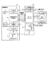
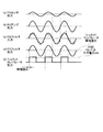
図1は、本発明の第1の実施の形態にかかるモータ駆動装置の構成を示すブロック図、図2はモータ駆動装置が有する回路に生じる信号波形を示す波形図である。以下、モータ駆動装置の構成及び動作について、図1,2を参照して説明する。 FIG. 1 is a block diagram showing a configuration of a motor drive device according to a first embodiment of the present invention, and FIG. 2 is a waveform diagram showing signal waveforms generated in a circuit of the motor drive device. Hereinafter, the configuration and operation of the motor drive device will be described with reference to FIGS.
図1に示すモータ駆動装置は、DCブラシレスモータを用いたメインモータ1と、モータ制御回路を設けた制御基板12と、モータ駆動回路を設けた駆動基板13とを備えている。
The motor drive device shown in FIG. 1 includes a
制御基板12は、画像形成装置の主制御回路用の基板(第1の基板)で、その一部がモータ制御回路を構成する。モータ制御回路は、演算手段として機能するASIC(Application Specific Integrated Circuit)11、ノイズ除去手段として機能するFGフィルタ4、デジタル信号生成手段として機能するシュミットコンパレータ3、フィルタ8を備えている。ASIC11は、デジタル信号の入出力が可能に構成され、デジタル処理を行う。
The
駆動基板13は、制御基板12上には無く、他の基板上もしくは独立した基板として配設されている。駆動基板13内には、FGセンサ14出力用の増幅手段としてのFGアンプ2と、ホール素子15出力用の増幅器としてのホール素子アンプ9が設けられている。なお、ホール素子15は、本発明の課題と直接関係が無いので、以下の記載では、説明を省略する。
The
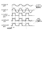
FGセンサ14は、多極着磁されたメインモータ1のロータ磁石と、その着磁面に対向して円形に配置された矩形状のコイルパターンから構成されている。モータ駆動時に、ロータが回転すると、コイルパターンには電圧が誘起され、FGセンサ14からは、図2の(a)の信号波形に示すように、モータの回転速度に応じた周波数の正弦波状の信号が出力される。このFGセンサ出力がアナログ回転周波数(FG)信号に相当する。
The
FGセンサ出力は、微弱な信号であるため、駆動基板13内のFGアンプ2によって増幅された後、アナログ信号のまま、フィードバック信号として制御基板12へ出力される。図2の(b)は、増幅後のFGアンプ2の出力を示す。本実施の形態では、図2の(b)に示す増幅後のアナログ信号が制御基板12へフィードバックされる。なお、先に従来例として図12に示した回路では、アナログ−デジタル変換(以下「A/D変換」と記す)手段としてのシュミットコンパレータ3が駆動基板13のモータ駆動回路内に設けられており、A/D変換後の矩形状のデジタル信号が制御基板12へ出力されている。
Since the FG sensor output is a weak signal, it is amplified by the
フィードバックされるアナログ信号を受取る制御基板12に入力されるFGセンサ信号は、別回路基板に設けられた駆動基板13から制御基板12までの伝送線路上において外来ノイズの影響を受け、図2の(c)の信号波形に示すように、制御基板12のモータ制御回路に入力される信号には、高周波の外来ノイズが重畳される。
The FG sensor signal input to the
そこで、制御基板12上にFGフィルタ4を設け、入力アナログFG信号を先ずこのFGフィルタ4を通すことにより、ノイズを除去する。図2の(d)は、FGフィルタ4を通した後のアナログFG信号出力を示す。ノイズの除去された後のFG信号は、シュミットコンパレータ3に出力される。なお、先に従来例として図12に示した回路では、FGセンサ14のアナログ出力信号をデジタル信号に変換してからノイズ除去を行うため、波形鈍りが発生し、ASIC11のHレベル入力電圧のmin値によって時間遅れが発生する(図13(e)、参照)が、本実施の形態では、アナログ信号のままの状態でノイズ除去を行うため波形鈍りが発生しない。
Therefore, the
なお、本実施の形態では、FGフィルタ4として、ローパスフィルタを用いる例を示すが、ローパスフィルタ以外に、バンドパスフィルタ等のフィルタやFIR(Finite Impulse Response)フィルタやIIR(Infinite Impulse Response)フィルタ等のデジタルフィルタを採用することによっても実施し得る。
In the present embodiment, an example in which a low pass filter is used as the
ノイズの除去された後のアナログFG信号の入力を受けるシュミットコンパレータ3は、設定された閾値により、A/D変換処理し、得られる矩形波信号をデジタル信号の処理が可能なASIC11に出力する。図2の(e)は、シュミットコンパレータ3において、図2の(d)に示すアナログFG信号に対し設定された閾値により、A/D変換処理し、得られる矩形波出力を示す。
The
ASIC11内では、設定されたモータの目標回転速度に対応する周波数信号がタイマ7によって生成され、駆動基板13からフィードバックされたデジタルFG信号出力と対比される。この処理を行う比較部5では、タイマとFGセンサからの回転周波数(FG)信号を比較し、モータの実際の回転速度を目標速度に合わせるための補正信号が生成される。この補正信号を基に、相励磁信号生成部6においてメインモータ1の各相の励磁信号が決定され、この励磁タイミングを示すPWM(Pulse Width Modulation)等の相励磁信号が駆動基板13へ制御信号として出力される。
In the
駆動基板13内のモータドライバ10がメインモータ1を励磁する電流を供給して駆動するモータ駆動手段に相当し、制御基板12のASIC11から入力される励磁信号を基にメインモータ1に電流が供給され、メインモータ1は、設定された目標速度で回転することとなる。
The
以上のように、本実施の形態では、アナログ信号のままの状態でノイズ除去を行うため波形鈍りが発生せず、シュミットコンパレータ3の閾値電圧による時間遅れのみとなるので、従来例の回路(図12)よりも、メインモータ1の速度変動を認識するまでの時間が短縮され、回転精度の向上を図ることが可能になる。
As described above, in this embodiment, since noise is removed in the state of an analog signal, waveform dullness does not occur, and only a time delay due to the threshold voltage of the
このように本実施の形態によれば、DCブラシレスモータ(メインモータ1)の回転速度に応じたアナログ周波数信号を増幅し、増幅後のアナログ周波数信号に対してノイズ除去を施し、ノイズ除去後のアナログ周波数信号をデジタル変換してデジタル周波数信号を生成することにより、従来のようにデジタル変換された矩形波信号に対してノイズ除去を施した場合に生じる波形鈍りが発生せず、デジタル信号生成手段におけるアナログ−デジタル変換の閾値電圧による時間遅れのみとなるので、従来に比べてDCブラシレスモータ(メインモータ1)の速度変動を認識するまでの時間が短縮され、DCブラシレスモータ(メインモータ1)の回転精度の向上を図ることができる。 As described above, according to the present embodiment, the analog frequency signal corresponding to the rotational speed of the DC brushless motor (main motor 1) is amplified, noise is removed from the amplified analog frequency signal, and the noise is removed. By digitally converting an analog frequency signal to generate a digital frequency signal, the digital signal generating means does not cause waveform dullness that occurs when noise is removed from a digitally converted rectangular wave signal as in the past. Therefore, the time until the speed fluctuation of the DC brushless motor (main motor 1) is recognized is shortened compared to the conventional case, and the time of the DC brushless motor (main motor 1) is reduced. The rotation accuracy can be improved.
また、本実施の形態によれば、演算手段(ASIC11)とモータ駆動手段(モータドライバ10)とはそれぞれ別の基板に搭載されており、ノイズ除去手段(FGフィルタ4)は演算手段(ASIC11)とともに第1の基板(制御基板12)に搭載され、増幅手段(FGフィルタ4)はモータ駆動手段(モータドライバ10)とともに第2の基板(駆動基板13)に搭載されていることにより、モータ駆動手段(モータドライバ10)とともに第2の基板(駆動基板13)に搭載されている増幅手段(FGアンプ2)から演算手段(ASIC11)とともに第1の基板(制御基板12)に搭載されているノイズ除去手段(FGフィルタ4)に対してアナログ周波数信号が出力されるので、従来のようにデジタル変換された矩形波信号に対してノイズ除去を施した場合に生じる波形鈍りが発生せず、デジタル信号生成手段(シュミットコンパレータ3)におけるアナログ−デジタル変換の閾値電圧による時間遅れのみとなるので、従来に比べてDCブラシレスモータ(メインモータ1)の速度変動を認識するまでの時間が短縮され、DCブラシレスモータ(メインモータ1)の回転精度の向上を図ることができるとともに、装置の小型化や低コスト化を図ることができる。 Further, according to the present embodiment, the computing means (ASIC 11) and the motor driving means (motor driver 10) are mounted on different substrates, respectively, and the noise removing means (FG filter 4) is the computing means (ASIC 11). And the amplifying means (FG filter 4) are mounted on the second substrate (drive substrate 13) together with the motor drive means (motor driver 10), thereby driving the motor. Noise mounted on the first board (control board 12) together with the calculation means (ASIC 11) from the amplification means (FG amplifier 2) mounted on the second board (drive board 13) together with the means (motor driver 10) Since an analog frequency signal is output to the removing means (FG filter 4), the digital wave converted to the conventional rectangular wave signal is As a result, there is no waveform dullness that occurs when noise removal is performed, and there is only a time delay due to the threshold voltage of the analog-digital conversion in the digital signal generation means (Schmitt comparator 3). The time until the speed fluctuation of the motor 1) is recognized is shortened, the rotational accuracy of the DC brushless motor (main motor 1) can be improved, and the apparatus can be reduced in size and cost.
[第2の実施の形態]
次に、本発明の第2の実施の形態を図3ないし図7に基づいて説明する。なお、前述した第1の実施の形態と同じ部分は同じ符号で示し説明も省略する。本実施の形態は、FG信号に増幅率の異なる増幅器を選択的に用いることにより、安定した特性を得るようにしたものである。
[Second Embodiment]
Next, a second embodiment of the present invention will be described with reference to FIGS. The same parts as those in the first embodiment described above are denoted by the same reference numerals, and description thereof is also omitted. In the present embodiment, stable characteristics are obtained by selectively using amplifiers having different amplification factors for FG signals.
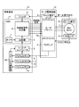
図3は、本発明の第2の実施の形態にかかるモータ駆動装置の構成を示すブロック図である。図3に示すモータ駆動装置の回路と第1の実施の形態で説明したモータ駆動装置(図1)の回路との相違は次の点にある。即ち、第1の実施の形態で説明したモータ駆動装置において単一であったFGアンプ2に代えて、本実施の形態では、FGセンサ14の出力信号に増幅率の異なる増幅器を選択的に用いることを可能にするために、増幅率の異なるFGアンプ(1)2、FGアンプ(2)16、FGアンプ(3)17を備え、又これらのFGアンプ2,16,17のどれを用いるかを選択するFGアンプ選択部18を備えている。なお、FGアンプ選択部18は、制御基板12側に設けられている。すなわち、FGアンプ2,16,17とFGアンプ選択部18とによって増幅率可変手段が構成されている。
FIG. 3 is a block diagram showing the configuration of the motor drive apparatus according to the second embodiment of the present invention. The difference between the circuit of the motor driving apparatus shown in FIG. 3 and the circuit of the motor driving apparatus (FIG. 1) described in the first embodiment is as follows. That is, instead of the
FGセンサ14は、多極着磁されたメインモータ1のロータ磁石と、その着磁面に対向して円形に配置された矩形状のコイルパターンから構成され、こうした構成によって得られる出力は、図4の(A)に示すような特性となる。なお、図4(A)の縦軸はセンサ出力の振幅であり、横軸は時間であり、特性線は低速から高速への変化を示している。図4(A)に示すように、この出力特性は、メインモータ1が低速で回転している状態では振幅が小さく、かつ周波数も小さい状態となり、メインモータ1の速度が上昇するにつれ、振幅と周波数がともに大きくなるという特徴があることを示している。このようなセンサ出力特性のため、センサ出力を受けるFGアンプが単一の場合には、増幅率が一定の状態であるから、FGアンプで増幅された後、図4(A)に示すような特性に従った出力になる。
The
ここで、駆動基板13から制御基板12への伝送線路上でFG信号に重畳する外来ノイズの成分が一定であると仮定すれば、メインモータ1の速度が遅いほどS/N比が低下し相対的に外来ノイズの影響が大きくなる。
Here, if it is assumed that the component of the external noise superimposed on the FG signal on the transmission line from the
そこで、本実施の形態においては、増幅率の異なる複数のFGアンプ(1)2、FGアンプ(2)16、FGアンプ(3)17を駆動基板13に設け、制御基板12に設けたFGアンプ選択部18の選択動作に従い一のFGアンプを選択する。つまり、メインモータ1が低速で回転している際には、FGアンプ選択部18によって増幅率の大きいFGアンプの出力を選択し、メインモータ1の速度が上昇していくにつれて、増幅率のより小さいFGアンプを選択することで、メインモータ1の速度による外来ノイズの影響の違いを無くすことができ、低速時にも安定したFGアンプ出力を得ることができる。
Therefore, in the present embodiment, a plurality of FG amplifiers (1) 2, FG amplifiers (2) 16, and FG amplifiers (3) 17 having different amplification factors are provided on the
図4(B)は、上記の手法によりFGアンプを選択した場合における増幅後のセンサ出力の例を示すもので、同図の縦軸はセンサ出力の振幅であり、横軸は時間である。図4(B)は、増幅前のセンサ出力が図4(A)であった場合に、FGセンサ出力の変化に応じて選択されたFGアンプを用いた結果を示すものである。図4(A)と(B)を対比すると、低速から高速に変化するアンプ出力の振幅が、FGアンプを選択した場合の結果を示す(B)が同レベルに、より近づいていることが理解できよう。 FIG. 4B shows an example of the sensor output after amplification when the FG amplifier is selected by the above method. In FIG. 4B, the vertical axis represents the amplitude of the sensor output, and the horizontal axis represents time. FIG. 4B shows the result of using the FG amplifier selected according to the change of the FG sensor output when the sensor output before amplification is FIG. 4A. 4A and 4B are compared, it is understood that the amplitude of the amplifier output that changes from low speed to high speed is closer to the same level in FIG. 4B, which shows the result when the FG amplifier is selected. I can do it.
このように増幅率のそれぞれ異なる複数の増幅手段(FGアンプ)からDCブラシレスモータ(メインモータ1)の回転速度に応じて一の増幅手段(FGアンプ)を選択することにより、DCブラシレスモータ(メインモータ1)が低速で回転している際には、増幅率の大きい増幅手段(FGアンプ)の出力を選択し、DCブラシレスモータ(メインモータ1)の回転速度が上昇していくにつれて、増幅率のより小さい増幅手段(FGアンプ)を選択することで、DCブラシレスモータ(メインモータ1)の回転速度の違いによる外来ノイズの影響の違いを無くすことができるので、DCブラシレスモータ(メインモータ1)が低速で回転している場合においても安定した増幅手段からの出力を得ることができる。 In this way, by selecting one amplifying means (FG amplifier) from a plurality of amplifying means (FG amplifiers) having different amplification factors according to the rotational speed of the DC brushless motor (main motor 1), a DC brushless motor (main When the motor 1) is rotating at a low speed, the output of the amplification means (FG amplifier) having a large amplification factor is selected, and the amplification factor increases as the rotational speed of the DC brushless motor (main motor 1) increases. By selecting a smaller amplifying means (FG amplifier), the difference in the influence of external noise due to the difference in rotational speed of the DC brushless motor (main motor 1) can be eliminated, so that the DC brushless motor (main motor 1) Even when the motor rotates at a low speed, a stable output from the amplification means can be obtained.
次に、FGアンプ選択部18により増幅率の異なる複数のFGアンプ2,16,17から一のFGアンプを選択する際の選択方式について説明する。
Next, a selection method when the FG
FGセンサ出力の振幅と周波数がメインモータ1の速度に依存する、というFGセンサ14の特性から、FGセンサ出力の振幅もしくは周波数を検知し、その結果により、増幅率の異なる複数のFGアンプ2,16,17から、モータ速度に対応して変動する出力レベルをより近づけるための選択すべきFGアンプを判定することができる。
From the characteristic of the
また、メインモータ1の起動時における「経過時間−回転速度」が所定の動作特性に従うことを前提に、モータ起動からの経過時間によって、適切な切り換えタイミングが推定可能であるから、起動からの経過時間を検知することにより、増幅率の異なる複数のFGアンプ2,16,17から、モータ速度に対応して変動する出力レベルをより近づけるための選択すべきFGアンプを判定することができる。
Further, since it is possible to estimate an appropriate switching timing based on the elapsed time from the start of the motor on the assumption that the “elapsed time-rotation speed” at the start of the
本実施の形態においては、上記した3方式、即ち、
・ FG出力振幅検知方式
・ FG出力周波数検知方式
・ 起動経過時間検知方式
に係わる例を示す。
In the present embodiment, the above three methods, that is,
-FG output amplitude detection method-FG output frequency detection method-Examples related to the startup elapsed time detection method are shown.
(FG出力振幅検知方式)
この方式は、FGセンサ出力の振幅を検知し、検知結果によりFGアンプを選択する方式であるから、FGアンプ選択部18の機能として、FGセンサ14のFG信号出力の振幅を、現在選定し、用いているFGアンプの適否を判断するための基準値に照らして検知し、検知結果に基づき適否を判定する機能を必要とする。
(FG output amplitude detection method)
Since this method is a method of detecting the amplitude of the FG sensor output and selecting the FG amplifier based on the detection result, the amplitude of the FG signal output of the
この判定機能を実現する手段は、ここでは、FGフィルタ4の出力を処理するシュミットコンパレータ3と同様に、FGフィルタ4の出力信号の振幅を予め定めた基準値で閾値処理し、適否を判定する回路(不図示)として備える。
Here, the means for realizing this determination function determines whether or not it is appropriate by thresholding the amplitude of the output signal of the
ここでは、メインモータ1を起動する際に、低速から徐々に速度を上げ、感光体ドラムの周速が一定の安定した回転になるまでの間、FGアンプを選択する動作を行う例を示す。従って、始動時には、FG信号出力の振幅が小さいので、先ず選択するFGアンプとして、増幅率の最も高いFGアンプ(1)2を選定し、徐々に増していく速度に連れて、増幅率のより低いFGアンプ(2)16、FGアンプ(3)17を選定していく、といった方法によって、所期の動作である、低速時にも安定したFGアンプ出力を得ることを可能とするFGアンプの選定をしていく。
Here, an example is shown in which when the
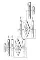
図5は、FG出力振幅検知方式に従いFGアンプを選択する処理動作のフローチャートを示す。なお、この処理フローは、FGアンプ選択部18が行う。
FIG. 5 shows a flowchart of the processing operation for selecting the FG amplifier according to the FG output amplitude detection method. This processing flow is performed by the FG
図5のフローによると、まず、メインモータ1の始動時に、初期条件の設定に従い、最も増幅率の高いFGアンプ(1)2を選択し、FGアンプ(1)2の出力がFGフィルタ4に入力されるようにする(ステップS101)。
According to the flow of FIG. 5, first, at the start of the
その後、メインモータ1を起動し(ステップS102)、定期的にFGフィルタ4の出力振幅をモニターする(ステップS103、104)。図5に例示するフローでは、設定したウエイト時間が10msであるから、10msごとにFGフィルタ出力の振幅をモニターする。ただ、モニター間隔は10msに限られたものではなく、任意に設定し得る。
Thereafter, the
出力振幅のモニターは、現在選択されているFGアンプ(1)2の適否を判断するために予め定めた基準値に照らして、FGフィルタ出力の振幅を検知し、検知結果に基づき適否を判定する。図5の例では、この基準値を4.5Vとし、この値を超えない間は(ステップS103のYES)、FGアンプを変更することなく、モニターを継続する。 The output amplitude monitor detects the amplitude of the FG filter output in light of a predetermined reference value to determine the suitability of the currently selected FG amplifier (1) 2, and judges suitability based on the detection result. . In the example of FIG. 5, this reference value is set to 4.5 V, and monitoring is continued without changing the FG amplifier while this value is not exceeded (YES in step S103).
他方、基準値を超えた場合(ステップS103のNO)、FGアンプ(1)2を用いることは適当ではないと判断し、より低い増幅率のアンプであるFGアンプ(2)16を選定し、FGアンプを切換える(ステップS105)。 On the other hand, if the reference value is exceeded (NO in step S103), it is determined that it is not appropriate to use the FG amplifier (1) 2, and the FG amplifier (2) 16 which is an amplifier having a lower amplification factor is selected. The FG amplifier is switched (step S105).
FGアンプ(2)16に切換えると、アンプの増幅率が低下するため、切換えた直後のFGフィルタ4の出力振幅も減少する。その後、以前と同様にFGフィルタ4の出力振幅をモニターし続ける(ステップS106、107)。即ち、本例では、モニターのウエイト時間が10msに設定され、アンプの適否を判断するために予め定めた基準値を4.5Vとしているので、FGアンプを切換えても、条件の変更は無い。
Switching to the FG amplifier (2) 16 reduces the amplification factor of the amplifier, so the output amplitude of the
再び、FGフィルタ4の出力振幅をモニターし、基準値を超えない間は(ステップS106のYES)、アンプを変更することなく、モニターを継続する。
Again, the output amplitude of the
他方、基準値を超えた場合(ステップS106のNO)、FGアンプ(2)16を用いることは適当ではないと判断し、より低い増幅率のアンプであるFGアンプ(3)17を選定し、アンプを切換える(ステップS108)。 On the other hand, if the reference value is exceeded (NO in step S106), it is determined that it is not appropriate to use the FG amplifier (2) 16, and the FG amplifier (3) 17 which is an amplifier having a lower amplification factor is selected. The amplifier is switched (step S108).
上記のような選択動作によりFGアンプを切換えることにより、安定したFGアンプ出力を得て、FGフィルタ4に出力することができる。
By switching the FG amplifier by the selection operation as described above, a stable FG amplifier output can be obtained and output to the
このように、DCブラシレスモータ(メインモータ1)の回転速度に依存するアナログ周波数信号の振幅値に応じて増幅率を可変とすることにより、モータ起動時には、アナログ周波数信号の振幅が小さいので、先ず増幅率の最も大きい増幅手段(FGアンプ)を選定し、徐々に増していく速度に連れて、増幅率の小さい増幅手段(FGアンプ)を選定していくことで、DCブラシレスモータ(メインモータ1)が低速で回転している場合においても安定した増幅手段(FGアンプ)からの出力を得ることができる。 Thus, by making the amplification factor variable according to the amplitude value of the analog frequency signal that depends on the rotational speed of the DC brushless motor (main motor 1), the amplitude of the analog frequency signal is small when the motor is started. The DC brushless motor (main motor 1) is selected by selecting the amplifying means (FG amplifier) having the largest amplification factor and selecting the amplifying means (FG amplifier) having a small amplification factor as the speed increases gradually. ) Is rotating at a low speed, a stable output from the amplifying means (FG amplifier) can be obtained.
(FG出力周波数検知方式)
この方式は、FGセンサ出力の周波数を検知し、検知結果によりFGアンプを選択する方式であるから、FGアンプ選択部18の機能として、FGセンサ14のFG信号出力の周波数を、現在選定し、用いているFGアンプの適否を判断するための基準値に照らして検知し、検知結果に基づき適否を判定する機能を必要とする。
(FG output frequency detection method)
This method is a method of detecting the frequency of the FG sensor output and selecting the FG amplifier based on the detection result. Therefore, as the function of the FG
この判定機能を実現する手段は、ここでは、FGフィルタ4の出力信号の周波数を求め、得た値を予め定めた基準値で閾値処理し、適否を判定する回路(不図示)として備える。
The means for realizing this determination function is provided as a circuit (not shown) for determining the suitability by obtaining the frequency of the output signal of the
ここでは、メインモータ1を起動する際に、低速から徐々に速度を上げ、感光体ドラムの周速が一定の安定した回転になるまでの間、FGアンプを選択する動作を行う例を示す。従って、始動時には、FG信号出力の周波数が低く、即ち振幅が小さい(図4(A)の説明、参照)ので、先ず選択するFGアンプとして、増幅率の最も高いFGアンプ(1)2を選定し、徐々に増していく速度に連れて、周波数が増し、即ち振幅が大きくなるので、増幅率のより低いFGアンプ(2)16、FGアンプ(3)17を選定していく、といった方法によって、初期の動作である、低速時にも安定したFGアンプ出力を得ることを可能とするFGアンプの選定をしていく。
Here, an example is shown in which when the
図6は、FG出力周波数検知方式に従いFGアンプを選択する処理動作のフローチャートを示す。なお、この処理フローは、FGアンプ選択部18が行う。
FIG. 6 shows a flowchart of a processing operation for selecting an FG amplifier according to the FG output frequency detection method. This processing flow is performed by the FG
図6のフローによると、まず、モータの始動時に、初期条件の設定に従い、最も増幅率の高いFGアンプ(1)2を選択し、FGアンプ(1)2の出力がFGフィルタ4に入力されるようにする(ステップS201)。
According to the flow of FIG. 6, first, at the start of the motor, the FG amplifier (1) 2 having the highest gain is selected according to the initial condition setting, and the output of the FG amplifier (1) 2 is input to the
その後、メインモータ1を起動し(ステップS202)、定期的にFGフィルタ4の出力の周波数をモニターする(ステップS203、204)。図6に例示するフローでは、設定したウエイト時間が10msであるから、10msごとにFGフィルタ出力の周波数をモニターする。ただ、モニター間隔は10msに限られたものではなく、任意に設定し得る。
Thereafter, the
出力周波数のモニターは、現在選択されているFGアンプ(1)2の適否を判断するために予め定めた基準値に照らして、FGフィルタ出力の周波数を検知し、検知結果に基づき適否を判定する。図6の例では、この基準値を100Hzとし、この値を超えない間は(ステップS203のYES)、FGアンプ(1)2を変更することなく、モニターを継続する。 The output frequency monitor detects the frequency of the FG filter output in light of a predetermined reference value in order to determine the suitability of the currently selected FG amplifier (1) 2, and judges the suitability based on the detection result. . In the example of FIG. 6, this reference value is set to 100 Hz, and monitoring is continued without changing the FG amplifier (1) 2 while the reference value is not exceeded (YES in step S203).
他方、基準値を超えた場合(ステップS203のNO)、FGアンプ(1)2を用いることは適当ではないと判断し、より低い増幅率のアンプであるFGアンプ(2)16を選定し、FGアンプを切換える(ステップS205)。 On the other hand, if the reference value is exceeded (NO in step S203), it is determined that it is not appropriate to use the FG amplifier (1) 2, and the FG amplifier (2) 16 which is an amplifier having a lower amplification factor is selected. The FG amplifier is switched (step S205).
FGアンプ(2)16に切換えると、アンプの増幅率が低下するため、切換えた直後のFGフィルタ4の出力振幅も減少する。その後、引続いてFGフィルタ4の出力周波数をモニターする(ステップS206、207)。ただ、出力周波数をモニターする場合、FGアンプが切換わり、出力振幅は減少しても、出力周波数はそのまま増え続ける。従って、適否を判定する基準値を、速度の上昇により再び出力振幅が大きくなりすぎないように、この出力振幅に対応する出力周波数とする。本例では、この値を500Hzと設定する。
Switching to the FG amplifier (2) 16 reduces the amplification factor of the amplifier, so the output amplitude of the
新たに設定した適否を判定する基準値(500Hz)で、再びFGフィルタ4の出力周波数をモニターし、基準値を超えない間は(ステップS206のYES)、FGアンプを変更することなく、モニターを継続する。
The output frequency of the
他方、基準値を超えた場合(ステップS206のNO)、FGアンプ(2)16を用いることは適当ではないと判断し、より低い増幅率のアンプであるFGアンプ(3)17を選定し、アンプを切換える(ステップS208)。 On the other hand, if the reference value is exceeded (NO in step S206), it is determined that it is not appropriate to use the FG amplifier (2) 16, and the FG amplifier (3) 17 which is an amplifier having a lower amplification factor is selected. The amplifier is switched (step S208).
上記のような選択動作によりFGアンプを切換えることにより、安定したFGアンプ出力を得て、FGフィルタ4に出力することができる。
By switching the FG amplifier by the selection operation as described above, a stable FG amplifier output can be obtained and output to the
このように、DCブラシレスモータ(メインモータ1)の回転速度に依存するアナログ周波数信号の周波数に応じて増幅率を可変とすることにより、モータ起動時には、アナログ周波数信号の周波数が低く、即ち振幅が小さいので、先ず増幅率の最も大きい増幅手段(FGアンプ)を選定し、徐々に増していく速度に連れて、周波数が増し、即ち振幅が大きくなるので、増幅率の小さい増幅手段(FGアンプ)を選定していくことで、DCブラシレスモータ(メインモータ1)が低速で回転している場合においても安定した増幅手段(FGアンプ)からの出力を得ることができる。 Thus, by making the amplification factor variable according to the frequency of the analog frequency signal that depends on the rotational speed of the DC brushless motor (main motor 1), the frequency of the analog frequency signal is low, that is, the amplitude is low when the motor is started. Since it is small, the amplification means (FG amplifier) having the largest amplification factor is first selected, and the frequency increases, that is, the amplitude increases as the speed increases gradually. Therefore, the amplification means (FG amplifier) having a small amplification factor. Thus, even when the DC brushless motor (main motor 1) is rotating at a low speed, a stable output from the amplifying means (FG amplifier) can be obtained.
(起動経過時間検知方式)
この方式は、メインモータ1の起動時における「経過時間−回転速度」が所定の動作特性に従うことを前提に、モータ起動からの経過時間を検知し、検知結果によりFGアンプを選択する方式である。よって、FGアンプ選択部18の機能として、タイマで起動時からの時間を計測し、計測した経過時間を、現在選定して用いているFGアンプの適否を判断するための基準値に照らして検知し、検知結果に基づき適否を判定する機能を必要とする。
(Startup elapsed time detection method)
This method is a method of detecting an elapsed time from the start of the motor and selecting an FG amplifier based on the detection result on the premise that “elapsed time-rotation speed” at the start of the
この判定機能を実現する手段は、ここでは、メインモータ1を起動したタイミングでタイマを初期化し、起動時からの経過時間を求め、得られる経過時間が予め定めた基準時間に達したか、否かを検知することにより、適否を判定する回路(不図示)として備える。
Here, the means for realizing this determination function is to initialize a timer at the timing of starting the
ここでは、メインモータ1を起動する際に、低速から徐々に速度を上げ、感光体ドラムの周速が一定の安定した回転になるまでの間、FGアンプを選択する動作を行う例を示す。従って、始動時には、FG信号出力の振幅が小さいので、先ず選択するFGアンプとして、増幅率の最も高いFGアンプ(1)2を選定し、経過時間とともに徐々に増していく速度に連れて、増幅率のより低いFGアンプ(2)16、FGアンプ(3)17を選定していく、といった方法によって、初期の動作である、低速時にも安定したFGアンプ出力を得ることを可能とするFGアンプの選定をしていく。
Here, an example is shown in which when the
図7は、起動経過時間検知方式に従いFGアンプを選択する処理動作のフローチャートを示す。なお、この処理フローは、FGアンプ選択部18が行う。
FIG. 7 shows a flowchart of the processing operation for selecting the FG amplifier according to the startup elapsed time detection method. This processing flow is performed by the FG
図7のフローによると、まず、メインモータ1の始動時に、初期条件の設定に従い、最も増幅率の高いFGアンプ(1)2を選択し、FGアンプ(1)2の出力がFGフィルタ4に入力されるようにする(ステップS301)。
According to the flow of FIG. 7, first, at the start of the
その後、メインモータ1を起動する(ステップS302)。この時に、メインモータ1の起動時からの経過時間を計測するタイマを初期化することにより、計測を始め、タイマが計測する経過時間が予め設定した基準時間に達したか、否かを定期的にチェックする(ステップS303)。
Thereafter, the
図7に例示するフローでは、最も増幅率の高いFGアンプ(1)2の適否を判断するために設定した基準時間が100msであるから、この時間に達したか、否かをチェックする。ただ、この基準時間は、100msに限られたものではなく、「経過時間−回転速度」動作特性とFGアンプの増幅率との兼ね合いで、任意に設定し得る。 In the flow illustrated in FIG. 7, since the reference time set for determining the suitability of the FG amplifier (1) 2 having the highest amplification factor is 100 ms, it is checked whether or not this time has been reached. However, the reference time is not limited to 100 ms, and can be arbitrarily set in consideration of the “elapsed time-rotation speed” operating characteristic and the amplification factor of the FG amplifier.
基準時間として設定した100msを超えない間は(ステップS303のYES)、アンプを変更することなく、モータ起動時からの経過時間を設定した基準時間によりチェックする動作を継続する。 As long as it does not exceed 100 ms set as the reference time (YES in step S303), the operation of checking the elapsed time from the start of the motor with the set reference time is continued without changing the amplifier.
他方、設定した基準時間を超えた場合(ステップS303のNO)、FGアンプ(1)2を用いることは適当ではないと判断し、より低い増幅率のアンプであるFGアンプ(2)16を選定し、FGアンプを切換える(ステップS304)。 On the other hand, if the set reference time is exceeded (NO in step S303), it is determined that it is not appropriate to use the FG amplifier (1) 2, and the FG amplifier (2) 16 that is an amplifier having a lower amplification factor is selected. Then, the FG amplifier is switched (step S304).
FGアンプ(2)16に切換えると、FGアンプの増幅率が低下するため、切換えた直後のFGフィルタ4の出力振幅は一旦減少するが、その後再び上昇を続ける。
When switching to the FG amplifier (2) 16, the amplification factor of the FG amplifier decreases, so the output amplitude of the
その後、引続いてモータ起動時からの経過時間を設定した基準時間によりチェックする(ステップS305)。ただ、チェックする経過時間はモータ起動時からの経過時間であるから、FGアンプが切換わったところで、FGアンプの適否を判断するために設定した基準時間を変更する。本例では、この値を300msと設定する。 After that, the elapsed time from the start of the motor is checked based on the set reference time (step S305). However, since the elapsed time to be checked is the elapsed time from the start of the motor, the reference time set for judging the suitability of the FG amplifier is changed when the FG amplifier is switched. In this example, this value is set to 300 ms.
新たに設定した適否を判定する基準時間(300ms)で、再び経過時間をチェックし、基準時間を超えない間は(ステップS305のYES)、FGアンプを変更することなく、チェックを継続する。 The elapsed time is checked again at the newly set reference time (300 ms) for determining suitability, and the check is continued without changing the FG amplifier as long as the reference time is not exceeded (YES in step S305).
他方、基準時間を超えた場合(ステップS305のNO)、FGアンプ(2)16を用いることは適当ではないと判断し、より低い増幅率のアンプであるFGアンプ(3)17を選定し、アンプを切換える(ステップS306)。 On the other hand, when the reference time is exceeded (NO in step S305), it is determined that it is not appropriate to use the FG amplifier (2) 16, and the FG amplifier (3) 17 which is an amplifier having a lower amplification factor is selected. The amplifier is switched (step S306).
上記のような選択動作によりFGアンプを切換えることにより、安定したFGアンプ出力を得て、FGフィルタ4に出力することができる。
By switching the FG amplifier by the selection operation as described above, a stable FG amplifier output can be obtained and output to the
このように、DCブラシレスモータ(メインモータ1)の回転速度に依存するDCブラシレスモータ(メインモータ1)の起動からの経過時間に応じて増幅率を可変とすることにより、モータ起動時には、アナログ周波数信号の振幅が小さいので、先ず増幅率の最も大きい増幅手段(FGアンプ)を選定し、経過時間とともに徐々に増していく速度に連れて、増幅率の小さい増幅手段(FGアンプ)を選定していくことで、DCブラシレスモータ(メインモータ1)が低速で回転している場合においても安定した増幅手段(FGアンプ)からの出力を得ることができる。 In this way, by changing the amplification factor according to the elapsed time from the start of the DC brushless motor (main motor 1) depending on the rotational speed of the DC brushless motor (main motor 1), the analog frequency at the time of motor start-up is changed. Since the amplitude of the signal is small, the amplification means (FG amplifier) having the largest amplification factor is selected first, and the amplification means (FG amplifier) having a small amplification factor is selected according to the speed that gradually increases with the elapsed time. Thus, even when the DC brushless motor (main motor 1) is rotating at a low speed, a stable output from the amplifying means (FG amplifier) can be obtained.
このように本実施の形態によれば、デジタル周波数信号の出力レベルを一定に保つように、DCブラシレスモータ(メインモータ1)の回転速度に応じて増幅手段(FGアンプ)における増幅率を可変とすることにより、DCブラシレスモータ(メインモータ1)の回転速度の違いによる外来ノイズの影響の違いを無くすことができるので、DCブラシレスモータ(メインモータ1)が低速で回転している場合においても安定した増幅手段(FGアンプ)からの出力を得ることができる。 As described above, according to the present embodiment, the amplification factor in the amplification means (FG amplifier) can be varied according to the rotational speed of the DC brushless motor (main motor 1) so as to keep the output level of the digital frequency signal constant. By doing so, the difference in the influence of external noise due to the difference in rotational speed of the DC brushless motor (main motor 1) can be eliminated, so that the DC brushless motor (main motor 1) is stable even when rotating at a low speed. The output from the amplified means (FG amplifier) can be obtained.
[第3の実施の形態]
次に、本発明の第3の実施の形態を図8ないし図11に基づいて説明する。なお、前述した第1の実施の形態と同じ部分は同じ符号で示し説明も省略する。本実施の形態は、FG信号に除去できるノイズ周波数の異なるフィルタを選択的に用いることにより、安定した特性を得るようにしたものである。
[Third Embodiment]
Next, a third embodiment of the present invention will be described with reference to FIGS. The same parts as those in the first embodiment described above are denoted by the same reference numerals, and description thereof is also omitted. In this embodiment, stable characteristics are obtained by selectively using filters with different noise frequencies that can be removed from the FG signal.
図8は、本発明の第3の実施の形態にかかるモータ駆動装置の構成を示すブロック図である。図8に示すモータ駆動装置の回路と第1の実施の形態で説明したモータ駆動装置(図1)の回路との相違は次の点にある。即ち、第1の実施の形態で説明したモータ駆動装置において単一であったFGフィルタ4に代えて、本実施の形態では、駆動基板13からフィードバックされてくるFG信号に、除去できるノイズ周波数を異にしたフィルタを選択的に通すことを可能にするために、遮断周波数の異なるFGフィルタ(1)4、FGフィルタ(2)18、FGフィルタ(3)19を備え、又これらのFGフィルタのどれを用いるかを選択するFGフィルタ選択部20を備えている。なお、FGフィルタ選択部20は、制御基板12側に設けられている。すなわち、FGフィルタ4,18,19とFGフィルタ選択部20とによって遮断周波数可変手段が構成されている。
FIG. 8 is a block diagram showing the configuration of the motor drive apparatus according to the third embodiment of the present invention. The difference between the circuit of the motor driving device shown in FIG. 8 and the circuit of the motor driving device (FIG. 1) described in the first embodiment is as follows. That is, instead of the
なお、本実施の形態では、FGフィルタ(1)4、FGフィルタ(2)18、FGフィルタ(3)19として、ローパスフィルタを用いる例を示すが、ローパスフィルタ以外に、バンドパスフィルタ等のフィルタやFIR(Finite Impulse Response)フィルタやIIR(Infinite Impulse Response)フィルタ等のデジタルフィルタを採用することによっても実施し得る。 In this embodiment, an example in which a low-pass filter is used as the FG filter (1) 4, the FG filter (2) 18, and the FG filter (3) 19 is shown. However, in addition to the low-pass filter, a filter such as a band-pass filter is used. It can also be implemented by adopting a digital filter such as an FIR (Finite Impulse Response) filter or an IIR (Infinite Impulse Response) filter.
FGセンサ14の出力特性は、先に、図4(A)を参照して説明したように、メインモータ1が低速で回転している状態では振幅が小さく、かつ周波数も小さい状態となり、メインモータ1の速度が上昇するにつれ、振幅と周波数がともに大きくなるという特徴がある。このようなFGセンサ14の出力特性のため、FGセンサ14からのFG信号を受けるFGフィルタが単一の場合、速度が上昇し、FG信号の周波数が高くなるに連れ、FG信号ノイズ除去効果が低減する傾向が生じる。
As described above with reference to FIG. 4A, the output characteristics of the
そこで、本実施の形態においては、遮断周波数の異なるFGフィルタ(1)4、FGフィルタ(2)18、FGフィルタ(3)19を設け、これらの中からFGフィルタ選択部20の選択動作に従い一のFGフィルタを選択する。つまり、メインモータ1が低速で回転している際には、FGフィルタ選択部20によって遮断周波数の低いFGフィルタを選択し、メインモータ1の速度が上昇していくにつれて、遮断周波数のより高いFGフィルタを選択することで、ノイズ除去効果が低減することなく、メインモータ1の速度に関わらず、正確なFG信号を得ることができる。
Therefore, in the present embodiment, FG filter (1) 4, FG filter (2) 18, and FG filter (3) 19 having different cutoff frequencies are provided, and one of them is selected according to the selection operation of FG
このように、遮断周波数のそれぞれ異なる複数のノイズ除去手段(FGフィルタ)からDCブラシレスモータ(メインモータ1)の回転速度に応じて一のノイズ除去手段(FGフィルタ)を選択することにより、DCブラシレスモータ(メインモータ1)が低速で回転している際には、遮断周波数の低いノイズ除去手段(FGフィルタ)を選択し、DCブラシレスモータ(メインモータ1)の回転速度が上昇していくにつれて、遮断周波数のより高いノイズ除去手段(FGフィルタ)を選択することで、DCブラシレスモータ(メインモータ1)の回転速度が上昇してもノイズ除去効果を低減させないようにすることができるので、DCブラシレスモータ(メインモータ1)が高速で回転している場合においても、確実にノイズ除去が施されたアナログ周波数信号を得ることができる。 Thus, by selecting one noise removing means (FG filter) from a plurality of noise removing means (FG filters) having different cutoff frequencies according to the rotational speed of the DC brushless motor (main motor 1), the DC brushless When the motor (main motor 1) is rotating at a low speed, a noise removing means (FG filter) having a low cutoff frequency is selected, and as the rotational speed of the DC brushless motor (main motor 1) increases, By selecting a noise removal means (FG filter) having a higher cut-off frequency, it is possible to prevent the noise removal effect from being reduced even if the rotational speed of the DC brushless motor (main motor 1) increases. Even when the motor (main motor 1) is rotating at a high speed, noise is reliably removed. It is possible to obtain an analog frequency signal.
次に、FGフィルタ選択部20により遮断周波数の異なる複数のFGフィルタ4,18,19から一のFGフィルタを選択する際の選択方式について説明する。
Next, a selection method when the FG
FGセンサ出力の振幅と周波数がメインモータ1の速度に依存する、というFGセンサの特性から、FGセンサ出力の振幅もしくは周波数を検知し、その結果により、遮断周波数の異なる複数のFGフィルタから、モータ速度が上昇してもノイズ除去効果を低減させないようにするために、選択すべきFGフィルタを判定することができる。
The amplitude or frequency of the FG sensor output is detected from the characteristics of the FG sensor that the amplitude and frequency of the FG sensor output depend on the speed of the
また、メインモータ1の起動時における「経過時間−回転速度」が所定の動作特性に従うことを前提に、モータ起動からの経過時間によって、適切な切り換えタイミングが推定可能であるから、起動からの経過時間を検知することにより、遮断周波数の異なる複数のFGフィルタから、モータ速度に対応して変動するノイズ除去効果を低減させないようにするために、選択すべきFGフィルタを判定することができる。
Further, since it is possible to estimate an appropriate switching timing based on the elapsed time from the start of the motor on the assumption that the “elapsed time-rotation speed” at the start of the
本実施の形態においては、上記した3方式、即ち、
・ FG出力振幅検知方式
・ FG出力周波数検知方式
・ 起動経過時間検知方式
に係わる例を示す。
In the present embodiment, the above three methods, that is,
-FG output amplitude detection method-FG output frequency detection method-Examples related to the startup elapsed time detection method are shown.
(FG出力振幅検知方式)
この方式は、FGセンサ出力の振幅を検知し、検知結果によりFGフィルタを選択する方式であるから、FGフィルタ選択部20の機能として、FGセンサのFG信号出力の振幅を、現在選定し、用いているFGフィルタの適否を判断するための基準値に照らして検知し、検知結果に基づき適否を判定する機能を必要とする。
(FG output amplitude detection method)
Since this method is a method of detecting the amplitude of the FG sensor output and selecting the FG filter based on the detection result, the amplitude of the FG signal output of the FG sensor is currently selected and used as a function of the FG
この判定機能を実現する手段は、ここでは、FGフィルタ出力を処理するシュミットコンパレータ3と同様に、FGフィルタ出力信号の振幅を予め定めた基準値で閾値処理し、適否を判定する回路(不図示)として備える。
Here, the means for realizing the determination function is a circuit (not shown) for determining the suitability by performing threshold processing on the amplitude of the FG filter output signal with a predetermined reference value, like the
ここでは、メインモータ1を起動する際に、低速から徐々に速度を上げ、感光体ドラムの周速が一定の安定した回転になるまでの間、FGフィルタを選択する動作を行う例を示す。従って、始動時には、FG信号出力の振幅が小さいので、先ず選択するFGフィルタとして、遮断周波数の最も低いローパスのFGフィルタ(1)4を選定し、徐々に増していく速度に連れて、遮断周波数のより高いFGフィルタ(2)18、FGフィルタ(3)19を選定していく、といった方法によって、初期の動作である、高速時にもノイズ除去効果を低減させない、安定したFG信号出力を得ることを可能とするFGフィルタの選定をしていく。
Here, an example is shown in which when the
図9は、FG出力振幅検知方式に従いFGフィルタを選択する処理動作のフローチャートを示す。なお、この処理フローは、FGフィルタ選択部20が行う。
FIG. 9 shows a flowchart of a processing operation for selecting an FG filter in accordance with the FG output amplitude detection method. This processing flow is performed by the FG
図9のフローによると、まず、メインモータ1の始動時に、初期条件の設定に従い、遮断周波数の最も低いローパスのFGフィルタ(1)4を選択し、FGアンプ2の入力を受けるようにする(ステップS401)。
According to the flow of FIG. 9, first, when starting the
その後、メインモータ1を起動し(ステップS402)、定期的にFGフィルタ(1)4の出力振幅をモニターする(ステップS403、404)。図9に例示するフローでは、設定したウエイト時間が10msであるから、10msごとにFGフィルタ出力の振幅をモニターする。ただ、モニター間隔は10msに限られたものではなく、任意に設定し得る。
Thereafter, the
出力振幅のモニターは、現在選択されているFGフィルタ(1)4の適否を判断するために予め定めた基準値に照らして、FGフィルタ(1)4の振幅を検知し、検知結果に基づき適否を判定する。図9の例では、この基準値を2Vとし、この値を超えない間は(ステップS403のYES)、フィルタを変更することなく、モニターを継続する。 The output amplitude monitor detects the amplitude of the FG filter (1) 4 in light of a predetermined reference value in order to determine whether the currently selected FG filter (1) 4 is appropriate. Determine. In the example of FIG. 9, this reference value is set to 2V, and monitoring is continued without changing the filter while this value is not exceeded (YES in step S403).
他方、基準値を超えた場合(ステップS403のNO)、FGフィルタ(1)4を用いることは適当ではないと判断し、より高い遮断周波数のローパスフィルタであるFGフィルタ(2)18を選定し、FGフィルタを切換える(ステップS405)。 On the other hand, if the reference value is exceeded (NO in step S403), it is determined that it is not appropriate to use the FG filter (1) 4, and the FG filter (2) 18 which is a low-pass filter having a higher cutoff frequency is selected. The FG filter is switched (step S405).
FGフィルタ(2)18に切換えた後、これまでと同様にFGフィルタの出力振幅をモニターし続ける(ステップS406、407)。ただ、FGフィルタをFGフィルタ(2)18に切換えたので、基準値をFGフィルタ(2)18の適否を判断するために予め定めた基準値に変更する。この例では、今度は、基準値を4Vへと、条件を変更する。即ち、FGフィルタ(2)18は、前のFGフィルタ(1)4の設定は2Vであるから2V〜4Vの間で用いる。 After switching to the FG filter (2) 18, the output amplitude of the FG filter is continuously monitored as before (steps S406 and 407). However, since the FG filter is switched to the FG filter (2) 18, the reference value is changed to a predetermined reference value in order to determine whether the FG filter (2) 18 is appropriate. In this example, this time, the condition is changed to 4V. That is, the FG filter (2) 18 is used between 2V and 4V because the setting of the previous FG filter (1) 4 is 2V.
再び、FGフィルタ(2)18の出力振幅をモニターし、基準値(4V)を超えない間は(ステップS406のYES)、FGフィルタを変更することなく、モニターを継続する。 Again, the output amplitude of the FG filter (2) 18 is monitored, and monitoring is continued without changing the FG filter as long as the reference value (4 V) is not exceeded (YES in step S406).
他方、基準値を超えた場合(ステップS406のNO)、FGフィルタ(2)18を用いることは適当ではないと判断し、さらに高い遮断周波数のローパスフィルタであるFGフィルタ(3)19を選定し、フィルタを切換える(ステップS408)。 On the other hand, if the reference value is exceeded (NO in step S406), it is determined that it is not appropriate to use the FG filter (2) 18, and the FG filter (3) 19 which is a low-pass filter having a higher cutoff frequency is selected. The filter is switched (step S408).
上記のような選択動作によりFGフィルタを切換えることにより、高速時にもノイズ除去効果が低減せず、安定したFG信号出力を得、シュミットコンパレータ3に出力することができる。
By switching the FG filter by the selection operation as described above, the noise removal effect is not reduced even at high speed, and a stable FG signal output can be obtained and output to the
このように、DCブラシレスモータ(メインモータ1)の回転速度に依存するアナログ周波数信号の振幅値に応じて遮断周波数を可変とすることにより、モータ起動時には、アナログ周波数信号の振幅が小さいので、先ず遮断周波数の最も低いノイズ除去手段(FGフィルタ)を選定し、徐々に増していく速度に連れて、遮断周波数のより高いノイズ除去手段(FGフィルタ)を選定していくことで、DCブラシレスモータ(メインモータ1)が高速で回転している場合においても、確実にノイズ除去が施されたアナログ周波数信号を得ることができる。 Thus, by making the cut-off frequency variable according to the amplitude value of the analog frequency signal that depends on the rotational speed of the DC brushless motor (main motor 1), the amplitude of the analog frequency signal is small when the motor is started. The DC brushless motor (FG filter) is selected by selecting the noise removing means (FG filter) having the lowest cutoff frequency and selecting the noise removing means (FG filter) having a higher cutoff frequency as the speed gradually increases. Even when the main motor 1) rotates at high speed, an analog frequency signal from which noise has been reliably removed can be obtained.
(FG出力周波数検知方式)
この方式は、FGセンサ出力の周波数を検知し、検知結果によりFGフィルタを選択する方式であるから、FGフィルタ選択部20の機能として、FGセンサのFG信号出力の周波数を、現在選定して用いているFGフィルタの適否を判断するための基準値に照らして検知し、検知結果に基づき適否を判定する機能を必要とする。
(FG output frequency detection method)
In this method, the frequency of the FG sensor output is detected, and the FG filter is selected based on the detection result. Therefore, as the function of the FG
この判定機能を実現する手段は、ここでは、FGフィルタ4の出力信号の周波数を求め、得た値を予め定めた基準値で閾値処理し、適否を判定する回路(不図示)として備える。
The means for realizing this determination function is provided as a circuit (not shown) for determining the suitability by obtaining the frequency of the output signal of the
ここでは、メインモータ1を起動する際に、低速から徐々に速度を上げ、感光体ドラムの周速が一定の安定した回転になるまでの間、FGフィルタを選択する動作を行う例を示す。従って、始動時には、FG信号出力の周波数が低く、振幅が小さい(図4(A)の説明を参照)ので、先ず選択するFGフィルタとして、遮断周波数の最も低いローパスのFGフィルタ(1)4を選定し、徐々に増していく速度に連れて、周波数が増し、即ち振幅が大きくなるので、遮断周波数のより高いローパスのFGフィルタ(2)18、FGフィルタ(3)19を選定していく、といった方法によって、初期の動作である、高速時にもノイズ除去効果を低減させない、安定したFG信号出力を得ることを可能とするFGフィルタの選定をしていく。
Here, an example is shown in which when the
図10は、FG出力周波数検知方式に従いFGフィルタを選択する処理動作のフローチャートを示す。なお、この処理フローは、FGフィルタ選択部20が行う。
FIG. 10 shows a flowchart of a processing operation for selecting an FG filter in accordance with the FG output frequency detection method. This processing flow is performed by the FG
図10のフローによると、まず、メインモータ1の始動時に、初期条件の設定に従い、遮断周波数の最も低いローパスのFGフィルタ(1)4を選択し、FGアンプ2の出力がFGフィルタ(1)4に入力されるようにする(ステップS501)。
According to the flow of FIG. 10, first, when the
その後、モータを起動し(ステップS502)、定期的にFGフィルタ4の出力の周波数をモニターする(ステップS503、504)。図10に例示するフローでは、設定したウエイト時間が10msであるから、10msごとにFGフィルタ出力の周波数をモニターする。ただ、モニター間隔は10msに限られたものではなく、任意に設定し得る。
Thereafter, the motor is started (step S502), and the frequency of the output of the
出力周波数のモニターは、現在選択されているFGフィルタ(1)4の適否を判断するために予め定めた基準値に照らして、FGフィルタ出力の周波数を検知し、検知結果に基づき適否を判定する。図10の例では、この基準値を100Hzとし、この値を超えない間は(ステップS503のYES)、フィルタを変更することなく、モニターを継続する。 The output frequency monitor detects the frequency of the FG filter output in accordance with a predetermined reference value to determine the suitability of the currently selected FG filter (1) 4, and judges the suitability based on the detection result. . In the example of FIG. 10, this reference value is set to 100 Hz, and monitoring is continued without changing the filter while this value is not exceeded (YES in step S503).
他方、基準値を超えた場合(ステップS503のNO)、FGフィルタ(1)4を用いることは適当ではないと判断し、より高い遮断周波数のローパスフィルタであるFGフィルタ(2)18を選定し、FGフィルタを切換える(ステップS505)。 On the other hand, if the reference value is exceeded (NO in step S503), it is determined that it is not appropriate to use the FG filter (1) 4, and the FG filter (2) 18 that is a low-pass filter having a higher cutoff frequency is selected. The FG filter is switched (step S505).
FGフィルタ(2)18に切換えた後、これまでと同様にFGフィルタ(2)18の出力周波数をモニターし続ける(ステップS506、507)。ただ、FGフィルタをFGフィルタ(2)18に切換えたので、基準値をFGフィルタ(2)18の適否を判断するために予め定めた基準値に変更する。この例では、今度は、基準値を500Hzへと、条件を変更する。即ち、FGフィルタ(2)18は、前のFGフィルタ(1)4の設定は100Hzであるから100Hz〜500Hzの間で用いる。 After switching to the FG filter (2) 18, the output frequency of the FG filter (2) 18 is continuously monitored as before (steps S506 and S507). However, since the FG filter is switched to the FG filter (2) 18, the reference value is changed to a predetermined reference value in order to determine whether the FG filter (2) 18 is appropriate. In this example, this time, the condition is changed to the reference value of 500 Hz. That is, the FG filter (2) 18 is used between 100 Hz and 500 Hz because the setting of the previous FG filter (1) 4 is 100 Hz.
再び、FGフィルタ(2)18の出力周波数をモニターし、基準値(500Hz)を超えない間は(ステップS506のYES)、FGフィルタを変更することなく、モニターを継続する。 Again, the output frequency of the FG filter (2) 18 is monitored, and monitoring is continued without changing the FG filter as long as the reference value (500 Hz) is not exceeded (YES in step S506).
他方、基準値を超えた場合(ステップS506のNO)、FGフィルタ(2)18を用いることは適当ではないと判断し、さらに高い遮断周波数のローパスフィルタであるFGフィルタ(3)19を選定し、FGフィルタを切換える(ステップS508)。 On the other hand, if the reference value is exceeded (NO in step S506), it is determined that it is not appropriate to use the FG filter (2) 18, and the FG filter (3) 19 which is a low-pass filter having a higher cutoff frequency is selected. The FG filter is switched (step S508).
上記のような選択動作によりFGフィルタを切換えることにより、高速時にもノイズ除去効果が低減せず、安定したFG信号出力を得、シュミットコンパレータ3に出力することができる。
By switching the FG filter by the selection operation as described above, the noise removal effect is not reduced even at high speed, and a stable FG signal output can be obtained and output to the
このように、DCブラシレスモータ(メインモータ1)の回転速度に依存するアナログ周波数信号の周波数に応じて遮断周波数を可変とすることにより、モータ起動時には、アナログ周波数信号の周波数が低く、振幅が小さいので、先ず遮断周波数の最も低いノイズ除去手段(FGフィルタ)を選定し、徐々に増していく速度に連れて、周波数が増し、即ち振幅が大きくなるので、遮断周波数のより高いノイズ除去手段(FGフィルタ)を選定していくことで、DCブラシレスモータ(メインモータ1)が高速で回転している場合においても、確実にノイズ除去が施されたアナログ周波数信号を得ることができる。 Thus, by making the cut-off frequency variable according to the frequency of the analog frequency signal that depends on the rotational speed of the DC brushless motor (main motor 1), the frequency of the analog frequency signal is low and the amplitude is small when the motor is started. Therefore, the noise removing means (FG filter) having the lowest cutoff frequency is first selected, and the frequency increases, that is, the amplitude increases with the rate of gradually increasing. Therefore, the noise removing means (FG having a higher cutoff frequency). By selecting the filter, it is possible to obtain an analog frequency signal from which noise has been reliably removed even when the DC brushless motor (main motor 1) is rotating at high speed.
(起動経過時間検知方式)
この方式は、メインモータ1の起動時における「経過時間―回転速度」が所定の動作特性に従うことを前提に、モータ起動からの経過時間を検知し、検知結果によりFGフィルタを選択する方式である。よって、FGフィルタ選択部20の機能として、タイマで起動時からの時間を計測し、計測した経過時間を、現在選定して用いているFGフィルタの適否を判断するための基準値に照らして検知し、検知結果に基づき適否を判定する機能を必要とする。
(Startup elapsed time detection method)
This method is a method of detecting the elapsed time from the start of the motor and selecting the FG filter based on the detection result on the premise that the “elapsed time-rotation speed” at the start of the
この判定機能を実現する手段は、ここでは、メインモータ1を起動したタイミングでタイマを初期化し、起動時からの経過時間を求め、得られる経過時間が予め定めた基準時間に達したか、否かを検知することにより、適否を判定する回路(不図示)として備える。
Here, the means for realizing this determination function is to initialize a timer at the timing of starting the
ここでは、メインモータ1を起動する際に、低速から徐々に速度を上げ、感光体ドラムの周速が一定の安定した回転になるまでの間、FGフィルタを選択する動作を行う例を示す。従って、始動時には、FG信号出力の周波数が低く、振幅が小さい(図4(A)の説明を参照)ので、先ず選択するFGフィルタとして、遮断周波数の最も低いローパスのFGフィルタ(1)4を選定し、徐々に増していく速度に連れて、周波数が増し、即ち振幅が大きくなるので、遮断周波数のより高いローパスのFGフィルタ(2)18、FGフィルタ(3)19を選定していく、といった方法によって、初期の動作である、高速時にもノイズ除去効果を低減させない、安定したFG信号出力を得ることを可能とするFGフィルタの選定をしていく。
Here, an example is shown in which when the
図11は、起動経過時間検知方式に従いFGフィルタを選択する処理動作のフローチャートを示す。なお、この処理フローは、FGフィルタ選択部20が行う。
FIG. 11 shows a flowchart of the processing operation for selecting the FG filter according to the startup elapsed time detection method. This processing flow is performed by the FG
図11のフローによると、まず、モータの始動時に、初期条件の設定に従い、遮断周波数の最も低いローパスのFGフィルタ(1)4を選択し、FGアンプ2の出力がFGフィルタ(1)4に入力されるようにする(ステップS601)。
According to the flow of FIG. 11, first, at the start of the motor, the low-pass FG filter (1) 4 having the lowest cutoff frequency is selected according to the initial condition setting, and the output of the
その後、メインモータ1を起動する(ステップS602)。この時に、メインモータ1の起動時からの経過時間を計測するタイマを初期化することにより、計測を始め、タイマが計測する経過時間が予め設定した基準時間に達したか、否かを定期的にチェックする(ステップS603)。
Thereafter, the
図11に例示するフローでは、最も遮断周波数の低いローパスのFGフィルタ(1)4の適否を判断するために設定した基準時間が100msであるから、この時間に達したか、否かをチェックする。ただ、この基準時間は、100msに限られたものではなく、「経過時間−回転速度」動作特性とFGフィルタのフィルタ特性との兼ね合いで、任意に設定し得る。 In the flow illustrated in FIG. 11, since the reference time set for determining whether the low-pass FG filter (1) 4 having the lowest cutoff frequency is appropriate is 100 ms, it is checked whether or not this time has been reached. . However, the reference time is not limited to 100 ms, and can be arbitrarily set in consideration of the “elapsed time-rotation speed” operation characteristic and the filter characteristic of the FG filter.
基準時間として設定した100msを超えない間は(ステップS603のYES)、フィルタを変更することなく、モータ起動時からの経過時間を設定した基準時間によりチェックする動作を継続する。 As long as it does not exceed 100 ms set as the reference time (YES in step S603), the operation of checking the elapsed time from the start of the motor according to the set reference time is continued without changing the filter.
他方、設定した基準時間を超えた場合(ステップS603のNO)、FGフィルタ(1)4を用いることは適当ではないと判断し、より遮断周波数の高いローパスのFGフィルタ(2)18を選定し、フィルタを切換える(ステップS604)。 On the other hand, if the set reference time is exceeded (NO in step S603), it is determined that it is not appropriate to use the FG filter (1) 4, and the low-pass FG filter (2) 18 having a higher cutoff frequency is selected. The filter is switched (step S604).
FGフィルタ(2)18に切換えた後、引続いてモータ起動時からの経過時間を設定した基準時間によりチェックする(ステップS605)。ただ、チェックする経過時間はモータ起動時からの経過時間であるから、FGフィルタが切換わったところで、FGフィルタの適否を判断するために設定した基準時間を変更する。本例では、この値を300msと設定する。 After switching to the FG filter (2) 18, the elapsed time from the start of the motor is subsequently checked based on the set reference time (step S605). However, since the elapsed time to be checked is the elapsed time from the start of the motor, the reference time set for judging the suitability of the FG filter is changed when the FG filter is switched. In this example, this value is set to 300 ms.
新たに設定した適否を判定する基準時間(300ms)で、再び経過時間をチェックし、基準時間を超えない間は(ステップS605のYES)、FGフィルタを変更することなく、チェックを継続する。 The elapsed time is checked again at the newly set reference time (300 ms) for determining suitability, and the check is continued without changing the FG filter as long as the reference time is not exceeded (YES in step S605).
他方、基準時間を超えた場合(ステップS605のNO)、FGフィルタ(2)18を用いることは適当ではないと判断し、さらに遮断周波数の高いローパスのFGフィルタ(3)19を選定し、FGフィルタを切換える(ステップS606)。 On the other hand, if the reference time is exceeded (NO in step S605), it is determined that it is not appropriate to use the FG filter (2) 18, and a low-pass FG filter (3) 19 having a higher cut-off frequency is selected. The filter is switched (step S606).
上記のような選択動作によりFGフィルタを切換えることにより、高速時にもノイズ除去効果が低減せず、安定したFG信号出力を得て、シュミットコンパレータ3に出力することができる。
By switching the FG filter by the selection operation as described above, the noise removal effect is not reduced even at high speed, and a stable FG signal output can be obtained and output to the
このように、DCブラシレスモータ(メインモータ1)の回転速度に依存するDCブラシレスモータ(メインモータ1)の起動からの経過時間に応じて遮断周波数を可変とすることにより、モータ起動時には、アナログ周波数信号の周波数が低く、振幅が小さいので、先ず遮断周波数の最も低いノイズ除去手段(FGフィルタ)を選定し、徐々に増していく速度に連れて、周波数が増し、即ち振幅が大きくなるので、遮断周波数のより高いノイズ除去手段(FGフィルタ)を選定していくことで、DCブラシレスモータ(メインモータ1)が高速で回転している場合においても、確実にノイズ除去が施されたアナログ周波数信号を得ることができる。 In this way, by making the cut-off frequency variable according to the elapsed time from the start of the DC brushless motor (main motor 1) depending on the rotational speed of the DC brushless motor (main motor 1), the analog frequency at the time of motor start-up Since the signal frequency is low and the amplitude is small, the noise removal means (FG filter) having the lowest cutoff frequency is selected first, and the frequency increases, that is, the amplitude increases as the speed increases gradually. By selecting noise removal means (FG filter) with a higher frequency, even if the DC brushless motor (main motor 1) is rotating at high speed, an analog frequency signal from which noise has been reliably removed can be obtained. Obtainable.
このように本実施の形態によれば、増幅後のアナログ周波数信号に対するノイズ除去効果を一定に保つように、DCブラシレスモータ(メインモータ1)の回転速度に応じてノイズ除去手段(FGフィルタ)における遮断周波数を可変とすることにより、DCブラシレスモータ(メインモータ1)の回転速度が上昇してもノイズ除去効果を低減させないようにすることができるので、DCブラシレスモータ(メインモータ1)が高速で回転している場合においても、確実にノイズ除去が施されたアナログ周波数信号を得ることができる。 As described above, according to the present embodiment, in the noise removing means (FG filter) according to the rotational speed of the DC brushless motor (main motor 1) so as to keep the noise removing effect on the amplified analog frequency signal constant. By making the cut-off frequency variable, it is possible to prevent the noise removal effect from being reduced even if the rotational speed of the DC brushless motor (main motor 1) increases, so that the DC brushless motor (main motor 1) can operate at high speed. Even in the case of rotation, an analog frequency signal from which noise has been reliably removed can be obtained.
1 DCブラシレスモータ
2,16,17 増幅手段
3 デジタル信号生成手段
4,18,19 ノイズ除去手段
10 モータ駆動手段
11 演算手段
12 第1の基板
13 第2の基板
DESCRIPTION OF
Claims (12)
前記第2の基板は、
DCブラシレスモータの回転速度に応じたアナログ周波数信号を増幅する増幅手段を備え、
前記第1の基板は、
増幅後のアナログ周波数信号に対してノイズ除去を施すノイズ除去手段と、
ノイズ除去後のアナログ周波数信号をデジタル変換してデジタル周波数信号を生成するデジタル信号生成手段と、
前記DCブラシレスモータが設定速度で駆動するように、前記デジタル周波数信号に基づいて前記DCブラシレスモータの各相の電流制御量を演算する演算手段と、
を備え、
前記第2の基板はさらに、前記電流制御量に基づいて前記DCブラシレスモータを駆動するモータ駆動手段を備える、
ことを特徴とするモータ駆動装置。 A motor drive device having at least a first substrate and a second substrate,
The second substrate is
Amplifying means for amplifying an analog frequency signal according to the rotational speed of the DC brushless motor,
The first substrate is
Noise removing means for removing noise from the amplified analog frequency signal;
Digital signal generating means for digitally converting the analog frequency signal after noise removal to generate a digital frequency signal;
Arithmetic means for calculating a current control amount of each phase of the DC brushless motor based on the digital frequency signal so that the DC brushless motor is driven at a set speed;
With
The second substrate further includes motor driving means for driving the DC brushless motor based on the current control amount .
The motor drive device characterized by the above-mentioned.
ことを特徴とする請求項1記載のモータ駆動装置。 An amplification factor varying means for varying the amplification factor in the amplification means according to the rotational speed of the DC brushless motor so as to keep the output level of the digital frequency signal constant;
The motor driving apparatus according to claim 1.
ことを特徴とする請求項2記載のモータ駆動装置。 The amplification factor varying means selects one amplification means according to the rotational speed of the DC brushless motor from the plurality of amplification means having different amplification factors.
The motor driving apparatus according to claim 2, wherein
ことを特徴とする請求項2または3記載のモータ駆動装置。 The gain variable means makes the gain variable according to the amplitude value of the analog frequency signal depending on the rotational speed of the DC brushless motor.
The motor driving apparatus according to claim 2 or 3, wherein
ことを特徴とする請求項2または3記載のモータ駆動装置。 The gain variable means makes the gain variable according to the frequency of the analog frequency signal that depends on the rotational speed of the DC brushless motor.
The motor driving apparatus according to claim 2 or 3, wherein
ことを特徴とする請求項2または3記載のモータ駆動装置。 The gain variable means makes the gain variable according to the elapsed time from the start of the DC brushless motor depending on the rotational speed of the DC brushless motor.
The motor driving apparatus according to claim 2 or 3, wherein
前記増幅後のアナログ周波数信号に対するノイズ除去効果を一定に保つように、前記DCブラシレスモータの回転速度に応じて前記ノイズ除去手段における遮断周波数を可変とする遮断周波数可変手段を更に備える、
ことを特徴とする請求項1記載のモータ駆動装置。 The first substrate is
Further comprising cutoff frequency variable means for varying the cutoff frequency in the noise removing means according to the rotational speed of the DC brushless motor so as to keep the noise removal effect on the amplified analog frequency signal constant.
The motor driving apparatus according to claim 1.
ことを特徴とする請求項7記載のモータ駆動装置。 The cutoff frequency varying means selects one of the noise removing means according to the rotational speed of the DC brushless motor from the plurality of noise removing means having different cutoff frequencies.
The motor driving apparatus according to claim 7.
ことを特徴とする請求項7または8記載のモータ駆動装置。 The cutoff frequency variable means makes the cutoff frequency variable according to the amplitude value of the analog frequency signal depending on the rotational speed of the DC brushless motor.
9. The motor driving apparatus according to claim 7 or 8, wherein
ことを特徴とする請求項7または8記載のモータ駆動装置。 The cutoff frequency variable means makes the cutoff frequency variable according to the frequency of the analog frequency signal that depends on the rotational speed of the DC brushless motor.
9. The motor driving apparatus according to claim 7 or 8, wherein
ことを特徴とする請求項7または8記載のモータ駆動装置。 The cut-off frequency variable means makes the cut-off frequency variable according to the elapsed time from the start of the DC brushless motor depending on the rotation speed of the DC brushless motor.
9. The motor driving apparatus according to claim 7 or 8, wherein
前記像担持体への画像形成処理を行うための動作部と、An operation unit for performing an image forming process on the image carrier;
前記像担持体および動作部を駆動するDCブラシレスモータと、A DC brushless motor for driving the image carrier and the operation unit;
少なくとも第1の基板と第2の基板とを有するモータ駆動装置と、A motor drive device having at least a first substrate and a second substrate;
を備え、With
前記第2の基板は、前記DCブラシレスモータの回転速度に応じたアナログ周波数信号を増幅する増幅手段を備え、The second substrate includes amplification means for amplifying an analog frequency signal corresponding to the rotational speed of the DC brushless motor,
前記第1の基板は、The first substrate is
増幅後のアナログ周波数信号に対してノイズ除去を施すノイズ除去手段と、ノイズ除去後のアナログ周波数信号をデジタル変換してデジタル周波数信号を生成するデジタル信号生成手段と、前記DCブラシレスモータが設定速度で駆動するように、前記デジタル周波数信号に基づいて前記DCブラシレスモータの各相の電流制御量を演算する演算手段とを備え、Noise removing means for removing noise from the amplified analog frequency signal, digital signal generating means for digitally converting the analog frequency signal after noise removal to generate a digital frequency signal, and the DC brushless motor at a set speed Calculating means for calculating a current control amount of each phase of the DC brushless motor based on the digital frequency signal so as to drive,
前記第2の基板はさらに、前記電流制御量に基づいて前記DCブラシレスモータを駆動するモータ駆動手段を備える、The second substrate further includes motor driving means for driving the DC brushless motor based on the current control amount.
ことを特徴とする画像形成装置。An image forming apparatus.
Priority Applications (2)
| Application Number | Priority Date | Filing Date | Title |
|---|---|---|---|
| JP2007076896A JP5111912B2 (en) | 2006-05-10 | 2007-03-23 | Motor drive device and image forming apparatus |
| US11/797,826 US7759887B2 (en) | 2006-05-10 | 2007-05-08 | Motor driving device, image forming apparatus, and motor driving method |
Applications Claiming Priority (3)
| Application Number | Priority Date | Filing Date | Title |
|---|---|---|---|
| JP2006131776 | 2006-05-10 | ||
| JP2006131776 | 2006-05-10 | ||
| JP2007076896A JP5111912B2 (en) | 2006-05-10 | 2007-03-23 | Motor drive device and image forming apparatus |
Publications (2)
| Publication Number | Publication Date |
|---|---|
| JP2007330090A JP2007330090A (en) | 2007-12-20 |
| JP5111912B2 true JP5111912B2 (en) | 2013-01-09 |
Family
ID=38684514
Family Applications (1)
| Application Number | Title | Priority Date | Filing Date |
|---|---|---|---|
| JP2007076896A Expired - Fee Related JP5111912B2 (en) | 2006-05-10 | 2007-03-23 | Motor drive device and image forming apparatus |
Country Status (2)
| Country | Link |
|---|---|
| US (1) | US7759887B2 (en) |
| JP (1) | JP5111912B2 (en) |
Families Citing this family (8)
| Publication number | Priority date | Publication date | Assignee | Title |
|---|---|---|---|---|
| JP5990949B2 (en) | 2011-03-18 | 2016-09-14 | 株式会社リコー | Image forming apparatus, image forming method, program, and image forming system |
| JP5172992B2 (en) * | 2011-06-02 | 2013-03-27 | ファナック株式会社 | Motor drive device including maximum output calculation unit of DC conversion unit |
| JP6160258B2 (en) * | 2013-05-30 | 2017-07-12 | 株式会社リコー | Motor control device |
| JP5986979B2 (en) * | 2013-11-28 | 2016-09-06 | 京セラドキュメントソリューションズ株式会社 | Motor control device and image forming apparatus having the same |
| CN104092417B (en) * | 2014-06-30 | 2016-08-24 | 英特格灵芯片(天津)有限公司 | The adaptive processing method of motor rotor position signal, device and control system |
| JP2016144344A (en) * | 2015-02-03 | 2016-08-08 | 平田機工株式会社 | Control apparatus, robot, and control method |
| JP6490142B2 (en) | 2017-05-18 | 2019-03-27 | ファナック株式会社 | Motor drive device |
| CN111123838B (en) * | 2018-10-30 | 2023-04-28 | 施耐德电器工业公司 | Servo motor control method and system |
Family Cites Families (16)
| Publication number | Priority date | Publication date | Assignee | Title |
|---|---|---|---|---|
| US3753066A (en) * | 1972-05-08 | 1973-08-14 | Us Navy | Digital two-speed motor control |
| US4139887A (en) * | 1977-04-28 | 1979-02-13 | United Technologies Corporation | Dynamic compensation for multi-loop controls |
| US4527101A (en) * | 1983-11-23 | 1985-07-02 | Black & Decker Inc. | Universal electric motor speed sensing by using Fourier transform method |
| JPS6462978A (en) * | 1987-09-03 | 1989-03-09 | Ricoh Kk | Contact type image sensor |
| WO1992005543A1 (en) * | 1990-09-18 | 1992-04-02 | Ronald James Kadlec | Digital servo control system for use in disk drives |
| JPH05184178A (en) * | 1992-01-09 | 1993-07-23 | Nissan Motor Co Ltd | Actuator controlling device |
| JPH05236772A (en) * | 1992-02-25 | 1993-09-10 | Matsushita Electric Ind Co Ltd | Position controller for motor |
| JP2001086414A (en) * | 1999-09-10 | 2001-03-30 | Sony Corp | Imaging device and signal processing method |
| US6628893B2 (en) * | 2000-01-06 | 2003-09-30 | Ricoh Company, Ltd. | DC motor rotation control apparatus |
| JP2002350455A (en) * | 2001-05-25 | 2002-12-04 | Mitsubishi Heavy Ind Ltd | Rotating speed detecting device |
| JP2004157398A (en) | 2002-11-07 | 2004-06-03 | Ricoh Co Ltd | Photoconductor drive unit |
| JP4078559B2 (en) * | 2004-03-30 | 2008-04-23 | ブラザー工業株式会社 | Motor control apparatus and image forming apparatus |
| JP4193179B2 (en) | 2004-03-30 | 2008-12-10 | ブラザー工業株式会社 | Motor control apparatus and image forming apparatus |
| JP2006006066A (en) | 2004-06-18 | 2006-01-05 | Brother Ind Ltd | Motor drive device and image forming apparatus |
| US7068001B2 (en) * | 2004-07-29 | 2006-06-27 | Japan Servo Co., Ltd. | Motor control system |
| US7668690B2 (en) * | 2008-04-08 | 2010-02-23 | Delphi Technologies, Inc. | System and method for determining position or speed of a commutated DC motor with error correction |
-
2007
- 2007-03-23 JP JP2007076896A patent/JP5111912B2/en not_active Expired - Fee Related
- 2007-05-08 US US11/797,826 patent/US7759887B2/en not_active Expired - Fee Related
Also Published As
| Publication number | Publication date |
|---|---|
| US20070262738A1 (en) | 2007-11-15 |
| JP2007330090A (en) | 2007-12-20 |
| US7759887B2 (en) | 2010-07-20 |
Similar Documents
| Publication | Publication Date | Title |
|---|---|---|
| JP2007330090A (en) | Motor driving apparatus, image forming apparatus, and motor driving method | |
| US7856179B2 (en) | Image stabilization control circuit and image-capturing device | |
| JP5191296B2 (en) | Rotation detection sensor | |
| WO2003071672A1 (en) | Motor control method and its apparatus | |
| JP5702126B2 (en) | Motor control circuit | |
| KR19980063559A (en) | DC brushless motor drive | |
| CN108702118A (en) | Method, angle setting unit and control device | |
| JP2009106141A (en) | Motor control device and motor device | |
| JP2018050409A (en) | Motor control device and control method for motor control device | |
| JP2003111469A (en) | Motor control method and control device | |
| JP2014042440A (en) | Motor driving device and motor control method | |
| JPH11187687A (en) | Servo controller with current ripple detection | |
| JP3472533B2 (en) | Motor control device | |
| EP1835615B1 (en) | Motor speed control systems | |
| US7061193B2 (en) | Motor drive apparatus | |
| JP6117663B2 (en) | Motor drive control device and control method of motor drive control device | |
| CN100421349C (en) | Brushless Motor Drive | |
| CN100426651C (en) | Motor control device and method | |
| US7449849B2 (en) | Motor control circuit and method thereof | |
| JP5715808B2 (en) | Motor control circuit | |
| JP2012075230A (en) | Drive control apparatus for brushless motor | |
| JP3574259B2 (en) | Rotation control device | |
| JP2006129543A (en) | Stepping motor driver and driving method | |
| US7521882B2 (en) | Control device and method of motor | |
| JP2010072155A (en) | Vibration compensation control circuit |
Legal Events
| Date | Code | Title | Description |
|---|---|---|---|
| A621 | Written request for application examination |
Free format text: JAPANESE INTERMEDIATE CODE: A621 Effective date: 20091118 |
|
| A977 | Report on retrieval |
Free format text: JAPANESE INTERMEDIATE CODE: A971007 Effective date: 20111011 |
|
| A131 | Notification of reasons for refusal |
Free format text: JAPANESE INTERMEDIATE CODE: A131 Effective date: 20111018 |
|
| A521 | Request for written amendment filed |
Free format text: JAPANESE INTERMEDIATE CODE: A523 Effective date: 20111215 |
|
| TRDD | Decision of grant or rejection written | ||
| A01 | Written decision to grant a patent or to grant a registration (utility model) |
Free format text: JAPANESE INTERMEDIATE CODE: A01 Effective date: 20121009 |
|
| A01 | Written decision to grant a patent or to grant a registration (utility model) |
Free format text: JAPANESE INTERMEDIATE CODE: A01 |
|
| A61 | First payment of annual fees (during grant procedure) |
Free format text: JAPANESE INTERMEDIATE CODE: A61 Effective date: 20121010 |
|
| FPAY | Renewal fee payment (event date is renewal date of database) |
Free format text: PAYMENT UNTIL: 20151019 Year of fee payment: 3 |
|
| R150 | Certificate of patent or registration of utility model |
Ref document number: 5111912 Country of ref document: JP Free format text: JAPANESE INTERMEDIATE CODE: R150 Free format text: JAPANESE INTERMEDIATE CODE: R150 |
|
| LAPS | Cancellation because of no payment of annual fees |