JP5111921B2 - Suspicious vehicle detection system - Google Patents
Suspicious vehicle detection system Download PDFInfo
- Publication number
- JP5111921B2 JP5111921B2 JP2007092516A JP2007092516A JP5111921B2 JP 5111921 B2 JP5111921 B2 JP 5111921B2 JP 2007092516 A JP2007092516 A JP 2007092516A JP 2007092516 A JP2007092516 A JP 2007092516A JP 5111921 B2 JP5111921 B2 JP 5111921B2
- Authority
- JP
- Japan
- Prior art keywords
- vehicle
- explosive
- detection system
- suspicious
- explosives
- Prior art date
- Legal status (The legal status is an assumption and is not a legal conclusion. Google has not performed a legal analysis and makes no representation as to the accuracy of the status listed.)
- Expired - Fee Related
Links
Images



Landscapes
- Investigating Or Analysing Materials By Optical Means (AREA)
- Geophysics And Detection Of Objects (AREA)
- Alarm Systems (AREA)
Description
本発明は、爆発物を検知する爆発物検知装置、および爆発物を搭載した車両を追尾する不審車両検知システムに関するものである。 The present invention relates to an explosive detection device that detects explosives, and a suspicious vehicle detection system that tracks vehicles equipped with explosives.
不法に扱われる爆発物等は、犯罪現場において速やかに検出して排除する必要があり、そのために種々の方法が提案されている。爆発物等が仕掛けられた荷物を開封することなく迅速に検査するためには、爆発物から発生する蒸気や荷物等に微量に付着している微粒子を検査するのが一般的である。
従来、例えば、飽和蒸気圧が低いニトロ基を有するニトロ化合物を検出するのに好適な爆発物検知システムが知られている(例えば、特許文献1参照)。
特許文献1に開示された技術は、直接気体を装置に吸引することにより、蒸気圧の高いニトログリセリン等を検出するものであり、例えば、原子力発電所等において建屋内に爆発物が持ち込まれるのを防止するのに用いられている。
Conventionally, for example, an explosive detection system suitable for detecting a nitro compound having a nitro group having a low saturated vapor pressure is known (see, for example, Patent Document 1).
The technique disclosed in Patent Document 1 detects nitroglycerin or the like having a high vapor pressure by directly sucking gas into the apparatus. For example, explosives are brought into a building in a nuclear power plant or the like. It is used to prevent
しかしながら、上述した従来の爆発物検知システムは、小型化が難しいという問題があった。更に、従来のシステムは、ゲート通過時等、限られた領域への入場者の侵入を防ぐにすぎず、広域内に存在する爆発物をピンポイントで検出することはできなかった。 However, the above-described conventional explosive detection system has a problem that it is difficult to reduce the size. Furthermore, the conventional system only prevents intruders from entering a limited area such as when passing through a gate, and cannot detect explosives existing in a wide area.
本発明は、上記問題を解決するためになされたもので、装置の小型化を図ることの可能な爆発物検知装置ならびに爆発物を搭載した不審車両を検知して追尾することが可能な不審車両検知システムを提供することを目的とする。 The present invention has been made to solve the above problem, and an explosive detection device capable of downsizing the apparatus and a suspicious vehicle capable of detecting and tracking a suspicious vehicle equipped with the explosive. The purpose is to provide a detection system.
上記課題を解決するために、本発明は以下の手段を採用する。
本発明は、爆発物を搭載した不審車両を追尾するための不審車両検知システムであって、車両に設置される爆発物検知装置と、車両に設けられ、該爆発物検知装置により爆発物が検知された場合に、当該車両を特定するための車両認識情報を含む異常信号を所定の期間に渡って発信する発信機と、道路に設置され、前記発信機から前記異常信号を受信した場合に、該異常信号に含まれる前記車両認識情報を管理装置に送信する複数の中継装置とを備え、前記異常信号を受信した前記中継装置の位置情報の軌跡をたどることで、爆発物を搭載した前記車両を追尾可能とした不審車両検知システムを提供する。
In order to solve the above problems, the present invention employs the following means.
The present invention relates to a suspicious vehicle detection system for tracking a suspicious vehicle carrying explosives , the explosive detection device installed in the vehicle, and the explosive detection device provided in the vehicle for detecting explosives. If it is, the transmitter for transmitting over an abnormal signal including the vehicle identification information for identifying the vehicle in a predetermined time period, is installed on a road, when receiving the abnormal signal from the transmitter, A plurality of relay devices that transmit the vehicle recognition information included in the abnormality signal to a management device, and the vehicle on which explosives are mounted by following a locus of position information of the relay device that has received the abnormality signal A suspicious vehicle detection system that can track a vehicle is provided.
このような不審車両検知システムによれば、爆発物検知装置によって爆発物が検知された場合には、発信機により異常信号が発せられるので、爆発物が検知されたことを中継装置を介して管理装置に通知することが可能となる。これにより、不審車両の特定および追尾が可能となる。 According to such a suspicious vehicle detection system, when an explosive is detected by the explosive detection device, an abnormal signal is issued by the transmitter, so that the detection of the explosive is managed via the relay device. It is possible to notify the device. As a result, the suspicious vehicle can be identified and tracked.
上記不審車両検知システムにおいて、前記爆発物検知装置により爆発物が検知されなかった場合に、前記異常信号とは異なる正常信号を発信することとしてもよい。 In the suspicious vehicle detection system, a normal signal different from the abnormal signal may be transmitted when an explosive is not detected by the explosive detection device.
このような不審車両検知システムによれば、爆発物が検知されなかった場合には、正常信号が発信されることとなるので、この正常信号が発信されていない車両についても不審車両であると特定することが可能となる。 According to such a suspicious vehicle detection system, when an explosive is not detected, a normal signal is transmitted. Therefore, a vehicle that does not transmit this normal signal is also identified as a suspicious vehicle. It becomes possible to do.
上記不審車両検知システムにおいて、前記中継装置は、自己の設置位置の位置情報を保有しており、前記車両認識情報とともに自己の位置情報を前記管理装置に送信することとしてもよい。 In the suspicious vehicle detection system, the relay device may have position information of its own installation position, and may transmit its own position information to the management device together with the vehicle recognition information.
このような不審車両検知システムによれば、管理装置は、車両認識情報と中継装置の位置情報とを受信するので、中継装置の位置から不審車両の位置を容易に特定することが可能となる。更に、不審車両の移動に伴い、車両認識情報を送信する中継装置も切り替わるので、中継装置の位置情報を追跡することにより、当該不審車両を容易に追尾することが可能となる。この結果、爆発事故による不測の事態を回避することができる。
上記不審車両検知システムにおいて、前記爆発物検知装置は、エアコンに取り付けられていてもよい。
上記不審車両検知システムにおいて、前記爆発物検知装置は、光源と、中空構造をなし、中空部に気体が流通するとともに、前記光源から射出された光が伝搬する光ファイバと、気体が流通する前記光ファイバ内を伝搬した光を検出し、該光の波長とその光量との関係に基づいて前記気体中の爆発物を検知する爆発物検知手段とを備えていてもよい。
このような爆発物検知装置によれば、光ファイバの中空部に測定対象となる気体を取り込むとともに、この光ファイバ内に光を伝搬させて、光ファイバの中空部の壁面において光を多重錯乱させる。このとき、気体内に爆発物の分子が存在していれば、光ファイバの内壁に爆発物の分子が吸着することとなる。従って、光ファイバ内に導かれた光は、爆発物の分子にぶつかりながら伝搬することにより、爆発物の分子に応じた波長の光が吸収されて、光強度が減少することとなる。この結果、光ファイバを伝搬した光のスペクトルから吸収波長を解析することで精度の高い爆発物検知が可能になる。また、光ファイバを用いるので、設置場所の状態に応じて自在に変形させたり、コンパクトにまとめたりすることが可能となる。これにより、設置箇所の自由度を高めることができる。
上記不審車両検知システムにおいて、爆発物の分子を吸着する吸着液の中に測定対象物となる気体を取り込み、気体が取り込まれた吸着液を気化して得られたガスを前記光ファイバの中空部に流入させることとしてもよい。
このような爆発物検知装置によれば、例えば、アセトン等の有機溶媒を用いた吸着液を使用することで爆発物の分子の吸着率を向上させることができる。これにより、単に測定対象となる気体を直接的に光ファイバへ流入させる場合と比較して、精度の高い爆発物検知が可能となる。
According to such a suspicious vehicle detection system, since the management device receives the vehicle recognition information and the position information of the relay device, the position of the suspicious vehicle can be easily specified from the position of the relay device. Furthermore, since the relay device that transmits the vehicle recognition information is switched along with the movement of the suspicious vehicle, the suspicious vehicle can be easily tracked by tracking the position information of the relay device. As a result, an unexpected situation due to an explosion accident can be avoided.
In the suspicious vehicle detection system, the explosives detection device may be attached to an air conditioner.
In the suspicious vehicle detection system, the explosives detection device has a light source, a hollow structure, a gas flows through the hollow portion, an optical fiber through which light emitted from the light source propagates, and the gas flows through the suspicious vehicle detection system. Explosives detecting means for detecting light propagating through the optical fiber and detecting explosives in the gas based on the relationship between the wavelength of the light and the amount of the light may be provided.
According to such an explosive detection device, the gas to be measured is taken into the hollow portion of the optical fiber, and the light is propagated into the optical fiber so that the light is multi-disturbed on the wall surface of the hollow portion of the optical fiber. . At this time, if explosive molecules are present in the gas, the explosive molecules are adsorbed on the inner wall of the optical fiber. Therefore, the light guided into the optical fiber propagates while colliding with the explosive molecule, so that the light having a wavelength corresponding to the explosive molecule is absorbed and the light intensity is reduced. As a result, it is possible to detect explosives with high accuracy by analyzing the absorption wavelength from the spectrum of light propagated through the optical fiber. Further, since an optical fiber is used, it can be freely deformed according to the state of the installation place, or can be made compact. Thereby, the freedom degree of an installation location can be raised.
In the above suspicious vehicle detection system, a gas as a measurement object is taken into an adsorbing liquid that adsorbs molecules of explosives, and a gas obtained by vaporizing the adsorbing liquid into which the gas has been taken is converted into a hollow portion of the optical fiber. It is good also as let it flow into.
According to such an explosive detection device, for example, the adsorption rate of explosive molecules can be improved by using an adsorbing liquid using an organic solvent such as acetone. Thereby, compared with the case where the gas used as a measuring object is made to flow directly into an optical fiber, an explosive substance detection with high precision is attained.
本発明に係る不審車両検知システムによれば、爆発物を搭載した不審車両を特定するとともに、その車両を追尾することができるという効果を奏する。
本発明に係る爆発物検知装置によれば、小型化を図ることができるという効果を奏する。
According to the suspicious vehicle detection system according to the present invention, it is possible to specify a suspicious vehicle on which explosives are mounted and to track the vehicle.
According to the explosives detection device of the present invention, there is an effect that downsizing can be achieved.
[不審車両検知システムの説明]
図1は、本発明の一実施形態に係る不審車両検知システムの構成の一例を示す図である。
図1に示されるように、本実施形態に係る不審車両検知システムは、車両1に搭載される爆発物検知装置10と、車両1に搭載され、爆発物検知装置10により爆発物が検知された場合に、当該車両1を特定するための車両認識情報を含む異常信号を発信する発信機(図示略)と、高速道路あるいは道路等に設置され、該発信機から異常信号を受信した場合に、この異常信号に含まれる車両認識情報を管理装置3に送信する複数の中継装置2とを主な構成として備えている。
[Description of suspicious vehicle detection system]
FIG. 1 is a diagram illustrating an example of a configuration of a suspicious vehicle detection system according to an embodiment of the present invention.
As shown in FIG. 1, the suspicious vehicle detection system according to this embodiment includes an
上記爆発物検知装置10は、例えば、車両1のトランクやエアコン等に設置されている。爆発物検知装置10をエアコンに取り付けることにより、車内の空気を容易に取り込むことが可能となる。また、爆発物はトランクに積まれる可能性が高いことから、爆発物検知装置10をトランクに設置することにより、爆発物の検知能力を高めることが可能となる。なお、爆発物検知装置10の構成等については後述する。
The
爆発物検知装置10は、車両1において爆発物を検知すると、爆発物を検知した旨を示す検知信号を発信機に出力する。この検知信号は、例えば、爆発物を検知した旨を通知するための電気信号でもよいし、発信機を起動させるための起動信号でもよい。
また、爆発物検知装置10と発信機とは、情報を授受できる状態にあればよく、例えば、有線で接続されていてもよいし、無線で接続されていてもよい。
When the
Moreover, the
発信機は、爆発物検知装置10から検知信号を受信すると、当該車両1の車両認識情報を含む異常信号を発信する。車両認識情報としては、例えば、機器ID等が利用される。
中継装置2は、例えば、高速道路、主要道路、検問ゲート等に設置されている。
発信機と中継装置2とは、既存の無線通信インフラ経由で接続される。例えば、無線通信インフラとして、ITS(高度道路交通システム)による無線通信インフラを利用することが可能である。あるいは、道路上に適当な間隔で設置されるDSRC(狭域通信)路側装置を中継装置2として利用し、移動する車両1と連続的に通信を行い、この複数の中継装置2をネットワークで結んだ広域の無線通信サービスを構築することとしてもよい。
When the transmitter receives the detection signal from the
The
The transmitter and the
各中継装置2と管理装置3とは、有線あるいは無線の通信網4を介して接続されている。管理装置3は、例えば、警察等のように、爆発物を追跡、処理等する任務を負う機関に設置されている。
Each
図2は、本実施形態に係る不審車両検知システムの不審車両検知シーケンスを示す図であり、爆発物検知装置10を搭載した車両1と、中継装置2と、管理装置3との役割分担が示されている。
爆発物検知装置10は、爆発物を検知すると、検知信号を発信機に出力する。発信機は検知信号を受け取ると、爆発物を検知したことを上位のシステムである管理装置3に通知するべく、車両認識情報を含む異常信号を発信する(ステップS201)。
FIG. 2 is a diagram showing a suspicious vehicle detection sequence of the suspicious vehicle detection system according to the present embodiment, and shows the division of roles among the vehicle 1 equipped with the
When the
中継装置2は、発信機から発信される異常信号を受信すると、この異常信号に含まれる車両認識情報を管理装置3に送信する(ステップS202)。管理装置3は、車両認識情報からデータベース検索等により車両番号を割り出して不審車両を特定し、当該特定した不審車両1を追尾する(ステップS203)。
なお、ここでは、管理装置3が不審車両を特定するものとしたが、中継装置2の性能規模によっては中継装置2にその機能を負わせてもよい。
When the
Here, the
図3は、車両1に搭載される爆発物検知装置10による爆発物検知のための処理の流れを示すフローチャートである。
爆発物検知装置10は、図3のフローチャートに示されるように、エンジン始動を契機に(ステップS301において「YES」)、爆発物検知のためのサンプリングを開始し、同時にこのサンプリングを監視するタイマをスタートさせる(ステップS302)。
FIG. 3 is a flowchart showing a flow of processing for detecting explosives performed by the
As shown in the flowchart of FIG. 3, the
続いて、爆発物検知装置10は、爆発物検知を行う(ステップS303)。この結果、爆発物が検知された場合には(ステップS303において「YES」)、爆発物検知装置10は、発信機に対して検知信号を出力する(ステップS304)。これにより、発信機からは異常信号が発信されることとなる。なお、本実施形態においては、異常信号は、例えば、100時間程度連続して発信される。
Subsequently, the
一方、爆発物が検知されなかった場合には(ステップS303において「NO」)、ステップS305に移行し、ステップS302においてスタートさせたタイムが満了したか否かを判定する。この結果、タイマが満了していなければ、ステップS303に戻り、爆発物検知を行う。これにより、タイマが満了するまで爆発物検知が継続して行われる。なお、本実施形態では、タイマは30分から1時間程度に設定されている。
そして、タイマが満了すると(ステップS305において「YES」)、ステップS306に移行し、サンプリングを解除し、爆発物検知を終了する。
On the other hand, when no explosive is detected (“NO” in step S303), the process proceeds to step S305, and it is determined whether or not the time started in step S302 has expired. As a result, if the timer has not expired, the process returns to step S303 to detect explosives. Thereby, the explosive detection is continued until the timer expires. In this embodiment, the timer is set to about 30 minutes to 1 hour.
When the timer expires (“YES” in step S305), the process proceeds to step S306, the sampling is canceled, and the explosive detection is terminated.
以上説明してきたように、本実施形態に係る不審車両検知システムによれば、爆発物を搭載している車両から異常信号が所定の期間にわたって発信されるので、管理装置が設置されている関係機関においては、爆発物が搭載されている車両を特定し、追尾することが可能となる。これにより、爆発物が検出された場合には、適切な処置をとることにより、不審車両の爆発事故による不測の事態を未然に回避することができる。 As described above, according to the suspicious vehicle detection system according to the present embodiment, an abnormal signal is transmitted over a predetermined period from a vehicle equipped with explosives. In, it becomes possible to identify and track a vehicle on which explosives are mounted. Thereby, when an explosive is detected, it is possible to avoid an unexpected situation due to an explosion accident of a suspicious vehicle by taking appropriate measures.
なお、上述した実施形態において、中継装置2は、自己の位置情報を保有しており、発信機から異常信号を受信した場合には、当該異常信号に含まれている車両認識情報とともに自己の位置情報を管理装置3に送信することとしてもよい。これにより、管理装置3は、不審車両を特定するとともに、その位置を容易に特定することが可能となる。また、異常信号を受信した中継装置2の位置情報の軌跡をたどることで、不審車両の追尾を容易に行うことができる。
In the above-described embodiment, the
また、上述した実施形態において、タイマが満了するまでに爆発物を検知しなかった場合には、発信機にその旨を通知し、発信機が異常信号と異なる正常信号を発信することとしてもよい。このように、正常信号を発信することにより、中継装置2あるいは管理装置3において、正常信号が発信されていない車両1も不審車両であると認識することができる。
In the above-described embodiment, when an explosive is not detected before the timer expires, the transmitter may be notified so and the transmitter may transmit a normal signal different from the abnormal signal. . Thus, by transmitting the normal signal, the
[爆発物検知装置の説明]
次に、上述した不審車両検知システムにおいて、各車両1に搭載される爆発物検知装置10について詳しく説明する。
図4は、本実施形態に係る爆発物検知装置の概略構成を示す図である。
図4に示されるように、本実施形態に係る爆発物検知装置10は、光源12と、中空構造をなし、中空部に気体が流通するとともに、光源12から射出された光が伝搬する光ファイバ11と、気体が流通する光ファイバ11内を伝搬した光を検出し、検出した光を解析することにより、該気体中に爆発物が含まれるか否かを判定する爆発物検知部(爆発物検知手段)13とを主な構成として備えている。
[Explanation of explosives detection device]
Next, the explosive
FIG. 4 is a diagram showing a schematic configuration of the explosive detection device according to the present embodiment.
As shown in FIG. 4, the
光源12は、例えば、半導体レーザやLED(Light
Emitted Diode)等であり、単波長の光あるいは複数の波長の光を射出する。例えば、光源としては、1000cm−1から3500cm−1の間の波長帯域の光を射出するものが用いられる。光源12から射出された光は光ファイバ11に導かれるようになっている。
爆発物検知部13は、例えば、光ファイバ11内を伝搬してきた光を検出する光センサと、検出された光を解析する処理部(例えば、マイクロプロセッサ等)を備えている。
また、上記光ファイバ11は、例えば、渦巻き状態に折り畳まれることにより、コンパクト化が図られている。
The
Emitted Diode), etc., which emit light of a single wavelength or light of a plurality of wavelengths. For example, as the light source, it is used which emits light in the wavelength band between 1000 cm -1 in 3500 cm -1. Light emitted from the
The
Further, the
上記光ファイバ11の中空部には、車内の空気が取り込まれた吸着液がガス化されて流入されるようになっている。このため、爆発物検知装置10は、吸収液補充器16から爆発分子の吸着液が定期的に補充されるとともに、車内の空気が流入され、車内の空気が取り込まれた吸着液を排出する吸着器14と、吸着器14から排出された車内空気が取り込まれた吸着液を所定の温度(100℃)に気化し、得られたガスを光ファイバ11の中空部へ排出する気化器15とを備えている。上記吸着液としては、アセトン等の有機溶剤が使用される。
In the hollow portion of the
このように、本実施形態では、車内の空気を直接的に光ファイバ11の中空部に流入させるのではなく、ガス化した吸着液を光ファイバ11の中空部に流入させることで、爆発物分子の壁面への吸着性を向上させている。これにより、爆薬検知の精度を高めることが可能となる。
As described above, in the present embodiment, explosive molecules are not generated by allowing the gas in the
上記構成を備える爆発物検知装置10においては、車内の空気が取り込まれた吸着液が吸着器14から気化器15に排出され、気化器15においてガス化される。このガスは、図5に示されるように、光ファイバ11の中空部に流入し、この中空部を流通することとなる。また、光源12から射出された光は、光ファイバ11に導かれ、光ファイバ11内を多重錯乱しながら伝搬し、光ファイバ出口近傍に設置された爆発物検知部13によって検出される。
In the
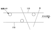
ここで、爆発物の分子(以下「爆薬分子」という)は、吸着しやすい性質をもつ。したがって、図6に示されるように、ガス中に爆薬分子が含まれていた場合には、光ファイバ11の中空部の壁面110に吸着することとなる。そして、このような光ファイバ11内を光源12からの光が伝搬することにより、爆薬分子に応じた波長の光が吸収され、光強度が減少する。爆薬分子の情報が反映された光は、爆発物検知部13により検出される。爆発物検知部13は、検出した光を分光することにより、吸収スペクトルを生成し、吸収波長を解析して爆発物の検知を行なう。
Here, explosive molecules (hereinafter referred to as “explosive molecules”) are easily adsorbed. Therefore, as shown in FIG. 6, when explosive molecules are included in the gas, they are adsorbed on the
図6に吸収スペクトルの一例を示す。図6において、横軸は波長λ、縦軸は透過率を示している。図6に示されるように、ガス中に爆薬分子が含まれていれば、爆発物の種類に相当する波長において光吸収が生ずるため、爆発物検知部13は、透過率の変化点を検出することにより爆発物の存在を検知することができる。
例えば、爆発物検知部13は、吸収波長と爆発分子とを対応付けて予め保有しており、吸収スペクトルにおいて光量が減少している波長を特定することにより、爆薬分子を特定する。爆発物検知部13は、爆発物が検知された場合には、発信機に対して検知信号を出力することにより、異常信号を発信させる。
FIG. 6 shows an example of an absorption spectrum. In FIG. 6, the horizontal axis indicates the wavelength λ and the vertical axis indicates the transmittance. As shown in FIG. 6, if explosive molecules are included in the gas, light absorption occurs at a wavelength corresponding to the type of explosive, so the
For example, the
以上、説明してきたように、本実施形態に係る爆発物検知装置10によれば、簡単な構成原理で爆発物を検知することが可能となる。更に、光ファイバ11を用いるので、小型化を図ることが可能となる。また、光ファイバ11を設置箇所に応じて変形させることにより、設置位置の自由度を高めることが可能となる。
なお、上記爆発物検知装置をエアコンに取り付けた場合には、エアコンの暖気運転の際に、光ファイバ11内に残存している分子を焼却し排出することとしてもよい。これにより、次回検出時の精度を向上させることができる。
As described above, according to the
When the explosive detection device is attached to an air conditioner, the molecules remaining in the
また、上記実施形態では、中空部にガスを流入させ、光ファイバ内を光が伝搬することとしたが、ガスの流通路、光の伝搬路については上記例に限定されない。例えば、光とガスとが同じ流路を流通、伝搬することとしてもよい。要は、ガスに含まれる爆薬分子による光吸収が発生し、この爆薬分子の情報が反映された光を検出して分析するような構成とされていればよい。 In the above embodiment, gas is introduced into the hollow portion and light propagates through the optical fiber. However, the gas flow path and the light propagation path are not limited to the above example. For example, light and gas may be circulated and propagated through the same flow path. In short, light absorption by explosive molecules contained in gas may be generated, and light reflecting the information of explosive molecules may be detected and analyzed.
なお、上記実施形態においては、車内の空気を吸着液に取り込み、この吸着液をガス化したものを光ファイバ11の中空部に流入することとしたが、これに代えて、車内の空気をそのまま光ファイバ11の中空部に流入させることとしてもよい。これにより、更なる小型化を図ることが可能となる。
In the above embodiment, the air in the vehicle is taken into the adsorbing liquid, and the gasified adsorbing liquid flows into the hollow portion of the
なお、上述した爆発物検知装置10は一例であり、例えば、ガスクロマトグラフの質量分析による測定原理を用いたマイクロセンサ、あるいはイオンモビリティスペクトル法に基づくIMS(Ion Mobility Spectrometer)を使用したものを車両1に搭載することとしてもよい。
The
1…車両、2…中継装置、3…管理装置、4…通信網、10…爆発物検知装置、11…光ファイバ、12…光源、13…爆発物検知部、14…吸着器、15…気化器、16…吸収液補充器 DESCRIPTION OF SYMBOLS 1 ... Vehicle, 2 ... Relay apparatus, 3 ... Management apparatus, 4 ... Communication network, 10 ... Explosive substance detection apparatus, 11 ... Optical fiber, 12 ... Light source, 13 ... Explosive substance detection part, 14 ... Adsorber, 15 ... Vaporization , 16 ... Absorbent replenisher
Claims (6)
車両に設置される爆発物検知装置と、
車両に設けられ、該爆発物検知装置により爆発物が検知された場合に、当該車両を特定するための車両認識情報を含む異常信号を所定の期間に渡って発信する発信機と、
道路に設置され、前記発信機から前記異常信号を受信した場合に、該異常信号に含まれる前記車両認識情報を管理装置に送信する複数の中継装置と
を備え、前記異常信号を受信した前記中継装置の位置情報の軌跡をたどることで、爆発物を搭載した前記車両を追尾可能とした不審車両検知システム。 A suspicious vehicle detection system for tracking a suspicious vehicle carrying explosives,
An explosive detection device installed in the vehicle;
A transmitter that is provided in a vehicle and transmits an abnormal signal including vehicle recognition information for identifying the vehicle over a predetermined period when an explosive is detected by the explosive detection device;
A plurality of relay devices installed on a road and transmitting the vehicle recognition information included in the abnormal signal to a management device when the abnormal signal is received from the transmitter, and the relay that has received the abnormal signal A suspicious vehicle detection system capable of tracking the vehicle on which explosives are mounted by following a trajectory of position information of the device .
光源と、
中空構造をなし、中空部に気体が流通するとともに、前記光源から射出された光が伝搬する光ファイバと、
気体が流通する前記光ファイバ内を伝搬した光を検出し、該光の波長とその光量との関係に基づいて前記気体中の爆発物を検知する爆発物検知手段と
を備える請求項1から請求項4のいずれかに記載の不審車両検知システム。 The explosive detection device is:
A light source;
An optical fiber that has a hollow structure, allows gas emitted through the hollow portion and light emitted from the light source to propagate,
An explosive detection means for detecting light propagating through the optical fiber through which gas flows and detecting explosives in the gas based on the relationship between the wavelength of the light and the amount of the light. Item 5. The suspicious vehicle detection system according to any one of Items 4 to 5.
Priority Applications (1)
| Application Number | Priority Date | Filing Date | Title |
|---|---|---|---|
| JP2007092516A JP5111921B2 (en) | 2007-03-30 | 2007-03-30 | Suspicious vehicle detection system |
Applications Claiming Priority (1)
| Application Number | Priority Date | Filing Date | Title |
|---|---|---|---|
| JP2007092516A JP5111921B2 (en) | 2007-03-30 | 2007-03-30 | Suspicious vehicle detection system |
Publications (2)
| Publication Number | Publication Date |
|---|---|
| JP2008249558A JP2008249558A (en) | 2008-10-16 |
| JP5111921B2 true JP5111921B2 (en) | 2013-01-09 |
Family
ID=39974675
Family Applications (1)
| Application Number | Title | Priority Date | Filing Date |
|---|---|---|---|
| JP2007092516A Expired - Fee Related JP5111921B2 (en) | 2007-03-30 | 2007-03-30 | Suspicious vehicle detection system |
Country Status (1)
| Country | Link |
|---|---|
| JP (1) | JP5111921B2 (en) |
Families Citing this family (2)
| Publication number | Priority date | Publication date | Assignee | Title |
|---|---|---|---|---|
| JP2014529735A (en) * | 2011-09-20 | 2014-11-13 | ハリバートンエナジー サヴィシーズ インコーポレイテッド | Systems and tools for detecting prohibited or dangerous substances. |
| KR101372832B1 (en) | 2013-12-18 | 2014-03-11 | 주식회사 디앤에스테크놀로지 | Movable detecting system and method for underbody of vehicle |
Family Cites Families (7)
| Publication number | Priority date | Publication date | Assignee | Title |
|---|---|---|---|---|
| JPH01311247A (en) * | 1988-06-08 | 1989-12-15 | Toshiba Corp | Device for capturing and thickening gaseous component |
| JPH03126342U (en) * | 1990-04-03 | 1991-12-19 | ||
| JPH0950586A (en) * | 1995-05-29 | 1997-02-18 | Shinko Seisakusho:Kk | Crisis management system in passenger mass transport vehicle |
| US6870476B2 (en) * | 2003-04-07 | 2005-03-22 | Bulldog Technologies Inc. | Continuous feedback container security system |
| US20050063869A1 (en) * | 2003-09-24 | 2005-03-24 | Stephane Follonier | Device, system and method of detecting targets in a fluid sample |
| JP2005227965A (en) * | 2004-02-12 | 2005-08-25 | Fujitsu Ten Ltd | Vehicle monitoring device and portable terminal |
| JP2006053645A (en) * | 2004-08-10 | 2006-02-23 | Nec Saitama Ltd | Vehicle monitoring device, vehicle monitoring system, vehicle monitoring method, and electronic device |
-
2007
- 2007-03-30 JP JP2007092516A patent/JP5111921B2/en not_active Expired - Fee Related
Also Published As
| Publication number | Publication date |
|---|---|
| JP2008249558A (en) | 2008-10-16 |
Similar Documents
| Publication | Publication Date | Title |
|---|---|---|
| JP4550802B2 (en) | Obstacle substance detection method and obstacle substance detection system | |
| US8086266B2 (en) | Cell phone based MEMS fourier transform infrared (FTIR) gas sensors | |
| US7544943B2 (en) | Method and system for remote exhaust emission measurement | |
| Kirchstetter et al. | Measurement of nitrous acid in motor vehicle exhaust | |
| US9322802B2 (en) | Apparatus for detecting chemical substances | |
| US9040905B2 (en) | Analysis device and analysis method | |
| EP3572795A1 (en) | Carbon isotope analysis device and carbon isotope analysis method | |
| Mamakos et al. | Assessment of portable emission measurement systems (PEMS) for heavy-duty diesel engines with respect to particulate matter | |
| KR20060008967A (en) | Accident detection system | |
| CN102770749A (en) | Gas concentration monitor | |
| US20210383666A1 (en) | Fire detection system and fire detection method | |
| US20050092067A1 (en) | Detector with condenser | |
| CN103827652A (en) | System and method for quantifying the presence of components in vehicle exhaust | |
| DE50202632D1 (en) | OUTSIDE FIRE DETECTION DEVICE | |
| EP2338044A2 (en) | Method and apparatus for sensing the nature of a gaseous composition, particularly vehicular emissions | |
| WO2007082426A1 (en) | Method and system for remote exhaust emission measurement | |
| WO2006119424A2 (en) | Method and apparatus for detecting the presence of elemental mercury in a gas sample | |
| US7835873B2 (en) | Method and system for monitoring changes in a sample for a process or an environment | |
| Wang et al. | A demonstration of broadband cavity-enhanced absorption spectroscopy at deep-ultraviolet wavelengths: Application to sensitive real-time detection of the aromatic pollutants benzene, toluene, and xylene | |
| CN108132228A (en) | A kind of vehicle exhaust telemetering equipment | |
| JP2008249558A (en) | Explosive detector and suspicious vehicle detection system | |
| US11959859B2 (en) | Multi-gas detection system and method | |
| US20250187557A1 (en) | Emergency door release device | |
| JP3411783B2 (en) | Gas leak detection device | |
| CN207964620U (en) | A kind of automobile interior exterior portion gaseous environment monitoring purifying control system based on mixed laser gas detection |
Legal Events
| Date | Code | Title | Description |
|---|---|---|---|
| A621 | Written request for application examination |
Free format text: JAPANESE INTERMEDIATE CODE: A621 Effective date: 20090716 |
|
| A977 | Report on retrieval |
Free format text: JAPANESE INTERMEDIATE CODE: A971007 Effective date: 20110517 |
|
| A131 | Notification of reasons for refusal |
Free format text: JAPANESE INTERMEDIATE CODE: A131 Effective date: 20110524 |
|
| A521 | Written amendment |
Free format text: JAPANESE INTERMEDIATE CODE: A523 Effective date: 20110725 |
|
| A131 | Notification of reasons for refusal |
Free format text: JAPANESE INTERMEDIATE CODE: A131 Effective date: 20111101 |
|
| A521 | Written amendment |
Free format text: JAPANESE INTERMEDIATE CODE: A523 Effective date: 20120104 |
|
| A02 | Decision of refusal |
Free format text: JAPANESE INTERMEDIATE CODE: A02 Effective date: 20120515 |
|
| A521 | Written amendment |
Free format text: JAPANESE INTERMEDIATE CODE: A523 Effective date: 20120815 |
|
| A911 | Transfer of reconsideration by examiner before appeal (zenchi) |
Free format text: JAPANESE INTERMEDIATE CODE: A911 Effective date: 20120822 |
|
| TRDD | Decision of grant or rejection written | ||
| A01 | Written decision to grant a patent or to grant a registration (utility model) |
Free format text: JAPANESE INTERMEDIATE CODE: A01 Effective date: 20120918 |
|
| A01 | Written decision to grant a patent or to grant a registration (utility model) |
Free format text: JAPANESE INTERMEDIATE CODE: A01 |
|
| A61 | First payment of annual fees (during grant procedure) |
Free format text: JAPANESE INTERMEDIATE CODE: A61 Effective date: 20121010 |
|
| FPAY | Renewal fee payment (event date is renewal date of database) |
Free format text: PAYMENT UNTIL: 20151019 Year of fee payment: 3 |
|
| FPAY | Renewal fee payment (event date is renewal date of database) |
Free format text: PAYMENT UNTIL: 20151019 Year of fee payment: 3 |
|
| LAPS | Cancellation because of no payment of annual fees |