JP5113413B2 - Aluminum ingot casting method - Google Patents
Aluminum ingot casting method Download PDFInfo
- Publication number
- JP5113413B2 JP5113413B2 JP2007093665A JP2007093665A JP5113413B2 JP 5113413 B2 JP5113413 B2 JP 5113413B2 JP 2007093665 A JP2007093665 A JP 2007093665A JP 2007093665 A JP2007093665 A JP 2007093665A JP 5113413 B2 JP5113413 B2 JP 5113413B2
- Authority
- JP
- Japan
- Prior art keywords
- casting
- mold
- aluminum
- supplied
- aluminum ingot
- Prior art date
- Legal status (The legal status is an assumption and is not a legal conclusion. Google has not performed a legal analysis and makes no representation as to the accuracy of the status listed.)
- Expired - Fee Related
Links
Images


Landscapes
- Continuous Casting (AREA)
Description
本発明は、例えば、反射板、スパッタターゲット材、電解コンデンサーの電極箔などの圧延素材として有用なアルミニウム鋳塊を半連続して鋳造する、アルミニウム鋳塊の鋳造方法および該鋳造方法に用いる鋳造装置に関する。 The present invention relates to a casting method for an aluminum ingot, and a casting apparatus used for the casting method, in which an aluminum ingot useful as a rolling material such as a reflector, a sputtering target material, and an electrode foil of an electrolytic capacitor is semi-continuously cast. About.
従来から、高純度アルミニウムの板や箔は、反射板、スパッタターゲット材、電解コンデンサーの電極箔などに使用されている。これら用途に用いる板や箔には、表面処理性、結晶方位、再結晶粒径などが均一であることが求められる。このような板や箔の特性は、鋳塊材料の鋳造工程に引き続き行われる均質化処理工程や圧延加工工程で主に制御されるが、素材として用いる鋳塊の均一性にも影響される。 Conventionally, high-purity aluminum plates and foils have been used for reflectors, sputter target materials, electrolytic capacitor electrode foils, and the like. Plates and foils used for these applications are required to have uniform surface treatability, crystal orientation, recrystallized grain size, and the like. The characteristics of such plates and foils are mainly controlled in a homogenization process and a rolling process performed subsequent to the casting process of the ingot material, but are also affected by the uniformity of the ingot used as a raw material.
素材として用いられる高純度アルミニウム鋳塊は、種々の鋳造方法により製造されるが、中でも水冷却縦型半連続鋳造鋳型を用いた鋳造方法が最も一般的である。詳しくは、上下を開放した四角柱形を呈した中空部を有する筒状の鋳型に、上部からアルミニウム溶湯を供給し、鋳型周囲の筒内に供給した冷却水により鋳壁を通して1次冷却するとともに、前記冷却水を鋳型の下端から斜め下向きに注加することにより2次冷却することでアルミニウム溶湯を凝固させて、連続的に下部から引き抜くことにより、鋳塊を一定の長さに鋳造する、いわゆる半連続鋳造方法である。この場合、通常、熱伝導性の観点から、銅、アルミニウム等の金属からなる鋳型が用いられている。 The high-purity aluminum ingot used as a raw material is manufactured by various casting methods, but the casting method using a water-cooled vertical semi-continuous casting mold is the most common. More specifically, molten aluminum is supplied from the top to a cylindrical mold having a hollow portion having a quadrangular prism shape that is open at the top and bottom, and is primarily cooled through the casting wall with cooling water supplied into the cylinder around the mold. , By casting the cooling water obliquely downward from the lower end of the mold, the molten aluminum is solidified by secondary cooling, and continuously drawn out from the lower part, thereby casting the ingot to a certain length. This is a so-called semi-continuous casting method. In this case, a mold made of a metal such as copper or aluminum is usually used from the viewpoint of thermal conductivity.
しかしながら、上述した従来公知の水冷却縦型半連続鋳造鋳型を用いると、溶湯の温度は1次冷却から徐々に下がり、2次冷却で強制的に冷却されて凝固するまでに、ある程度の時間がかかることになる。換言すれば、溶湯の冷却は緩やかに進行することになり、その結果、2次冷却で直接水冷される鋳肌付近のマクロ組織やミクロ組織は細かくなり、鋳塊中心部分のマクロ組織やミクロ組織は粗くなるという不均一性を招く傾向があった。このような不均一性は、得られたアルミニウム鋳塊を板材や箔材として用いる場合に、板や箔の幅方向や厚さ方向の結晶方位や再結晶粒径、表面処理性などに悪影響を及ぼし、製品としての歩留まりを低下させる。
また、上述した従来公知の水冷却縦型半連続鋳造鋳型を用いた場合、鋳型を構成する金属とアルミニウム溶湯との滑り性が不充分であるという問題もあった。アルミニウム溶湯の滑りが悪いと、鋳造中に凝固した部分が降下しないといった問題を生じる。
However, when the above-described conventionally known water-cooled vertical semi-continuous casting mold is used, the temperature of the molten metal gradually decreases from the primary cooling, and a certain amount of time is required until it is forcibly cooled and solidified by the secondary cooling. It will take. In other words, the cooling of the molten metal proceeds slowly, and as a result, the macrostructure and microstructure near the casting surface that are directly water-cooled by secondary cooling become finer, and the macrostructure and microstructure of the ingot center portion. Tended to lead to inhomogeneities of roughening. Such non-uniformity adversely affects the crystal orientation in the width direction and thickness direction of the plate or foil, the recrystallized grain size, surface treatment properties, etc. when the obtained aluminum ingot is used as a plate material or foil material. And reduce the product yield.
In addition, when the above-described conventionally known water-cooled vertical semi-continuous casting mold is used, there is a problem that the sliding property between the metal constituting the mold and the molten aluminum is insufficient. If the molten aluminum does not slide smoothly, there is a problem that the solidified part does not fall during casting.
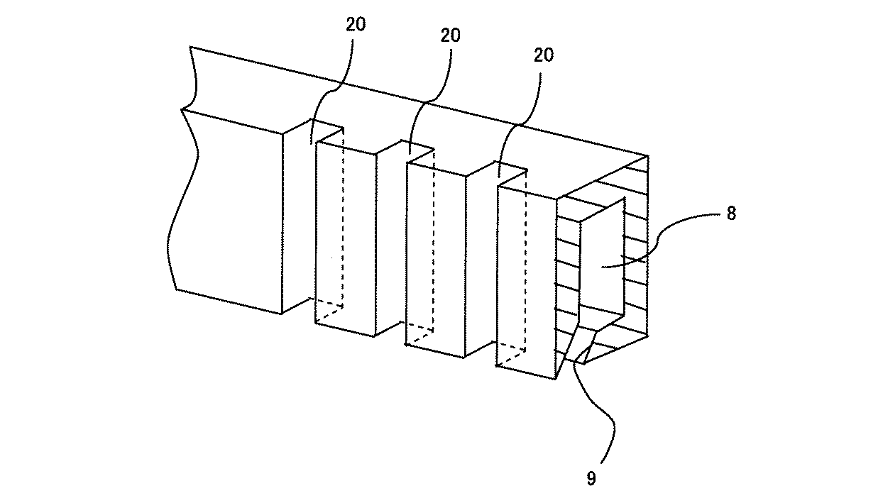
そこで、これまで、鋳型表面を粗面化したり(特許文献1参照)、もしくは図4に示すように鋳造方向(溶湯の進行方向)に複数の溝20を設けたりすることにより、アルミニウム溶湯と鋳型との接触面を少なくし、それによって、鋳型に断熱性を付与して1次冷却における溶湯の温度低下を抑制するとともに、アルミニウム溶湯の滑り性をも改善するようにした金属製鋳型が提案されていた。
しかしながら、従来の金属製鋳型では、アルミニウム溶湯の滑り性はかなり改善されるものの、断熱性については、未だ得られる鋳塊のマクロ組織やミクロ組織の均一性が満足しうるレベルに達するまでには至らないのが現状であった。 However, with the conventional metal mold, the slipperiness of the molten aluminum is considerably improved, but the thermal insulation performance is still not satisfactory until the uniformity of the macrostructure and microstructure of the resulting ingot is reached. The situation was not reached.
そこで、本発明の目的は、表面付近から内部にかけてのマクロ組織やミクロ組織の均一性に優れたアルミニウム鋳塊を半連続して鋳造することができる、アルミニウム鋳塊の鋳造方法および該鋳造方法に用いる鋳造装置を提供することである。 Accordingly, an object of the present invention is to provide a casting method for an aluminum ingot and the casting method capable of semi-continuously casting an aluminum ingot excellent in uniformity of a macro structure and a microstructure from the vicinity of the surface to the inside. It is to provide a casting apparatus to be used.
本発明者らは、上記課題を解決するべく鋭意研究を重ねた結果、水冷却縦型半連続鋳造鋳型を用いてアルミニウム鋳塊を半連続鋳造するにあたり、アルミニウム溶湯と接触する鋳型内面の一部を黒鉛製の板で代替した鋳型を用いるとともに、鋳型に供給するアルミニウム溶湯の温度(鋳造温度)を760℃以上と従来よりも高く設定し、かつ冷却水の水量を25L/kg−Al以上と従来よりも多く使用することにより、表面付近から内部にかけてのマクロ組織やミクロ組織が均一な鋳塊を半連続鋳造できることを見出した。 As a result of intensive research to solve the above-mentioned problems, the present inventors have found that a part of the inner surface of the mold that comes into contact with the molten aluminum in semi-continuous casting of an aluminum ingot using a water-cooled vertical semi-continuous casting mold. Is used instead of a graphite plate, the temperature of the molten aluminum supplied to the mold (casting temperature) is set to 760 ° C. or higher, and the amount of cooling water is 25 L / kg-Al or more. It has been found that by using more than before, an ingot having a uniform macrostructure and microstructure from the surface to the inside can be semi-continuously cast.
すなわち、アルミニウム溶湯と接触する鋳型内面の一部を黒鉛製の板で代替した鋳型を用いることにより、アルミニウム溶湯の滑り性が確保されると同時に、より確実な断熱性を発現させて溶湯が鋳型に接する領域において溶湯の熱が過剰に奪われることを回避することができる。このような鋳型において高温の溶湯を供給すると、溶湯は、高温を維持したままで鋳型との接触領域を通過し、鋳型の下端から斜め下向きに注加される冷却水によって高温状態から一気に急冷される。このような急冷により凝固させた場合、鋳塊の内部の冷却速度と表面付近の冷却速度との差を小さく抑えることができ、その結果、マクロ組織やミクロ組織の均一化が図れるのである。本発明は、これらの知見により完成されたものである。 That is, by using a mold in which a part of the inner surface of the mold that is in contact with the molten aluminum is replaced with a graphite plate, the molten aluminum is ensured to be slidable, and at the same time, a more reliable heat insulating property is exhibited and the molten metal is cast. It is possible to avoid excessive deprivation of the heat of the molten metal in the region in contact with. When a high-temperature molten metal is supplied to such a mold, the molten metal is rapidly cooled from a high-temperature state at once by cooling water that is poured obliquely downward from the lower end of the mold while maintaining the high temperature. The When solidified by such rapid cooling, the difference between the cooling rate inside the ingot and the cooling rate near the surface can be kept small, and as a result, the macrostructure and the microstructure can be made uniform. The present invention has been completed based on these findings.
本発明は以下の構成からなる。
(1)上下を開放した四角柱形を呈した中空部を有する筒状の水冷却縦型半連続鋳造鋳型の前記中空部に、その上部からアルミニウム溶湯を供給し、冷却水によって凝固させて、連続的に下部から引き抜くことにより、アルミニウム鋳塊を半連続的に鋳造する方法において、アルミニウム溶湯が供給される前記中空部に接する側面の鋳造方向の1/2以上が黒鉛製の板で構成されている鋳型(ただし、アルミニウム溶湯が供給される前記中空部に接する側面の全体が黒鉛製の板で構成されている鋳型を除く。)を用いるとともに、鋳型に供給するアルミニウム溶湯の温度を760℃以上とし、かつ、冷却水を鋳型下部のスリットから25L/kg−Al以上で放出する、ことを特徴とするアルミニウム鋳塊の鋳造方法。
(2)前記黒鉛製の板は、四角柱形を呈した中空部の角部には配されていない、前記(1)記載のアルミニウム鋳塊の鋳造方法。
(3)鋳造速度は55mm/分以下とする、前記(1)または(2)記載のアルミニウム鋳塊の鋳造方法。
(4)前記(1)〜(3)のいずれかに記載のアルミニウム鋳塊の鋳造方法に用いる鋳造装置であって、上下を開放した四角柱形を呈した中空部を有する筒状の水冷却縦型半連続鋳造鋳型と、該鋳型の中心軸付近に上方から垂下するスパウトと、該スパウトの下端付近に水平に配設された分流板と、前記鋳型の下方において昇降自在に位置するボトムブロックとを備え、前記鋳型のうちアルミニウム溶湯が供給される前記中空部に接する側面の鋳造方向の1/2以上(ただし、アルミニウム溶湯が供給される前記中空部に接する側面の全体を除く。)が黒鉛製の板で構成されている、ことを特徴とするアルミニウム鋳塊の鋳造装置。
(5)前記黒鉛製の板は、四角柱形を呈した中空部の角部には配されていない、前記(4)記載のアルミニウム鋳塊の鋳造装置。
(6)前記黒鉛製の板は、着脱可能に構成されている、前記(4)または(5)記載のアルミニウム鋳塊の鋳造装置。
なお、本明細書におけるアルミニウムには、純アルミニウムはもとより、各種のアルミニウム合金も含まれる。
The present invention has the following configuration.
(1) Supplying molten aluminum from the upper part to the hollow part of a cylindrical water-cooled vertical semi-continuous casting mold having a hollow part that has a rectangular column shape with an open top and bottom, solidified with cooling water, In a method of semi-continuously casting an aluminum ingot by continuously pulling out from the lower part, at least half of the casting direction of the side surface in contact with the hollow portion to which the molten aluminum is supplied is composed of a graphite plate. And the temperature of the molten aluminum supplied to the mold is 760 ° C. ( excluding the mold whose entire side surface contacting the hollow portion to which the molten aluminum is supplied is made of a graphite plate). A casting method for an aluminum ingot, characterized in that the cooling water is discharged at a rate of 25 L / kg-Al or more from the slit at the bottom of the mold.
(2) The method for casting an aluminum ingot according to (1), wherein the graphite plate is not disposed at a corner of a hollow portion having a quadrangular prism shape.
(3) The method for casting an aluminum ingot according to (1) or (2), wherein the casting speed is 55 mm / min or less.
(4) A casting apparatus for use in the method for casting an aluminum ingot according to any one of (1) to (3), wherein the cylindrical water cooling has a hollow portion having a quadrangular prism shape with the top and bottom open. A vertical semi-continuous casting mold, a spout hanging from above near the center axis of the mold, a flow dividing plate horizontally disposed near the lower end of the spout, and a bottom block positioned so as to be movable up and down below the mold More than half of the casting direction of the side surface in contact with the hollow portion to which the molten aluminum is supplied (excluding the entire side surface in contact with the hollow portion to which the molten aluminum is supplied). An apparatus for casting an aluminum ingot, characterized by comprising a plate made of graphite.
(5) The aluminum ingot casting apparatus according to (4), wherein the graphite plate is not disposed in a corner portion of a hollow portion having a quadrangular prism shape.
(6) The apparatus for casting an aluminum ingot according to (4) or (5), wherein the graphite plate is configured to be detachable.
In addition, the aluminum in this specification includes various aluminum alloys as well as pure aluminum.
本発明によれば、表面付近から内部にかけてのマクロ組織やミクロ組織の均一性に優れたアルミニウム鋳塊を半連続鋳造することができる、という効果が得られる。さらに、得られるアルミニウム鋳塊のマクロ組織が均一であると、均質化処理において均質な再結晶特性が得られる、という利点もある。また、得られるアルミニウム鋳塊のミクロ組織が均一であると、均質化処理の際に溶質元素が均一に固溶しやすく、均質化処理温度を下げたり、処理時間を短縮したりすることが可能になり、エネルギーコスト等の点でも有利になる。 According to the present invention, an effect that semi-continuous casting of an aluminum ingot having excellent macro structure and micro structure uniformity from near the surface to the inside can be obtained. Furthermore, if the macrostructure of the resulting aluminum ingot is uniform, there is an advantage that uniform recrystallization characteristics can be obtained in the homogenization process. In addition, if the microstructure of the resulting aluminum ingot is uniform, the solute elements are likely to be uniformly solid-dissolved during the homogenization process, and the homogenization process temperature can be lowered and the processing time can be shortened. This is also advantageous in terms of energy costs.
以下、図面を用いて、本発明の鋳造装置の一実施形態について説明する。
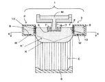
図1は、本発明のアルミニウム鋳塊の鋳造方法に好ましく用いることができる本発明の鋳造装置の一実施形態を垂直断面にて示す概略図であり、図2は、図1に示す装置における鋳型3を部分的に拡大して示す垂直断面図であり、図3は、図1に示す装置における鋳型3をX−X断面で切断したときの断面図である。
Hereinafter, an embodiment of a casting apparatus of the present invention will be described with reference to the drawings.
FIG. 1 is a schematic view showing a vertical section of an embodiment of a casting apparatus of the present invention that can be preferably used in the method for casting an aluminum ingot of the present invention, and FIG. 2 is a mold in the apparatus shown in FIG. 3 is a partially enlarged vertical sectional view of FIG. 3, and FIG. 3 is a sectional view of the
図1に示すように、装置1は、上下を開放した四角柱形を呈した中空部2を有する筒状の水冷却縦型鋳型3と、この鋳型3の中心軸付近に上方から垂下するスパウト4と、スパウト4の下端付近に水平に配設された分流板5と、鋳型3の下方において昇降自在に位置するボトムブロック6とを備えており、さらに、スパウト4の下方の外側には、供給されたアルミニウム溶湯M上に浮上する矩形のフロート7が配される。なお、中空部2は、図3に示すように平面視で長方形を呈し、通常、短辺300〜600mm、長辺1000〜2000mm程度のサイズを有する。
As shown in FIG. 1, the apparatus 1 includes a cylindrical water-cooled
鋳型3は、中空部2の外側に断面角形の冷却水用中空部8を有する形状になっている。そして、その下端の中空部2側には、斜め下向きにスリット9が形成されており、中空部8に供給した冷却水Wを中空部2より下方のアルミニウム溶湯Mに対して斜め下向きに注加することができるようになっている。
The
鋳型3は、中空部2に接する側面、すなわちアルミニウム溶湯Mとの接触面の一部が、黒鉛製の板10で構成されている。黒鉛製の板10は、例えば、図2に示すように、鋳型3の中空部2に接する側面からその上部にかけて黒鉛製の板10を装着するスペースを設けておき、そのスペースに黒鉛製の板10を嵌め込み、その上部に嵌め込んだ蓋部材11をボルト12で固定することにより、着脱可能に構成される。このように、黒鉛製の板10が着脱可能であれば、凝固したアルミニウム溶湯Mとの接触等により黒鉛製の板10が傷付き、消耗・劣化した場合にも、取替え等のメンテナンスが容易になるという利点が得られる。
The
黒鉛製の板10は、好ましくは、図3に示すように、四角柱形を呈した中空部2の角部2’には配されていない。これにより、中空部2に供給されたアルミニウム溶湯Mは、鋳型3に接触している状態において、角部のみが断熱効果を受けることがなく若干凝固が進行することになるので、ボトムブロック6により下方に引き抜く際に、アルミニウム溶湯Mが鋳型3のコーナー部から漏れ出すことなく、比較的安定した形状を保持することができ、その結果、所望の鋳造速度での引き抜きが可能になる。なお、この場合、得られる鋳塊Cの角部は、他の部分と比較して、マクロ組織およびミクロ組織が均一にならない傾向があるが、板材や箔材とする際に面削したり、端部として除去したりすることにより、その悪影響は排除できる。
The
鋳型3の構成部材のうち黒鉛製の板10以外の部分(蓋部材11を含む)の素材は、特に制限はなく、一般的には銅やアルミニウム等の金属で構成されるが、軽量性や耐汚染性に優れる点でアルミニウム製であることが好ましい。
The material of the part other than the graphite plate 10 (including the lid member 11) among the constituent members of the
次に、本発明のアルミニウム鋳塊の鋳造方法の一実施形態について説明する。該実施形態においては、上述した図1に示す装置1を用いて、中空部2に、その上部からアルミニウム溶湯Mを供給し、冷却水Wによって凝固させて、連続的に下部から引き抜くことにより、アルミニウム鋳塊を半連続的に鋳造する。
Next, an embodiment of a casting method for an aluminum ingot according to the present invention will be described. In this embodiment, by using the apparatus 1 shown in FIG. 1 described above, the molten aluminum M is supplied to the
アルミニウム溶湯Mを供給するに際しては、予め、鋳型3の中空部2の下部にボトムブロック6を配置しておく。この状態で、予め不純物を除去して精製したアルミニウムまたは必要な元素を適宜配合したアルミニウム合金の溶湯Mをスパウト4から注下し、分流板5に衝突させて、溶湯Mを中空部2内に放射状に供給する。このとき、フロート7を配しておくことで、一定量の溶湯Mが中空部2内に均一に充填される。ボトムブロック6は、供給したアルミニウム溶湯Mが中空部2内に充填されるとともに、下方に降下させる。
When supplying the molten aluminum M, the bottom block 6 is arranged in advance under the
鋳型3に供給するアルミニウム溶湯Mの温度(鋳造温度)は、760℃以上とすることが重要であり、好ましくは780℃以上であるのがよい。鋳造温度が760℃未満であると、溶湯Mが冷却水の注加により冷却される際の温度勾配が小さくなり(換言すれば、急冷されなくなり)、マクロ組織やミクロ組織の均一化が不充分となる。
The temperature (casting temperature) of the molten aluminum M supplied to the
他方、鋳型3の冷却水用中空部8には、冷却水供給孔(図示せず)から所定の流量で連続して冷却水Wを供給し、鋳型3の下端のスリット9から斜め下向きに放出させる。
鋳型3下部のスリット9から放出させる冷却水Wの量は、25L/kg−Al以上(中空部2内に供給されたアルミニウム溶湯M1kg当たり25L以上)とする。好ましくは、30L/kg−Al以上とするのがよい。冷却水Wの量が25L/kg−Al未満であると、溶湯Mが冷却される際の温度勾配が小さくなり(換言すれば、急冷されなくなり)、マクロ組織やミクロ組織の均一化が不充分となる。
On the other hand, the cooling water
The amount of the cooling water W to be discharged from the
このように、鋳造温度および冷却水Wの放出量を上記範囲とすることによって、中空部2内に順次供給された溶湯Mは、殆ど熱を奪われることなく(ただし、実際には、加温や保温されない環境で自然に起こる僅かな放熱により、溶湯Mの形状を保持するための数ミリメートル程度の凝固層が表面にのみ形成されることになる)、鋳型3との接触領域、すなわち中空部2を通過した後、鋳型3の下端のスリット9から斜め下向きに注加される冷却水Wによって供給時の温度から一気に急冷され、その外側面から内部にかけて急速に凝固する。このように凝固した場合、図1に示す凝固界面Kの下方に鋳塊Cが順次形成される。
As described above, by setting the casting temperature and the discharge amount of the cooling water W within the above ranges, the molten metal M sequentially supplied into the
例えば、上記鋳型3に変えて、従来から汎用されている図4に示すような溝付きの金属製鋳型を用いた場合には、溶湯Mは鋳型との接触領域から徐々に冷却され始めるので、溶湯Mが鋳塊Cに変化する凝固界面は、図1に破線K’で示すように、鋳型との接触領域から徐々に低くなり、次いで冷却水Wにより冷却されて中心部寄りに延び、中心部付近が最も低く尖った形状となる。また、上記鋳型3を用いた場合であっても、鋳造温度および冷却水Wの放出量を上記範囲外とした場合などには、凝固界面の始点は、溶湯Mに冷却水Wが直接接触する表面(鋳肌)付近から低下することになるが、冷却時の温度勾配は本発明の鋳造方法による場合よりも小さくなるので、凝固界面の形状はやはり中心部付近が最も低く尖った形状となる。これに対し、本発明の鋳造方法によれば、凝固界面Kは、図1に示すように、鋳型3の下端の冷却水Wが注加される部分から徐々に低くなり、中心部付近にかけてほぼ平らな線を描くものとなる。これにより、表面付近から内部にかけてのマクロ組織やミクロ組織の均一性に優れたアルミニウム鋳塊Cが得られるのである。
For example, instead of the above-mentioned
形成された鋳塊Cをボトムブロック6により連続的に下部から引き抜く際には、ボトムブロック6の降下速度、すなわち鋳造速度を55mm/分以下とするのが好ましく、より好ましくは40〜50mm/分とするのがよい。鋳造速度が前記範囲よりも速いと、マクロ組織やミクロ組織の均一性が低下したり、鋳造中に溶湯Mが漏れたりするおそれがある。一方、鋳造速度があまりに遅すぎると、生産効率が低下するので好ましくない。 When the formed ingot C is continuously pulled out from the lower portion by the bottom block 6, the lowering speed of the bottom block 6, that is, the casting speed is preferably 55 mm / min or less, more preferably 40 to 50 mm / min. It is good to do. If the casting speed is faster than the above range, the uniformity of the macro structure and the microstructure may be reduced, or the molten metal M may leak during casting. On the other hand, if the casting speed is too slow, production efficiency is lowered, which is not preferable.
以下、実施例によって本発明を詳細に説明するが、本発明は以下の実施例に限定されるものではない。
(実施例1)
アルミニウム溶解炉にて三層電解精製した高純度アルミニウム2000kgを溶融し、組成を、Si:10ppm、Fe:7ppm、Cu:33ppmに調整して、アルミニウム溶湯を得た。このアルミニウム溶湯を790℃に保持しつつ、図1〜図3に示すように、一部に黒鉛製の板を備えたアルミニウム製水冷却縦型半連続鋳造鋳型(鋳型3の寸法は、深さ(鋳造方向の長さ):100mm(内、黒鉛製の板:50mm)、中空部2の長辺:1000mm(内、黒鉛製の板:960mm)、中空部2の短辺:400mm(内、黒鉛製の板:360mm))に供給し(鋳造温度790℃)、冷却水を鋳型下部のスリットから30L/kg−Alで放出して凝固させ、50mm/分で下部から引き抜く(鋳造速度50mm/分)ことにより、2000mm長さの鋳塊材を得た。
EXAMPLES Hereinafter, although an Example demonstrates this invention in detail, this invention is not limited to a following example.
Example 1
2000 kg of high-purity aluminum purified in three layers in an aluminum melting furnace was melted, and the composition was adjusted to Si: 10 ppm, Fe: 7 ppm, Cu: 33 ppm to obtain a molten aluminum. While maintaining this molten aluminum at 790 ° C., as shown in FIGS. 1 to 3, an aluminum water-cooled vertical semi-continuous casting mold partially equipped with a graphite plate (the dimension of the
(比較例1)
実施例1で用いた鋳型に代えて、図4に示すように、1.3mm間隔で幅0.8mm、深さ0.5mmの溝を有する細密溝付きアルミニウム製水冷却縦型半連続鋳造鋳型を用い、冷却水を鋳型下部のスリットから20L/kg−Alで放出して凝固させたこと以外は、実施例1と同様にして、2000mm長さの鋳塊材を得た。
(Comparative Example 1)
Instead of the mold used in Example 1, as shown in FIG. 4, an aluminum water-cooled vertical semi-continuous casting mold with fine grooves having grooves of 0.8 mm in width and 0.5 mm in depth at intervals of 1.3 mm Ingot material having a length of 2000 mm was obtained in the same manner as in Example 1 except that cooling water was discharged from the slit at the bottom of the mold at 20 L / kg-Al and solidified.
(比較例2)
実施例1で用いた鋳型に代えて、図4に示すように、5mm間隔で幅2mm、深さ0.5mmの溝を有する粗溝付きアルミニウム製水冷却縦型半連続鋳造鋳型を用い、鋳造温度を740℃とし、冷却水を鋳型下部のスリットから20L/kg−Alで放出して凝固させたこと以外は、実施例1と同様にして、2000mm長さの鋳塊材を得た。
(Comparative Example 2)
Instead of the mold used in Example 1, as shown in FIG. 4, an aluminum water-cooled vertical semi-continuous casting mold with a rough groove having grooves with a width of 2 mm and a depth of 0.5 mm at intervals of 5 mm was used for casting. An ingot material having a length of 2000 mm was obtained in the same manner as in Example 1 except that the temperature was set to 740 ° C. and cooling water was discharged from the slit at the bottom of the mold at 20 L / kg-Al and solidified.
以上の実施例および比較例で得られたアルミニウム鋳塊におけるマクロ組織およびミクロ組織の均一性に関して、以下の方法で評価した。結果は表1に示す。 The uniformity of the macro structure and the microstructure in the aluminum ingot obtained in the above Examples and Comparative Examples was evaluated by the following methods. The results are shown in Table 1.
<マクロ組織結晶粒径>
鋳塊の鋳造方向(凝固方向)に直交する断面で切断してなる試料を、25℃の王水(塩酸:硝酸(重量比)=3:1)に3〜10分間浸漬して、充分にエッチングすることにより、前記断面にマクロ組織が表れるようにした。このマクロ組織を目視にて観察し、鋳肌近傍のマクロ組織結晶粒径と鋳塊内部のマクロ組織結晶粒径を、長さ250mmの直線を横切る結晶粒の個数(X)を計数して下記式に基づき算出した。なお、結晶粒を計数するに際し、比較的細粒である鋳肌近傍では、鋳肌から15mm内部に位置する部分で計数し(換言すると、計数する長さ250mmの直線が全長にわたり鋳肌から15mm内部に位置するように設定する)、その値を代表値とした。他方、粗粒である鋳塊内部では、鋳肌からそれぞれ50mm、100mm、150mm内部に位置する3箇所の部分で計数し(換言すると、計数する長さ250mmの直線が全長にわたり鋳肌からそれぞれ50mm、100mm、150mm内部に位置するように設定する)、それらの平均値を代表値とした。
マクロ組織結晶粒径(mm)=250mm/個数(X)
<Macro-structure crystal grain size>
A sample cut by a cross section orthogonal to the casting direction (solidification direction) of the ingot is immersed in aqua regia (hydrochloric acid: nitric acid (weight ratio) = 3: 1) at 25 ° C. for 3 to 10 minutes, Etching was performed so that a macro structure appeared in the cross section. This macrostructure is visually observed, the macrostructure crystal grain size near the casting surface and the macrostructure crystal grain size inside the ingot are counted by counting the number (X) of crystal grains crossing a straight line having a length of 250 mm. Calculated based on the formula. When counting crystal grains, in the vicinity of the casting surface, which is relatively fine, the counting is performed at a portion located 15 mm from the casting surface (in other words, a straight line with a length of 250 mm is 15 mm from the casting surface over the entire length. The value is set as a representative value. On the other hand, in the ingot, which is a coarse particle, counting is performed at three portions located inside 50 mm, 100 mm, and 150 mm from the casting surface (in other words, a straight line having a length of 250 mm to be counted is 50 mm from the casting surface over the entire length. , 100 mm, and 150 mm), and the average value thereof was used as a representative value.
Macrostructure crystal grain size (mm) = 250 mm / number (X)
<ミクロ組織間隔>
鋳塊の鋳造方向(凝固方向)に平行する断面で切断してなる試料に、エメリー研磨、バフ研磨、電解研磨を順次施した後、50℃の5%NaOH水溶液にて5分間エッチングすることにより、前記断面にミクロ組織が表れるようにした。このミクロ組織には、不純物の濃縮した部分がエッチングで除去されたことで鋳造方向に平行に生じた複数のセルが観察される。このミクロ組織を50倍の金属顕微鏡にて観察し、ミクロ組織においてセルが平行して観察される部分の間隔(ミクロ組織のセル間隔)を計測した。
<Microstructure spacing>
By sequentially emery polishing, buffing, and electrolytic polishing on a sample cut in a cross section parallel to the casting direction (solidification direction) of the ingot, and then etching with a 5% NaOH aqueous solution at 50 ° C. for 5 minutes. The microstructure appeared in the cross section. In this microstructure, a plurality of cells generated in parallel with the casting direction are observed by removing the portion where impurities are concentrated by etching. This microstructure was observed with a 50-fold metal microscope, and the interval between the cells in which the cells were observed in parallel in the microstructure (cell interval of the microstructure) was measured.
1 装置
2 中空部
3 水冷却縦型鋳型
4 スパウト
5 分流板
6 ボトムブロック
7 フロート
8 冷却水用中空部
9 スリット
10 黒鉛製の板
11 蓋部材
12 ボルト
M アルミニウム溶湯
W 冷却水
C アルミニウム鋳塊
DESCRIPTION OF SYMBOLS 1
Claims (6)
アルミニウム溶湯が供給される前記中空部に接する側面の鋳造方向の1/2以上が黒鉛製の板で構成されている鋳型(ただし、アルミニウム溶湯が供給される前記中空部に接する側面の全体が黒鉛製の板で構成されている鋳型を除く。)を用いるとともに、鋳型に供給するアルミニウム溶湯の温度を760℃以上とし、かつ、冷却水を鋳型下部のスリットから25L/kg−Al以上で放出する、ことを特徴とするアルミニウム鋳塊の鋳造方法。 To the hollow part of the cylindrical water-cooled vertical semi-continuous casting mold having a hollow part that has a rectangular column shape that is open at the top and bottom, molten aluminum is supplied from the upper part and solidified by cooling water. In a method of semi-continuously casting an aluminum ingot by pulling out from the lower part,
A mold in which at least half of the casting direction of the side surface in contact with the hollow portion to which the molten aluminum is supplied is made of a graphite plate (however, the entire side surface in contact with the hollow portion to which the molten aluminum is supplied is graphite. excluding mold that consists of manufacturing of the plate.) with use, the temperature of the molten aluminum is supplied to the mold and 760 ° C. or higher, and, emitting at the cooling water from the mold bottom of the slit 25L / kg-Al or The casting method of the aluminum ingot characterized by the above-mentioned.
Priority Applications (1)
| Application Number | Priority Date | Filing Date | Title |
|---|---|---|---|
| JP2007093665A JP5113413B2 (en) | 2007-03-30 | 2007-03-30 | Aluminum ingot casting method |
Applications Claiming Priority (1)
| Application Number | Priority Date | Filing Date | Title |
|---|---|---|---|
| JP2007093665A JP5113413B2 (en) | 2007-03-30 | 2007-03-30 | Aluminum ingot casting method |
Publications (2)
| Publication Number | Publication Date |
|---|---|
| JP2008246560A JP2008246560A (en) | 2008-10-16 |
| JP5113413B2 true JP5113413B2 (en) | 2013-01-09 |
Family
ID=39972127
Family Applications (1)
| Application Number | Title | Priority Date | Filing Date |
|---|---|---|---|
| JP2007093665A Expired - Fee Related JP5113413B2 (en) | 2007-03-30 | 2007-03-30 | Aluminum ingot casting method |
Country Status (1)
| Country | Link |
|---|---|
| JP (1) | JP5113413B2 (en) |
Cited By (1)
| Publication number | Priority date | Publication date | Assignee | Title |
|---|---|---|---|---|
| KR101616897B1 (en) * | 2014-12-24 | 2016-05-02 | 재단법인 포항산업과학연구원 | Apparatus for molding magnesium alloy |
Families Citing this family (3)
| Publication number | Priority date | Publication date | Assignee | Title |
|---|---|---|---|---|
| CN101844209B (en) * | 2010-06-07 | 2012-09-26 | 苏州有色金属研究院有限公司 | Cooling water angle adjustable crystallizer for aluminium alloy casting |
| CN102806323B (en) * | 2012-07-23 | 2014-11-05 | 东北大学 | Equipment for producing aluminum alloy hollow casting ingot and method of equipment |
| JP5792147B2 (en) * | 2012-11-16 | 2015-10-07 | 株式会社神戸製鋼所 | Spout and vertical casting method |
Family Cites Families (3)
| Publication number | Priority date | Publication date | Assignee | Title |
|---|---|---|---|---|
| JPH0741389B2 (en) * | 1987-10-02 | 1995-05-10 | 日本軽金属株式会社 | Semi-continuous casting method and casting equipment for ingots |
| US5582230A (en) * | 1994-02-25 | 1996-12-10 | Wagstaff, Inc. | Direct cooled metal casting process and apparatus |
| JP2003071546A (en) * | 2001-08-30 | 2003-03-11 | Nippon Light Metal Co Ltd | Aluminum ingot, continuous casting method thereof, and method for producing aluminum foil for electrode of electrolytic capacitor using said aluminum ingot |
-
2007
- 2007-03-30 JP JP2007093665A patent/JP5113413B2/en not_active Expired - Fee Related
Cited By (1)
| Publication number | Priority date | Publication date | Assignee | Title |
|---|---|---|---|---|
| KR101616897B1 (en) * | 2014-12-24 | 2016-05-02 | 재단법인 포항산업과학연구원 | Apparatus for molding magnesium alloy |
Also Published As
| Publication number | Publication date |
|---|---|
| JP2008246560A (en) | 2008-10-16 |
Similar Documents
| Publication | Publication Date | Title |
|---|---|---|
| JP5519800B2 (en) | Cu-Ga alloy sputtering target and method for producing the same | |
| RU2641935C2 (en) | Device for casting metal ingots | |
| JP2010156007A (en) | Magnesium-alloy sheet excellent in corrosion resistance and surface treatability, and method for producing the same | |
| JP2009007606A (en) | Magnesium alloy sheet material having excellent corrosion resistance and surface treatability, and method for producing the same | |
| JP5113413B2 (en) | Aluminum ingot casting method | |
| CN104117644A (en) | Metal casting blank continuous manufacturing device and method capable of providing pressure casting function | |
| JP2010162573A (en) | Method for producing porous metal and method for producing heat sink | |
| JP2007290004A (en) | Mold powder for continuous casting of high aluminum steel | |
| CN1718317A (en) | Electromagnetic semicontinuous casting method of aluminium alloy pipe material and its casting device | |
| WO2015003934A1 (en) | Method of producing aluminium alloys containing lithium | |
| CN116065044A (en) | Preparation process of 10T class large single weight wide nickel coil | |
| KR100888838B1 (en) | Fine electroplating anode and its manufacturing method | |
| TWI606129B (en) | Cu-Ga alloy sputtering target | |
| JP4174526B2 (en) | Aluminum alloy plate manufacturing method and aluminum alloy plate | |
| JP2008255372A (en) | Method for producing aluminum alloy thick plate, and aluminum alloy thick plate | |
| US20250034689A1 (en) | Aluminum alloy ingot, aluminum alloy material and method for manufacturing aluminum alloy material | |
| JP2003071546A (en) | Aluminum ingot, continuous casting method thereof, and method for producing aluminum foil for electrode of electrolytic capacitor using said aluminum ingot | |
| US20250003031A1 (en) | Aluminum alloy ingot, aluminum alloy material and method for manufacturing aluminum alloy material | |
| JP2008030061A (en) | Mold powder for continuous casting of high aluminum steel | |
| JP2008255411A (en) | Method for producing aluminum alloy thick plate, and aluminum alloy thick plate | |
| JP6531433B2 (en) | Cu-Ga alloy cylindrical ingot | |
| JP6147788B2 (en) | Cu-Ga alloy sputtering target | |
| JP2007308769A (en) | Method for manufacturing aluminum alloy thick plate, and aluminum alloy thick plate | |
| JP4174525B2 (en) | Aluminum alloy plate manufacturing method and aluminum alloy plate | |
| JP2005028452A (en) | CONTINUOUS CASTING METHOD OF Al-Mg-Si ALLOY AND Al-Mg-Si ALLOY INGOT, MANUFACTURING METHOD OF Al-Mg-Si ALLOY SHEET AND Al-Mg-Si ALLOY SHEET, AND MANUFACTURING METHOD OF HEAT RADIATION MATERIAL AND HEAT RADIATION MATERIAL |
Legal Events
| Date | Code | Title | Description |
|---|---|---|---|
| A621 | Written request for application examination |
Free format text: JAPANESE INTERMEDIATE CODE: A621 Effective date: 20091009 |
|
| A977 | Report on retrieval |
Free format text: JAPANESE INTERMEDIATE CODE: A971007 Effective date: 20101130 |
|
| A131 | Notification of reasons for refusal |
Free format text: JAPANESE INTERMEDIATE CODE: A131 Effective date: 20111108 |
|
| A521 | Written amendment |
Free format text: JAPANESE INTERMEDIATE CODE: A523 Effective date: 20120105 |
|
| A131 | Notification of reasons for refusal |
Free format text: JAPANESE INTERMEDIATE CODE: A131 Effective date: 20120306 |
|
| A521 | Written amendment |
Free format text: JAPANESE INTERMEDIATE CODE: A523 Effective date: 20120424 |
|
| TRDD | Decision of grant or rejection written | ||
| A01 | Written decision to grant a patent or to grant a registration (utility model) |
Free format text: JAPANESE INTERMEDIATE CODE: A01 Effective date: 20121002 |
|
| A01 | Written decision to grant a patent or to grant a registration (utility model) |
Free format text: JAPANESE INTERMEDIATE CODE: A01 |
|
| A61 | First payment of annual fees (during grant procedure) |
Free format text: JAPANESE INTERMEDIATE CODE: A61 Effective date: 20121012 |
|
| FPAY | Renewal fee payment (event date is renewal date of database) |
Free format text: PAYMENT UNTIL: 20151019 Year of fee payment: 3 |
|
| R150 | Certificate of patent or registration of utility model |
Ref document number: 5113413 Country of ref document: JP Free format text: JAPANESE INTERMEDIATE CODE: R150 Free format text: JAPANESE INTERMEDIATE CODE: R150 |
|
| LAPS | Cancellation because of no payment of annual fees |