JP5113579B2 - Construction method of low permeability layer - Google Patents
Construction method of low permeability layer Download PDFInfo
- Publication number
- JP5113579B2 JP5113579B2 JP2008082339A JP2008082339A JP5113579B2 JP 5113579 B2 JP5113579 B2 JP 5113579B2 JP 2008082339 A JP2008082339 A JP 2008082339A JP 2008082339 A JP2008082339 A JP 2008082339A JP 5113579 B2 JP5113579 B2 JP 5113579B2
- Authority
- JP
- Japan
- Prior art keywords
- aggregate
- low water
- bentonite
- vibration
- granules
- Prior art date
- Legal status (The legal status is an assumption and is not a legal conclusion. Google has not performed a legal analysis and makes no representation as to the accuracy of the status listed.)
- Active
Links
Images
Landscapes
- Processing Of Solid Wastes (AREA)
Description
本発明は、低透水層の構築方法に関する。 The present invention relates to a method for constructing a low water permeability layer.
廃棄物の最終処分場や放射性廃棄物の処分施設などにおいては、ピット内への地下水等の浸入およびピット内からの有害物質等の流出を防止するために、ピットの周囲にベントナイト系材料からなる人工バリア(低透水層)を構築することがある。 In final waste disposal sites and radioactive waste disposal facilities, in order to prevent intrusion of groundwater into the pit and outflow of harmful substances from the pit, it is made of bentonite materials around the pit. An artificial barrier (low water permeable layer) may be constructed.
ベントナイト系材料を利用して低透水層を構築する方法としては、例えば、特許文献1〜3などに開示されたものが知られている。
As a method of constructing a low water permeability layer using a bentonite material, for example, those disclosed in
特許文献1には、ベントナイト含有造粒物を所定厚さで撒き出すとともに、これを転圧することで低透水層を構築する方法が開示されており、特許文献2には、特許文献1と同様の方法のほかに、ベントナイト含有造粒物と他の土質材料との混合物を所定厚さで撒き出すとともに、これを転圧することで低透水層を構築する方法が開示されている。また、特許文献3には、ベントナイト含有造粒物である塊状成形体とベントナイト系流動体(ベントナイト系材料の紛体または粒体)とを予め混合しておき、得られた混合物を所望の空間に投入することで低透水層を構築する方法や、塊状成形体とベントナイト系流動体とを交互に投入することで低透水層を構築する方法が開示されている。
ベントナイト含有造粒物等を転圧する際に大型の転圧機を使用すると、大きな側圧が発生することから、周辺構造物に影響を及ぼす虞がある。一方、小型の転圧機を使用すると、発生する側圧は小さくなるものの、締固め可能な層厚が小さくなってしまうことから、転圧作業に手間取る虞がある。また、ベントナイト含有造粒物等を単に投入する方法では、投入量や投入高さ等の違いによって低透水層における充填乾燥密度等にばらつきが生じる虞がある。 If a large compactor is used to compact the bentonite-containing granulated product, a large lateral pressure is generated, which may affect the surrounding structures. On the other hand, when a compact compactor is used, although the generated side pressure is small, the layer thickness that can be compacted is small, and there is a risk of taking time for the compaction work. In addition, in the method of simply adding bentonite-containing granulated material or the like, there is a possibility that the filling and drying density and the like in the low water permeable layer may vary depending on the input amount and the input height.
このような観点から、本発明は、周辺構造物に与える影響を小さくすることが可能で、かつ、品質にばらつきが生じ難い低透水層の構築方法を提供することを課題とする。 From such a viewpoint, it is an object of the present invention to provide a method for constructing a low water permeable layer that can reduce the influence on peripheral structures and that hardly causes variations in quality.
このような課題を解決する本発明に係る第一の低透水層の構築方法は、ベントナイト含有造粒物からなる骨材を撒き出して当該骨材の緩詰集合体を形成するとともに、前記緩詰集合体に対して振動を加えて密詰集合体を形成し、その後、前記骨材よりも粒径の小さいベントナイト含有造粒物からなる顆粒を前記密詰集合体の上側から投入して前記密詰集合体中の間隙に前記顆粒を充填することを特徴とする。 The first low water permeable layer construction method according to the present invention for solving such a problem is to squeeze an aggregate made of bentonite-containing granulated material to form a loosely packed aggregate of the aggregate, and the loosely packed aggregate A densely packed aggregate is formed by applying vibration to the body, and then granules composed of bentonite-containing granules having a particle size smaller than that of the aggregate are introduced from above the densely packed aggregate. The gap is filled in the aggregate with the granule.
骨材を撒き出すと、間隙比(=間隙の体積/骨材の体積)の大きい緩詰めの集合体(緩詰集合体)が形成されることになるが、この緩詰集合体に対して振動を加えると、間隙比の小さい密詰めの集合体(密詰集合体)に変化し、乱れの少ない均質な骨格構造が形成されるようになるので、顆粒を投入して得られる低透水層の品質(充填乾燥密度や透水係数等)にばらつきが生じ難くなる。 When the aggregate is squeezed out, a loosely packed aggregate (slowly packed aggregate) with a large gap ratio (= gap volume / aggregate volume) is formed. When added, it changes to a tightly packed aggregate with a small gap ratio (closely packed aggregate), and a homogeneous skeletal structure with little disturbance is formed, so the quality of the low water permeability layer obtained by introducing granules Variations (filling dry density, water permeability coefficient, etc.) are less likely to occur.
また、大型の転圧機等を用いて力任せに緩詰集合体の間隙比を小さくすると、大きな側圧が発生して周辺構造物に影響を及ぼす虞があるが、本発明は、振動エネルギーを利用して間隙比を小さくするものであるから、大きな側圧が発生することはなく、したがって、周辺構造物に与える影響も小さいものとなる。ちなみに、骨材だけを撒き出して形成した緩詰集合体は、骨材同士が互いに接触した状態にあるので、振動の伝播効率が高い状態にあり、したがって、大きな振動を加えなくとも、密詰め状態に変化させることができる。 In addition, if the gap ratio of the loosely packed assembly is reduced by force using a large compactor or the like, a large side pressure may be generated and affect the surrounding structure, but the present invention uses vibration energy. Since the gap ratio is reduced, a large side pressure is not generated, and therefore the influence on the surrounding structure is also reduced. By the way, the loosely packed aggregate formed by rolling out only the aggregate is in a state in which the aggregates are in contact with each other, so that the propagation efficiency of vibration is high, and therefore it is in a tightly packed state without applying large vibrations. Can be changed.
なお、骨材を撒き出しながら、緩詰集合体に振動を加えてもよいが、所定量の骨材を撒き出した後に、緩詰集合体に振動を加えてもよい。すなわち、ベントナイト含有粒状物からなる骨材を撒き出して当該骨材の緩詰集合体を形成する撒出し工程と、前記緩詰集合体に対して振動を加えて、前記緩詰集合体よりも間隙比の小さい密詰集合体を形成する本加振工程と、前記骨材よりも粒径の小さいベントナイト含有粒状物からなる顆粒を前記密詰集合体の上側から投入し、前記顆粒を前記密詰集合体中の間隙に充填する充填工程と、を含む低透水層の構築方法としてもよい。 Note that vibration may be applied to the loosely packed aggregate while rolling out the aggregate, but vibration may be applied to the loosely packed aggregate after rolling out a predetermined amount of aggregate. That is, squeezing out an aggregate made of bentonite-containing granular material to form a loosely packed aggregate of the aggregate, and applying vibration to the loosely packed aggregate so that the gap ratio is higher than that of the loosely packed aggregate. A main vibration step for forming a small dense aggregate, and granules comprising bentonite-containing granular material having a particle size smaller than that of the aggregate are introduced from the upper side of the dense aggregate, and the granules are filled with the dense aggregate. It is good also as a construction method of the low water permeability layer including the filling process filled up in the inside gap.
また、前記した課題を解決する本発明に係る第二の低透水層の構築方法は、ベントナイト含有造粒物からなる骨材を撒き出して当該骨材の緩詰集合体を形成するとともに、前記緩詰集合体に対して振動を加えて密詰集合体を形成し、その後、前記骨材よりも粒径の小さいベントナイト含有造粒物からなる顆粒を前記密詰集合体の上側から投入して前記顆粒を前記密詰集合体中の間隙に充填するとともに、前記密詰集合体に対して振動を加えることを特徴とする。 Further, the second low water permeable layer construction method according to the present invention for solving the above-mentioned problem is to scrape an aggregate made of bentonite-containing granulated material to form a loosely packed aggregate of the aggregate, and Vibration is applied to the aggregate to form a dense aggregate, and then granules comprising a bentonite-containing granulated product having a particle size smaller than that of the aggregate are introduced from above the dense aggregate. Is filled in a gap in the densely packed assembly, and vibration is applied to the densely packed assembly.
密詰集合体(骨格構造)の上側から顆粒を投入すると、重力の作用により密詰集合体中の間隙に顆粒が充填されることになるが、顆粒が充填された密詰集合体に対して振動を加えれば、顆粒の充填密度が高まることになるので、得られる低透水層の充填乾燥密度を高めることが可能になる。 When the granules are introduced from the upper side of the densely packed aggregate (skeleton structure), the granules are filled into the gaps in the densely packed aggregate by the action of gravity. If vibration is applied, the packing density of the granules is increased, so that it is possible to increase the packing dry density of the obtained low water permeability layer.
なお、顆粒を投入しながら、密詰集合体に振動を加えてもよいが、所定量の顆粒を投入した後に、密詰集合体に振動を加えてもよい。すなわち、前記充填工程を経た前記密詰集合体に対して再び振動を加える仕上加振工程を含む低透水層の構築方法としてもよい。 Note that vibration may be applied to the densely packed aggregate while the granules are being charged, but vibration may be applied to the densely packed aggregate after the predetermined amount of granules have been charged. That is, it is good also as a construction method of a low water-permeable layer including the finishing vibration process which adds a vibration again to the said densely packed aggregate which passed through the said filling process.
なお、構築すべき低透水層における前記骨材と前記顆粒の粒径比、前記骨材の重量百分率および前記顆粒の重量百分率を予備試験により設定しておき、当該予備試験にて設定された粒径比および重量百分率となるように施工することが望ましい。 In addition, the particle size ratio of the aggregate and the granule in the low water permeability layer to be constructed, the weight percentage of the aggregate, and the weight percentage of the granule are set in a preliminary test, and the grain set in the preliminary test is set. It is desirable to construct so as to have a diameter ratio and a weight percentage.
本発明に係る低透水層の構築方法によれば、周辺構造物に与える影響を小さくすることが可能となり、しかも、得られた低透水層の品質にばらつきが生じ難くなる。 According to the construction method of the low water permeable layer according to the present invention, it is possible to reduce the influence on the surrounding structure, and the quality of the obtained low water permeable layer is less likely to vary.
本発明を実施するための最良の一形態を、添付した図面を参照しつつ詳細に説明する。
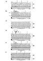
図1は、低透水層の構築方法を分かり易く説明するための模式図である。この図に示すように、本実施形態に係る低透水層の構築方法は、ベントナイト含有造粒物からなる骨材1を撒き出して骨材1の緩詰集合体S1を形成するとともに(図1の(a)参照)、緩詰集合体S1に対して振動を加えて密詰集合体S2を形成し(図1の(b)および(c)参照)、その後、ベントナイト含有造粒物からなる顆粒2を密詰集合体S2の上側から投入して顆粒2を密詰集合体S2中の間隙に充填するとともに(図1の(d)参照)、密詰集合体S2に対して振動を加えることで(図1の(e)参照)、低透水層S3(図1の(f)参照)を構築するというものである。
The best mode for carrying out the present invention will be described in detail with reference to the accompanying drawings.
FIG. 1 is a schematic diagram for easily explaining the construction method of the low water permeability layer. As shown in this figure, the construction method of the low water permeability layer according to the present embodiment scoops out the
すなわち、本実施形態に係る低透水層の構築方法は、大粒径のベントナイト含有造粒物(骨材1)と小粒径のベントナイト含有造粒物(顆粒2)を利用する低透水層の構築方法であって、骨材1を撒き出して骨材1の緩詰集合体S1を形成する撒出し工程と、緩詰集合体S1に対して振動を加えて、緩詰集合体S1よりも間隙比の小さい密詰集合体S2を形成する本加振工程と、顆粒2を密詰集合体S2の上側から投入し、顆粒2を密詰集合体S2中の間隙に充填する充填工程と、充填工程を経た密詰集合体S2に対して振動を加える仕上加振工程とを備えるものである。
That is, the low water-permeable layer construction method according to the present embodiment is a low water-permeable layer using a large particle size bentonite-containing granule (aggregate 1) and a small particle size bentonite-containing granule (granule 2). The construction method includes a step of squeezing the
ベントナイト含有造粒物は、ベントナイトを含有する造粒物である。ベントナイトは、モンモリロナイトを主成分とする粘土の一種であり、水を吸収して膨潤する性質やイオン交換性を備えている。 The bentonite-containing granulated product is a granulated product containing bentonite. Bentonite is a kind of clay mainly composed of montmorillonite, and has a property of absorbing water and swelling and ion exchange.
骨材1の粒径の大きさは、礫に区分される程度の大きさ(2mm以上)であれば特に制限はないが、16mm以上とすることが望ましい。また、骨材1の形状にも制限はないが、球状とすることが望ましい。なお、骨材1の粒度は、均等係数UC(=加積質量比60%に対応する粒径D60/加積質量比10%に対応する粒径D10)が1<UC<5となるように調整することが望ましい。
The size of the particle size of the
顆粒2は、密詰集合体S2中の間隙に充填可能な粒径・形状を有するものであり、骨材1よりも粒径の小さいベントナイト造粒物からなる。骨材1の平均粒径を16mm程度とした場合には、顆粒2の平均粒径を0.5〜0.7mm程度とすることが望ましい。
The
骨材1と顆粒2とで、ベントナイト含有造粒物の配合やベントナイト含有造粒物に含まれるベントナイトの充填乾燥密度を異ならせてもよいが、本実施形態では、同一にしている。
The
低透水層S3において達成すべき骨材1と顆粒2の粒径比(骨材1の平均粒径:顆粒2の平均粒径)、骨材1の重量百分率(=骨材1の単位体積重量/低透水層S3の単位体積重量×100%)、顆粒2の重量百分率(=骨材1の単位体積重量/低透水層S3の単位体積重量×100%)の最適値は、予備試験により設定することが望ましい。予備試験は、前記した各工程を模擬した試験であって、実施工で用いる骨材1および顆粒2と同等のものを使用して行う。
本実施形態では、骨材1と顆粒2の粒径比を16:0.5〜16:0.7、骨材1の重量百分率を70%、顆粒2の重量百分率を30%としている。なお、本実施形態では、骨材1と顆粒2のみで低透水層S3を形成しているので、低透水層S3の単位体積重量は、骨材1の単位体積重量に顆粒2の単位体積重量を加算した値となる。
Particle size ratio of
In the present embodiment, the particle size ratio between the
なお、ベントナイト含有造粒物の配合や充填乾燥密度等は、低透水層S3における目標充填乾燥密度を満足するように決定すればよい。本実施形態では、低透水層S3におけるベントナイトの目標充填乾燥密度ρdを1.6Mg/m3としており、これを満足できるように、ベントナイト含有粒造物中のベントナイトの充填乾燥密度を2.0Mg/m3程度としている。このようなベントナイト含有粒造物は、例えば、100重量部の微粉状ベントナイト(粒径0.001〜0.074)に対して、3〜12重量部の水を混合し、造粒、含水比調整、粒度調整を行うことによって製造する。 In addition, what is necessary is just to determine the mixing | blending, filling dry density, etc. of a bentonite containing granulated material so that the target filling dry density in the low water-permeable layer S3 may be satisfied. In this embodiment, the target filling dry density ρ d of bentonite in the low water permeable layer S3 is set to 1.6 Mg / m 3, and the bentonite filling dry density in the bentonite-containing granule is set to 2.0 Mg so as to satisfy this. / M 3 or so. Such a bentonite-containing granulated product is, for example, mixed with 3 to 12 parts by weight of water with respect to 100 parts by weight of finely powdered bentonite (particle size of 0.001 to 0.074) to adjust granulation and water content ratio. It is manufactured by adjusting the particle size.
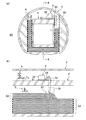
次に、放射性廃棄物の処分施設のピット(構造物)の周囲に人工バリアを形成する場合を例にして、本実施形態に係る低透水層の構築方法をより詳細に説明する。なお、図2は、低透水層の構築方法を分かり易く説明するための模式図であり、骨材1や顆粒2の寸法等は、実際のものと相違する。
Next, the construction method of the low water permeability layer according to the present embodiment will be described in more detail by taking as an example the case where an artificial barrier is formed around a pit (structure) of a radioactive waste disposal facility. FIG. 2 is a schematic diagram for explaining the construction method of the low water permeability layer in an easy-to-understand manner. The dimensions and the like of the
図2に示すように、放射性廃棄物の処分施設のピットPは、トンネルT内に構築されるものであり、人工バリアとなる低透水層S3は、ピットPを取り囲むように形成される。なお、低透水層S3は、トンネルTのインバートとピットPの底版との間、トンネルT内に構築した側壁とピットPの側壁との間、および、ピットPの頂版上に形成されるが、いずれの部位においても、本実施形態に係る低透水層の構築方法を適用することができる。以下では、ピットPの側部に低透水層S3を構築する場合を例示する。 As shown in FIG. 2, the pit P of the radioactive waste disposal facility is constructed in the tunnel T, and the low water permeable layer S3 serving as an artificial barrier is formed so as to surround the pit P. The low water permeable layer S3 is formed between the invert of the tunnel T and the bottom plate of the pit P, between the side wall constructed in the tunnel T and the side wall of the pit P, and on the top plate of the pit P. In any part, the construction method of the low water permeable layer according to the present embodiment can be applied. Below, the case where the low water-permeable layer S3 is built in the side part of the pit P is illustrated.
(撒出し工程)
まず、既に構築した低透水層S3上に骨材1を撒き出するとともに、必要に応じて敷き均し、所定の層厚の緩詰集合体S1を形成する。撒出し厚さは、1m以内の範囲で設定するとよい。骨材1の撒出し方法に制限はなく、例えば、ダンプトラックやブルトーザ等により行ってもよいし、図示したように、ピットPの頂版上を走行可能な撒出し装置3により行ってもよい。ちなみに、撒出し装置3は、走行架台31、受入ホッパ32、ベルトコンベア33、供給フィーダ34、シュート35などを備えて構成されていて、ホイールローダなどの運搬車両4を用いて受入ホッパ32に骨材1を投入すると、ベルトコンベア33、供給フィーダ34およびシュート35を介して既設の低透水層S3上に撒き出されることになる。
(Spreading process)
First, the
(本加振工程)
次に、緩詰集合体S1に対して振動を加える。緩詰集合体S1に対して振動を加えると、間隙比の小さい密詰集合体S2に変化し、乱れの少ない均質な骨格構造が形成されるようになる。なお、緩詰集合体S1は、骨材1,1,…が互いに接触した状態にあるので、振動の伝播効率が高い状態にあり、したがって、微振動を短時間加えただけでも、密詰め状態に変化する。緩詰集合体S1に加える振動の振動数、振幅、一箇所当たりの加振時間等は、骨材1の粒径や目標充填乾燥密度ρdの大きさ等に応じて適宜設定すればよいが、骨材1の平均粒径を16mm、目標充填乾燥密度ρdを1.6Mg/m3とする場合、一箇所当たりの加振時間は5〜15秒程度である。加振方法に制限はなく、緩詰集合体S1上を走行可能な小型の振動ローラ5(図2の(b)参照)にて振動を加えてもよいし、空頭制限のあるような狭隘部等においては、プレートコンパクタ6(図2の(a)参照)にて振動を加えてもよい。加振方向にも制限はないが、好適には、上下方向に加振することが望ましい。
(This vibration process)
Next, vibration is applied to the loosely packed aggregate S1. When vibration is applied to the loosely packed aggregate S1, it changes to a densely packed aggregate S2 with a small gap ratio, and a homogeneous skeletal structure with less disturbance is formed. The loosely packed aggregate S1 is in a state in which the
(充填工程)
続いて、図1の(d)に示すように、顆粒2を密詰集合体S2の上側から投入し、重力の作用により顆粒2を密詰集合体S2中の間隙に充填する。顆粒2の投入方法に制限はなく、例えば、均等に撒き出す機構を備えたダンプトラックやブルトーザ等により行ってもよいし、撒出し装置3(図2参照)により行ってもよい。また、図示は省略するが、トンネルT内に粉体輸送用の配管を設け、当該配管の空気流を利用して顆粒2を粉体輸送してもよい。顆粒2を粉体輸送とすれば、無粉塵に近い環境を確保することが可能となるので、作業環境が良好なものになる。
(Filling process)
Subsequently, as shown in FIG. 1 (d), the
(仕上加振工程)
次に、図1の(e)に示すように、充填工程を経た密詰集合体S2に対して振動を加える。なお、密詰集合体S2に対して振動を加えると、顆粒2の充填密度が高まる関係上、密詰集合体S2の上層部に間隙が発生する場合がある。この場合には、当該間隙に顆粒2を再投入するとともに、必要に応じて振動を加えればよい。なお、加振振動数、振幅、一箇所当たりの加振時間等は、顆粒2の粒径や目標充填乾燥密度ρdの大きさ等に応じて適宜設定すればよいが、顆粒2の平均粒径を0.5mm、目標充填乾燥密度ρdを1.6Mg/m3とする場合、一箇所当たりの加振時間は5〜15秒程度である。加振方法に制限はなく、密詰集合体S2上を走行可能な小型の振動ローラ5(図2の(b)参照)にて振動を加えてもよいし、空頭制限のあるような狭隘部等においては、プレートコンパクタ6(図2の(a)参照)にて振動を加えてもよい。加振方向にも制限はないが、好適には、上下方向に加振することが望ましい。
(Finish vibration process)
Next, as shown in FIG. 1E, vibration is applied to the densely packed assembly S2 that has undergone the filling process. When vibration is applied to the densely packed aggregate S2, a gap may be generated in the upper layer portion of the densely packed aggregate S2 because the packing density of the
なお、本実施形態では、骨材1および顆粒2の重量百分率等が前記した予備試験で設定した値となるように、撒出し工程において70重量部の骨材1を撒き出し、充填工程および仕上加振工程において30重量部の顆粒2を投入する。
In the present embodiment, 70 parts by weight of the
上記の各工程を経ると、透水係数の極めて小さい低透水層S3が形成されることになる。そして、撒出し工程〜仕上加振工程を繰り返すことで、ピットPの周囲に人工バリアが形成されることになる。 Through the above steps, the low water permeability layer S3 having a very low water permeability coefficient is formed. Then, an artificial barrier is formed around the pit P by repeating the brewing process to the finishing vibration process.
以上説明した本実施形態に係る低透水層の構築方法によれば、乱れの少ない均質な骨格構造(密詰集合体S2)を形成されるとともに、顆粒2が最密充填されるようになるので、低透水層S3の品質(充填乾燥密度や透水係数等)にばらつきが生じ難くなる。また、施工法がシンプルであることから、現場での品質管理が容易になるとともに、再現性が高いことから、施工条件の設定等を試験室にて行うことも可能となる。
According to the construction method of the low water permeability layer according to the present embodiment described above, a homogeneous skeletal structure (densely packed aggregate S2) with less turbulence is formed, and the
また、大型の転圧機等を用いて力任せに緩詰集合体S1の間隙比を小さくすると、大きな側圧が発生してピットPに影響を及ぼす虞があるが、本実施形態に係る低透水層の構築方法は、振動エネルギーを利用して間隙比を小さくするものであるから、大きな側圧が発生することはなく、したがって、ピットPに与える影響も小さいものとなる。 In addition, if the gap ratio of the loosely packed assembly S1 is reduced by force using a large compactor or the like, a large lateral pressure may be generated and affect the pit P. However, the construction of the low water permeability layer according to the present embodiment is possible. Since the method uses the vibration energy to reduce the gap ratio, a large side pressure is not generated, and therefore the influence on the pit P is small.
また、本実施形態によれば、既往の施工機械や設備を利用することができ、特殊な施工機械等を必要としないので、低コスト化を図ることが可能となる。しかも、大型の重機を必ずしも必要としないので、狭隘な空間においても、高品質の低透水層S3を構築することが可能となる。 In addition, according to the present embodiment, existing construction machines and equipment can be used, and a special construction machine or the like is not required, so that the cost can be reduced. In addition, since a large heavy machine is not necessarily required, it is possible to construct a high quality low water permeable layer S3 even in a narrow space.
加えて、本実施形態によれば、骨材1および顆粒2をベントナイト含有造粒物にて形成しているので、作業空間に粉塵が充満するようなことはなく、良好な作業空間を確保することが可能となる。
In addition, according to the present embodiment, since the
また、本実施形態では、顆粒2を投入した後に、顆粒2が充填された密詰集合体S2に対して振動を加えているので、顆粒2の充填密度が高まることになり、ひいては、低透水層S3の充填乾燥密度が高いものとなる。
Moreover, in this embodiment, since vibration is applied to the densely packed aggregate S2 filled with the
ちなみに、低透水層S3におけるベントナイトの充填乾燥密度ρと加振時間との関係は、表1のようになる。 Incidentally, the relationship between the bentonite filling dry density ρ in the low water permeable layer S3 and the vibration time is as shown in Table 1.
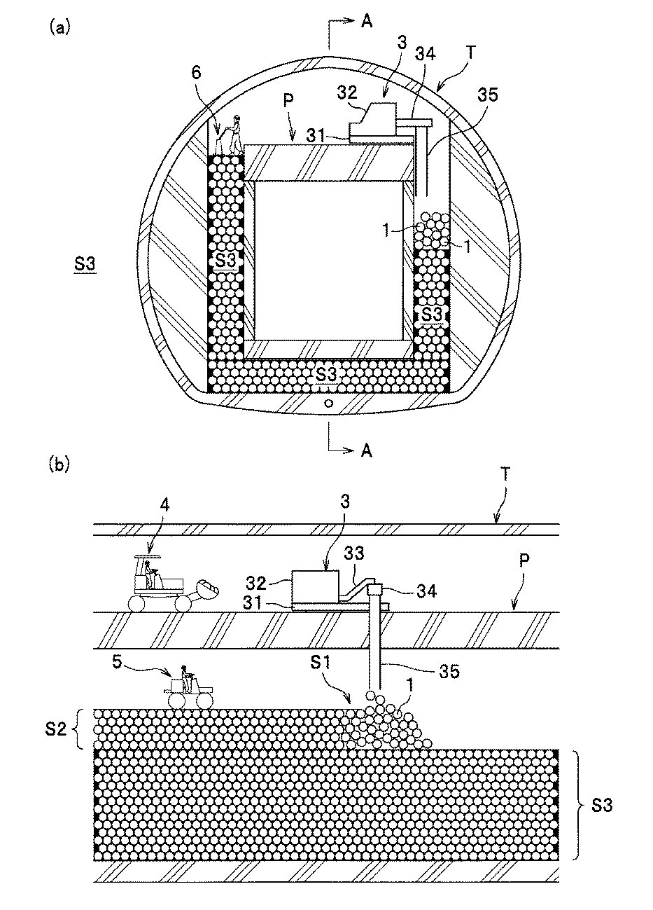
表1から分かるように、本加振の加振時間が長くなるに従って充填乾燥密度ρが大きくなる傾向にあり、本加振の加振時間が同じであれば、仕上加振の加振時間が長くなるに従って充填乾燥密度ρが大きくなる傾向にある。なお、本加振の加振時間を5秒とした場合であっても、品質にばらつきのない低透水層S3を得ることができるが、本加振の加振時間を10秒以上とすると、仕上加振の加振時間の長短が充填乾燥密度ρに及ぼす影響が小さいものとなるので、より一層品質にばらつきのない低透水層S3を得ることができる。 As can be seen from Table 1, the filling dry density ρ tends to increase as the excitation time of the main excitation becomes longer. If the excitation time of the main excitation is the same, the excitation time of the final excitation is the same. As the length increases, the filling dry density ρ tends to increase. In addition, even when the excitation time of the main excitation is 5 seconds, it is possible to obtain a low water permeability layer S3 with no variation in quality, but when the excitation time of the main excitation is 10 seconds or more, Since the effect of the finish excitation time on the filling and drying density ρ is small, the low water permeability layer S3 with no further variation in quality can be obtained.
なお、前記した実施形態では、所定量の骨材1を撒き出した後に、緩詰集合体S1に振動を加える場合を例示したが、骨材1を撒き出しながら、緩詰集合体S1に振動を加えてもよい。
In the above-described embodiment, the case where vibration is applied to the loosely packed aggregate S1 after the predetermined amount of
また、前記した実施形態では、所定量の顆粒2を投入した後に、密詰集合体S2に振動を加える場合を例示したが、密詰集合体S2に振動を加えながら、顆粒2を投入してもよい。また、表1からも分かるように、仕上加振を省略しても差し支えない。
In the above-described embodiment, the case where vibration is applied to the densely packed aggregate S2 after the predetermined amount of
1 骨材
2 顆粒
S1 緩詰集合体
S2 密詰集合体
S3 低透水層
1
Claims (5)
前記緩詰集合体に対して振動を加えて、前記緩詰集合体よりも間隙比の小さい密詰集合体を形成する本加振工程と、
前記骨材よりも粒径の小さいベントナイト含有粒状物からなる顆粒を前記密詰集合体の上側から投入して前記顆粒を前記密詰集合体中の間隙に充填する充填工程と、を含むことを特徴とする低透水層の構築方法。 Squeezing out an aggregate composed of bentonite-containing particulates to form a loosely packed aggregate of the aggregate;
Applying the vibration to the loosely packed aggregate to form a tightly packed aggregate having a smaller gap ratio than the loosely packed aggregate; and
Filling a granule made of bentonite-containing granular material having a particle size smaller than that of the aggregate from the upper side of the densely packed aggregate, and filling the granules into the gaps in the densely packed aggregate. A method for constructing a low water permeability layer.
Priority Applications (1)
| Application Number | Priority Date | Filing Date | Title |
|---|---|---|---|
| JP2008082339A JP5113579B2 (en) | 2008-03-27 | 2008-03-27 | Construction method of low permeability layer |
Applications Claiming Priority (1)
| Application Number | Priority Date | Filing Date | Title |
|---|---|---|---|
| JP2008082339A JP5113579B2 (en) | 2008-03-27 | 2008-03-27 | Construction method of low permeability layer |
Publications (2)
| Publication Number | Publication Date |
|---|---|
| JP2009233558A JP2009233558A (en) | 2009-10-15 |
| JP5113579B2 true JP5113579B2 (en) | 2013-01-09 |
Family
ID=41248211
Family Applications (1)
| Application Number | Title | Priority Date | Filing Date |
|---|---|---|---|
| JP2008082339A Active JP5113579B2 (en) | 2008-03-27 | 2008-03-27 | Construction method of low permeability layer |
Country Status (1)
| Country | Link |
|---|---|
| JP (1) | JP5113579B2 (en) |
Families Citing this family (7)
| Publication number | Priority date | Publication date | Assignee | Title |
|---|---|---|---|---|
| JP5789467B2 (en) * | 2011-09-29 | 2015-10-07 | 大成建設株式会社 | Method for compacting the granulated product |
| JP5937909B2 (en) * | 2012-07-20 | 2016-06-22 | 大成建設株式会社 | Granulation compaction method and artificial barrier |
| JP6153189B2 (en) * | 2012-11-28 | 2017-06-28 | 株式会社安藤・間 | Construction method of low permeability layer structure of waste disposal facility |
| JP6152976B2 (en) * | 2013-06-26 | 2017-06-28 | 清水建設株式会社 | Water-absorbing expansive clay material filling device |
| FR3030611B1 (en) * | 2014-12-18 | 2017-01-20 | Agence Nat Pour La Gestion Des Dechets Radioactifs | METHOD FOR FILLING HOLES IN A UNDERGROUND WASTE STORAGE GALLERY |
| JP6226212B2 (en) * | 2016-11-11 | 2017-11-08 | 清水建設株式会社 | Filling method of water-swellable clay material |
| JP6296309B2 (en) * | 2016-11-11 | 2018-03-20 | 清水建設株式会社 | Filling method of water-swellable clay material |
Family Cites Families (8)
| Publication number | Priority date | Publication date | Assignee | Title |
|---|---|---|---|---|
| JPS60119500A (en) * | 1983-11-30 | 1985-06-26 | 三井建設株式会社 | Method of cushioning nuclear waste vessel |
| JPH07294698A (en) * | 1994-04-27 | 1995-11-10 | Ishikawajima Harima Heavy Ind Co Ltd | Method for geological disposal of radioactive waste |
| JPH1076238A (en) * | 1996-09-03 | 1998-03-24 | Kajima Corp | Impermeable layer of waste disposal site and its construction method |
| JP2000325907A (en) * | 1999-05-24 | 2000-11-28 | Taisei Corp | Impervious material and method for constructing impervious layer |
| JP2001096249A (en) * | 1999-09-29 | 2001-04-10 | Shimizu Corp | Structure and construction method of impermeable layer |
| JP3539928B2 (en) * | 2000-06-28 | 2004-07-07 | 株式会社神戸製鋼所 | Buried facility and its construction method, molded body used for it |
| JP2003255087A (en) * | 2002-03-04 | 2003-09-10 | Shimizu Corp | Compaction method of high density bentonite barrier on site |
| JP2007319732A (en) * | 2006-05-30 | 2007-12-13 | Shimizu Corp | Gap filling material and water shielding method |
-
2008
- 2008-03-27 JP JP2008082339A patent/JP5113579B2/en active Active
Also Published As
| Publication number | Publication date |
|---|---|
| JP2009233558A (en) | 2009-10-15 |
Similar Documents
| Publication | Publication Date | Title |
|---|---|---|
| JP5113579B2 (en) | Construction method of low permeability layer | |
| Liu et al. | Particle size ratio and distribution effects on packing behaviour of crushed GMZ bentonite pellets | |
| Zhang et al. | Influences of PSD curve and vibration on the packing dry density of crushed bentonite pellet mixtures | |
| JP5379893B1 (en) | Construction filler | |
| Liu et al. | Investigation on vibration induced segregation behaviour of crushed GMZ bentonite pellet mixtures | |
| JP5536260B2 (en) | Construction filler | |
| Ghazavi et al. | Optimization of aspect ratio of waste tire shreds in sand-shred mixtures using CBR tests | |
| JP2013136938A (en) | Underground continuous water barrier method | |
| JP2002082196A (en) | Buried facility and its construction method, molded body used for it | |
| Lim et al. | A study on the pelletizing condition for roll compaction of powdered radioactive wastes | |
| Marjavaara et al. | Filling the gap between buffer and rock in the deposition hole | |
| CN106092697A (en) | The draining consolidating apparatus of a kind of soil sample and preparation method | |
| JP2004285605A (en) | Construction method of structure with kneaded material containing large amount of coal ash | |
| JP2005238175A (en) | Granular bentonite impermeable material, impermeable structure and construction method thereof | |
| JP2013220949A (en) | Method for manufacturing coal ash workpiece and manufacturing system | |
| KR102061297B1 (en) | Volume reduction unit and method for radioactive waste by compaction | |
| JP2005146609A (en) | Ground improving method | |
| JP3690624B2 (en) | Placing kneaded material containing a large amount of coal ash | |
| JP3375559B2 (en) | Self-propelled soil improvement machine | |
| RU2074286C1 (en) | Method for compacting in filling | |
| CN206578031U (en) | Efficient sandstone screening plant | |
| JP2654157B2 (en) | Underwater embankment material and method of manufacturing the same | |
| JP6249473B2 (en) | Construction method of water shielding material and water shielding layer | |
| JP4625333B2 (en) | Fluidized soil and fluidized method | |
| JP4359436B2 (en) | Method for producing soil mortar |
Legal Events
| Date | Code | Title | Description |
|---|---|---|---|
| A621 | Written request for application examination |
Free format text: JAPANESE INTERMEDIATE CODE: A621 Effective date: 20101108 |
|
| A977 | Report on retrieval |
Free format text: JAPANESE INTERMEDIATE CODE: A971007 Effective date: 20110920 |
|
| A131 | Notification of reasons for refusal |
Free format text: JAPANESE INTERMEDIATE CODE: A131 Effective date: 20111004 |
|
| A521 | Request for written amendment filed |
Free format text: JAPANESE INTERMEDIATE CODE: A523 Effective date: 20111202 |
|
| TRDD | Decision of grant or rejection written | ||
| A01 | Written decision to grant a patent or to grant a registration (utility model) |
Free format text: JAPANESE INTERMEDIATE CODE: A01 Effective date: 20120918 |
|
| A01 | Written decision to grant a patent or to grant a registration (utility model) |
Free format text: JAPANESE INTERMEDIATE CODE: A01 |
|
| A61 | First payment of annual fees (during grant procedure) |
Free format text: JAPANESE INTERMEDIATE CODE: A61 Effective date: 20121012 |
|
| FPAY | Renewal fee payment (event date is renewal date of database) |
Free format text: PAYMENT UNTIL: 20151019 Year of fee payment: 3 |
|
| R150 | Certificate of patent or registration of utility model |
Ref document number: 5113579 Country of ref document: JP Free format text: JAPANESE INTERMEDIATE CODE: R150 Free format text: JAPANESE INTERMEDIATE CODE: R150 |
|
| R250 | Receipt of annual fees |
Free format text: JAPANESE INTERMEDIATE CODE: R250 |
|
| R250 | Receipt of annual fees |
Free format text: JAPANESE INTERMEDIATE CODE: R250 |
|
| R250 | Receipt of annual fees |
Free format text: JAPANESE INTERMEDIATE CODE: R250 |
|
| R250 | Receipt of annual fees |
Free format text: JAPANESE INTERMEDIATE CODE: R250 |
|
| R250 | Receipt of annual fees |
Free format text: JAPANESE INTERMEDIATE CODE: R250 |
|
| R250 | Receipt of annual fees |
Free format text: JAPANESE INTERMEDIATE CODE: R250 |
|
| R250 | Receipt of annual fees |
Free format text: JAPANESE INTERMEDIATE CODE: R250 |
|
| R250 | Receipt of annual fees |
Free format text: JAPANESE INTERMEDIATE CODE: R250 |
|
| R250 | Receipt of annual fees |
Free format text: JAPANESE INTERMEDIATE CODE: R250 |