JP5113909B2 - Placement of graphics objects on the page with control based on relative position - Google Patents
Placement of graphics objects on the page with control based on relative position Download PDFInfo
- Publication number
- JP5113909B2 JP5113909B2 JP2010527953A JP2010527953A JP5113909B2 JP 5113909 B2 JP5113909 B2 JP 5113909B2 JP 2010527953 A JP2010527953 A JP 2010527953A JP 2010527953 A JP2010527953 A JP 2010527953A JP 5113909 B2 JP5113909 B2 JP 5113909B2
- Authority
- JP
- Japan
- Prior art keywords
- layout
- graphics object
- page
- graphics
- user
- Prior art date
- Legal status (The legal status is an assumption and is not a legal conclusion. Google has not performed a legal analysis and makes no representation as to the accuracy of the status listed.)
- Expired - Fee Related
Links
Images












Classifications
-
- G—PHYSICS
- G06—COMPUTING OR CALCULATING; COUNTING
- G06Q—INFORMATION AND COMMUNICATION TECHNOLOGY [ICT] SPECIALLY ADAPTED FOR ADMINISTRATIVE, COMMERCIAL, FINANCIAL, MANAGERIAL OR SUPERVISORY PURPOSES; SYSTEMS OR METHODS SPECIALLY ADAPTED FOR ADMINISTRATIVE, COMMERCIAL, FINANCIAL, MANAGERIAL OR SUPERVISORY PURPOSES, NOT OTHERWISE PROVIDED FOR
- G06Q50/00—Information and communication technology [ICT] specially adapted for implementation of business processes of specific business sectors, e.g. utilities or tourism
- G06Q50/10—Services
-
- G—PHYSICS
- G06—COMPUTING OR CALCULATING; COUNTING
- G06F—ELECTRIC DIGITAL DATA PROCESSING
- G06F40/00—Handling natural language data
- G06F40/10—Text processing
- G06F40/103—Formatting, i.e. changing of presentation of documents
- G06F40/106—Display of layout of documents; Previewing
-
- G—PHYSICS
- G06—COMPUTING OR CALCULATING; COUNTING
- G06F—ELECTRIC DIGITAL DATA PROCESSING
- G06F9/00—Arrangements for program control, e.g. control units
- G06F9/06—Arrangements for program control, e.g. control units using stored programs, i.e. using an internal store of processing equipment to receive or retain programs
- G06F9/44—Arrangements for executing specific programs
- G06F9/451—Execution arrangements for user interfaces
Landscapes
- Engineering & Computer Science (AREA)
- Theoretical Computer Science (AREA)
- Business, Economics & Management (AREA)
- Software Systems (AREA)
- General Physics & Mathematics (AREA)
- Physics & Mathematics (AREA)
- Tourism & Hospitality (AREA)
- General Health & Medical Sciences (AREA)
- Health & Medical Sciences (AREA)
- General Engineering & Computer Science (AREA)
- General Business, Economics & Management (AREA)
- Economics (AREA)
- Human Resources & Organizations (AREA)
- Marketing (AREA)
- Primary Health Care (AREA)
- Strategic Management (AREA)
- Human Computer Interaction (AREA)
- Audiology, Speech & Language Pathology (AREA)
- Computational Linguistics (AREA)
- Artificial Intelligence (AREA)
- Processing Or Creating Images (AREA)
- Document Processing Apparatus (AREA)
Description
[関連出願の相互参照]
本願は、下記の同時係属出願にも関連し、各出願は、参照により本明細書に援用される。
・2003年9月30日に出願された米国特許出願第10/675,724号
・2003年9月30日に出願された米国特許出願第10/675,823号
・2005年5月12日に出願された米国特許出願第11/127,326号
・2005年5月12日に出願された米国特許出願第11/128,543号
・2004年4月23日に出願された米国特許出願第10/831,436号
・2005年4月15日に出願された米国特許出願第11/126,637号
・2005年6月10日に出願された米国特許出願第11/151,167号
・2005年3月1日に出願された米国特許出願第11/069,512号
・2004年11月12日に出願された米国特許出願第10/987,288号
・2006年3月1日に出願された米国特許出願第11/364,933号
・2007年6月27日に出願された米国特許出願第11/769,671号
[Cross-reference of related applications]
This application is also related to the following co-pending applications, each application incorporated herein by reference:
・ US Patent Application No. 10 / 675,724 filed on September 30, 2003 ・ US Patent Application No. 10 / 675,823 filed on September 30, 2003 ・ On May 12, 2005 U.S. Patent Application No. 11 / 127,326, filed on May 12, 2005 U.S. Patent Application No. 11 / 128,543, filed on April 23, 2004 US Patent Application No. 11 / 126,637 filed on April 15, 2005, US Patent Application No. 11 / 151,167 filed on June 10, 2005 US Patent Application No. 11 / 069,512 filed on March 1, US Patent Application No. 10 / 987,288 filed on November 12, 2004, filed March 1, 2006 USA Was filed in the Patent Application No. 11 / 364,933 and issues, and June 27, 2007, US patent application Ser. No. 11 / 769,671
人、及び組織は、静止画像、テキスト、グラフィック、アニメーショングラフィック、及びフルモーションビデオ画像のような大量のデジタル画像コンテンツを急速に蓄積している。これらのコンテンツは、個別に表現される場合もあれば、文書、カタログ、プレゼンテーション、静止画写真、商用ビデオ、家庭用ビデオ、及び1以上の関連デジタルコンテンツファイルを表すメタデータといったように、広く様々な形で結合される場合もある。こうした収集物の数が増加し、その多様性が増加するのに従って、人、及び組織は、デジタルコンテンツを自分達の収集物として編集、及び表現するシステム、及び方法を益々必要としている。この要求を満たすために、デジタル画像コンテンツを編集、及び表示するための種々のシステム、及び方法が提案されている。 Humans and organizations are rapidly accumulating large amounts of digital image content such as still images, text, graphics, animated graphics, and full motion video images. These contents may be expressed individually or vary widely, such as metadata representing documents, catalogs, presentations, still pictures, commercial videos, home videos, and one or more related digital content files. In some cases, they may be combined in any way. As the number of these collections increases and their diversity increases, people and organizations increasingly require systems and methods for editing and representing digital content as their collections. In order to meet this requirement, various systems and methods have been proposed for editing and displaying digital image content.
例えば、ユーザがデジタルフォトアルバムを手作業で作成することが可能な幾つかの手動型のデジタル画像アルバム化システムが存在する。こうしたシステムは一般に、多数の画像を編集し、画像を1以上のページ上にレイアウトするツールを提供する。中でもデジタルフォトアルバムを手作業で作成する一般的タイプのツールは、多数の画像の中からアルバムの1ページに表示される一部の画像を選択するツール、ページ上の画像を手動で再配置するためのグラフィカルユーザインタフェース、及び、アルバムに表示される画像のサイズ、及び向きのような種々の特徴を変更するための基本的な画像編集ツールである。ユーザは通常、完全手動型のデジタル画像アルバム化システムを使用してデジタルフォトアルバムを作成するプロセスが、退屈で、時間を要するものであることを知っている。 For example, there are several manual digital image albuming systems that allow a user to manually create a digital photo album. Such systems typically provide tools for editing a large number of images and laying out the images on one or more pages. Among them, a general type of tool for manually creating a digital photo album is a tool for selecting a part of images displayed on one page of an album from a large number of images, and manually rearranging images on the page. And a basic image editing tool for changing various features such as the size and orientation of images displayed in an album. Users typically know that the process of creating a digital photo album using a fully manual digital image albuming system is tedious and time consuming.
一部の自動化されたデジタル画像アルバム化システムによれば、ユーザは、画像に関連するメタデータとして指定された日付や時刻に従ってデジタル画像をアルバムページとして編集することが出来る。こうしたシステムによれば、一般にユーザは、デジタルフォトアルバムに表示される画像に注釈を付けることも出来る。自動化されたデジタル画像アルバム化システムによっては、種々の所定のレイアウトテンプレートを備え、ユーザは、そうしたレイアウトテンプレートを選択し、デジタルフォトアルバムを作成出来る場合がある。こうしたシステムでは、ユーザが、多数の画像の中から幾つかの画像を選択されたレイアウトテンプレート上の種々の所定の画像位置に割当てると、システムは、それらの画像のサイズ、位置、回転、及び枠組みを、選択されたテンプレート上の種々の所定の画像位置について指定されたパラメタに従って自動的に調節する。 Some automated digital image albuming systems allow a user to edit a digital image as an album page according to the date and time specified as metadata associated with the image. Such systems generally allow a user to annotate images displayed on a digital photo album. Some automated digital image albuming systems include various predetermined layout templates, and the user may be able to select such layout templates and create a digital photo album. In such a system, when a user assigns several images from a large number of images to various predetermined image positions on a selected layout template, the system can determine the size, position, rotation, and framework of those images. Are automatically adjusted according to the specified parameters for various predetermined image positions on the selected template.
デジタル画像アルバム化システムの中には、ユーザからの最小限の入力で、アルバムページを自動的に生成するように設計されるものがある。そのようなシステムの一つとして、ページ作成器モジュール、及び画像配置モジュールが挙げられる。ページ作成器モジュールは、多数の画像を、第1の遺伝進化アルゴリズムに基いてアルバムページに割当てる。画像配置モジュールは、所与のページに割当てられた画像についてのページレイアウトの遺伝構造を、第2の遺伝進化アルゴリズムに基いて生成する。これらの遺伝構造は、所与のページに配置される画像の位置、縮尺、及び回転姿勢を決定する。ページレイアウト発生器モジュールは、それらのレイアウトを特定の他の好み、及びページ要件と比較する。適当なレイアウトが生成されると、最終的なアルバムレイアウトは表示され、印刷され、又は後の使用に備えて転送される場合がある。 Some digital image albuming systems are designed to automatically generate album pages with minimal input from the user. One such system includes a page creator module and an image placement module. The page creator module assigns multiple images to the album page based on the first genetic evolution algorithm. The image placement module generates a page layout genetic structure for an image assigned to a given page based on the second genetic evolution algorithm. These genetic structures determine the position, scale, and rotational orientation of the image placed on a given page. The page layout generator module compares their layout with certain other preferences and page requirements. Once a suitable layout is generated, the final album layout may be displayed, printed, or transferred for later use.
他の自動デジタル画像アルバム化システムとしては、イベントによって編集され、一組のアルバム化パラメタに基いて自動的にレイアウトされたアルバムをユーザに対し表示する、ページレイアウトモジュールを含むものがある。1ページ上にレイアウトされる画像の数は、パラメトリック法によって決定され、又は画像の属性の分析によって決定される。パラメトリック法は、1ページを一組の正方格子に分割し、1ページ上にレイアウトされる画像の数を、画像をそれらの正方格子上にレイアウトするための一組の規則に基いて決定する。このシステムでは、ページ上の画像の実際のレイアウトは、画像のサイズのような画像の属性を一組のテンプレートに適合させることによって決定される場合がある。 Other automatic digital image albuming systems include a page layout module that displays to the user an album that has been edited by an event and automatically laid out based on a set of albuming parameters. The number of images laid out on a page is determined by a parametric method or by analysis of image attributes. The parametric method divides a page into a set of square lattices and determines the number of images laid out on a page based on a set of rules for laying out images on those square lattices. In this system, the actual layout of the image on the page may be determined by adapting image attributes, such as image size, to a set of templates.
さらに他の自動デジタル画像アルバム化システムは、各画像が同じページ上に配置される他の画像に対して力を加えることを仮定する力学モデルに基いて、画像をページ上に自動的に位置決めする場合がある。力は、画像間を隔てる距離の関数である。システムは、各画像をその画像に対して加わる総合的な力の向きにその総合的な力の関数として決まる距離だけ動かすことによって、ページ上の画像の初期レイアウトを変更する。 Still other automatic digital image albuming systems automatically position images on a page based on a dynamic model that assumes that each image applies a force to other images placed on the same page. There is a case. The force is a function of the distance separating the images. The system changes the initial layout of the images on the page by moving each image by a distance determined as a function of the total force in the direction of the total force applied to the image.
グラフィックスオブジェクトをページ上に自動的に配置するシステム、及び方法であって、各レイアウトにおけるグラフィックスオブジェクトのうちの1以上の相対位置についての明確な好みによって管理され、又は制御されることが可能なものが必要とされている。 A system and method for automatically placing graphics objects on a page, which can be managed or controlled by a clear preference for the relative position of one or more of the graphics objects in each layout Something is needed.
[概要]
一態様において、本発明は、どのグラフィックスオブジェクトのユーザ指定レイアウトを受け取ったかに応じた方法を特徴とする。ユーザ指定レイアウトから、相対レイアウト仕様が導出される。相対レイアウト仕様は、グラフィックスオブジェクトの相対位置を表す。グラフィックスオブジェクトの最終レイアウトは、相対レイアウト仕様に従って決定される。最終レイアウトは、ページ上のグラフィックスオブジェクトのサイズ寸法、及び位置の仕様を含む。グラフィックスオブジェクトの最終レイアウトは、出力される。
[Overview]
In one aspect, the invention features a method depending on which graphics object a user-specified layout is received. A relative layout specification is derived from the user-specified layout. The relative layout specification represents the relative position of the graphics object. The final layout of the graphics object is determined according to the relative layout specification. The final layout includes the size and location specifications of the graphics objects on the page. The final layout of the graphics object is output.
本発明は、上に記載した方法を実施するように構成された装置、及び上に記載した方法をコンピュータに実施させるためのコンピュータ読取可能命令を記憶するコンピュータ読取可能媒体をさらに特徴とする。 The invention further features an apparatus configured to perform the method described above and a computer readable medium storing computer readable instructions for causing a computer to perform the method described above.
本発明の他の特徴、及び利点は、図面、及び特許請求の範囲の記載を含めて、下記の説明から明らかになるであろう。 Other features and advantages of the invention will be apparent from the following description, including the drawings and the claims.
[詳細な説明]
下記の説明において、同じ参照符号は、同じ要素を識別するために使用される。また、図面は、例示的実施形態の主な特徴を概略的に示すことを意図している。図面は、実際の実施形態のあらゆる特徴を示すことを意図するものでも、描かれた要素の相対的寸法を示すことを意図するものでもなく、原寸どおりに描かれてもいない。
[Detailed description]
In the following description, the same reference numerals are used to identify the same elements. The drawings are also intended to schematically illustrate the main features of an exemplary embodiment. The drawings are not intended to illustrate every feature of the actual embodiment, nor are they intended to illustrate the relative dimensions of the depicted elements, and are not drawn to scale.
1.序論
本明細書において詳細に説明される種々の実施形態は、グラフィックスオブジェクトを1以上のページ上に配置する種々の方法を提供する。これらの実施形態は、各レイアウト(又は、配置)におけるグラフィックスオブジェクトの相対位置についての明確な好みによって管理され、又は制御されることができる。同時に、それらの実施形態は、それらの好みから、指定された設計上の制限(例えば、ページサイズ、マージン、及びガッター余白制限)に従ったグラフィックスオブジェクトの最終レイアウトを自動生成することができる。このように、ユーザは、より専門的に、かつより美術的に美しい形でクリーナを表示しながら、それらの実施形態を、ユーザのグラフィックスオブジェクト配置の一般的な好みに合致するグラフィックスオブジェクトの特定のレイアウトへと誘導することができる。
1. Introduction The various embodiments described in detail herein provide various methods for placing graphics objects on one or more pages. These embodiments can be managed or controlled by a clear preference for the relative position of graphics objects in each layout (or arrangement). At the same time, those embodiments can automatically generate a final layout of graphics objects from their preferences according to specified design constraints (eg, page size, margin, and gutter margin limitations). In this way, the user can view those cleaners in a more professional and more aesthetically pleasing manner, while allowing those embodiments to match the general preference of the user's graphics object placement. You can be guided to a specific layout.
本明細書において、「ページ」という用語は、その上にグラフィックスオブジェクトをレイアウトすることが可能な任意のタイプの独立した領域を意味し、例えば、グラフィックスオブジェクトを印刷することが可能な独立した物理媒体として実施される物理的ページ(例えば、一片の用紙)、及び例えば電子表示装置によりユーザに対して表示することが可能なグラフィックスオブジェクトのレイアウトを含む仮想的、デジタル的、又は電子的なページを含む。 In this specification, the term “page” means any type of independent area on which a graphics object can be laid out, for example, an independent area on which a graphics object can be printed. Virtual, digital, or electronic, including a physical page implemented as a physical medium (eg, a piece of paper) and a layout of graphics objects that can be displayed to a user, eg, by an electronic display device Includes pages.
「グラフィックスオブジェクト」という用語は、物理的ページ、又は仮想的ページ上に描画することが可能な任意のタイプの視覚的に知覚可能なコンテンツを幅広く意味し、例えば、画像、及びテキストを含む。画像ベースのグラフィックスオブジェクト(又は、単に「画像」)は、任意のタイプのデジタル画像、又は電子画像であってよく、完全な画像であっても、部分的な画像であってもよく、例えば、画像センサ(例えば、ビデオカメラ、静止画カメラ、又は光学スキャナ)により撮影された画像、又はそのような画像を処理(フィルタリング、再整形、拡大、若しくはその他変更)したもの、テキスト画像(例えば、テキストを含むビットマップ画像)、及び図形的画像を含む。「グラフィックスオブジェクト」という用語は、単一要素グラフィックスオブジェクトと、1以上のグラフィックスオブジェクトの団結グループ、又は集まりから形成されるマルチ要素グラフィックスオブジェクトとの両方を包含する。特定のマルチ要素グラフィックスオブジェクトに対する単一要素グラフィックスオブジェクトの割当ては、構成要素となる複数の単一要素グラフィックスオブジェクトを互いに関連付けることを意味する。一般に、マルチ要素グラフィックスオブジェクトに含まれる複数の単一要素グラフィックスオブジェクトは、同じタイプのものであってもよいし、異なるタイプのものであってもよい。グラフィックスオブジェクトは通常、1以上のコンピュータ読取可能媒体上の1以上のデータベースに記憶される。 The term “graphics object” broadly refers to any type of visually perceptible content that can be rendered on a physical page or a virtual page and includes, for example, images and text. An image-based graphics object (or simply “image”) may be any type of digital or electronic image, and may be a complete image or a partial image, eg Images taken by image sensors (eg video cameras, still cameras or optical scanners) or processed (filtered, reshaped, magnified or otherwise modified) of such images, text images (eg A bitmap image including text) and a graphic image. The term “graphics object” encompasses both single-element graphics objects and multi-element graphics objects formed from a united group or collection of one or more graphics objects. Assigning a single element graphics object to a particular multi-element graphics object means associating a plurality of constituent single element graphics objects with each other. In general, multiple single element graphics objects included in a multi-element graphics object may be of the same type or of different types. Graphics objects are typically stored in one or more databases on one or more computer readable media.
一部の実施形態において、画像ベースのグラフィックスオブジェクト(例えば、写真のような画像)は、固定面積画像として指定される場合もあれば、可変面積画像として指定される場合もある。これらの実施形態では、固定面積画像の面積やサイズが、生成されるレイアウトにおいて変更されることはないが、可変面積画像のサイズを変更することは許される。可変面積画像は、同じページ上に描画される画像の相対面積に関して制限を有する場合もあれば、有しない場合もある。 In some embodiments, an image-based graphics object (eg, an image such as a photograph) may be designated as a fixed area image or a variable area image. In these embodiments, the area and size of the fixed area image are not changed in the generated layout, but it is allowed to change the size of the variable area image. A variable area image may or may not have a limit on the relative area of images drawn on the same page.
例示的実施形態として、画像ベースのグラフィックスオブジェクトはそれぞれ、個別のアスペクト比を有する。アスペクト比は、画像の幅に対する画像の高さの比として定義される。各可変面積画像には、正のスカラー値の公称サイズが割当てられる場合がある。「公称サイズ」とは、指定サイズ、又は理論上のサイズを意味し、公称サイズは、実際のサイズ、すなわち描画されるサイズとは異なる場合もあれば、異ならない場合もある。グラフィックスオブジェクトの「サイズ」とは、そのグラフィックスオブジェクトが占めるページ上の面積の大きさを意味する。実施形態によっては、ユーザは、画像に割当てられる公称サイズ値を設定することが出来る場合がある。他の実施形態において、グラフィックスオブジェクト配置システムは、公称サイズ値をグラフィックスオブジェクトに自動的に割当てる場合がある。 As an exemplary embodiment, each image-based graphics object has a distinct aspect ratio. The aspect ratio is defined as the ratio of the image height to the image width. Each variable area image may be assigned a nominal size of a positive scalar value. “Nominal size” means a specified size, or theoretical size, which may or may not be the actual size, ie, the drawn size. The “size” of a graphics object means the size of the area on the page occupied by the graphics object. In some embodiments, the user may be able to set a nominal size value assigned to the image. In other embodiments, the graphics object placement system may automatically assign a nominal size value to the graphics object.
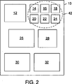
図1は、複数の単一要素グラフィックスオブジェクト12〜32を含むページ10の一例を示している。
FIG. 1 illustrates an example of a
図2に示すように、単一要素グラフィックスオブジェクト12〜32のうちの選択されたものは、グラフィックスオブジェクト42としてグループ化される場合があり、グラフィックスオブジェクト42を構成するグラフィックスオブジェクト(すなわち、14〜24)は、ページ上のグラフィックスオブジェクトのレイアウトにおいて、互いに近くに表示されることを意図している。図2に示す例において、マルチ要素グラフィックスオブジェクト42は、異なるタイプの複数の単一要素グラフィックスオブジェクト(例えば、画像ベースのグラフィックスオブジェクトとテキストのグラフィックスオブジェクト)を含む場合がある。また、マルチ要素グラフィックスオブジェクトの単一要素グラフィックスオブジェクトは、自由に配置される場合もあれば、特定の順序(例えば、ビデオクリップのキーフレームの一時的な並び順序)で配置される場合もある。他のいずれのグラフィックスオブジェクトとの間にも密接な関係を有しない単一要素グラフィックスオブジェクトは、単一の表現形態しか持たない「退化」グラフィックスオブジェクトである。 As shown in FIG. 2, selected ones of single element graphics objects 12-32 may be grouped as graphics objects 42, and the graphics objects that make up graphics objects 42 (ie, 14-24) are intended to be displayed close to each other in the layout of graphics objects on the page. In the example shown in FIG. 2, the multi-element graphics object 42 may include multiple types of single-element graphics objects (eg, image-based graphics objects and text graphics objects). In addition, single element graphics objects of multi-element graphics objects may be arranged freely, or may be arranged in a specific order (for example, a temporary arrangement order of key frames of a video clip). is there. A single element graphics object that does not have a close relationship with any other graphics object is a “degenerate” graphics object that has only a single representation.
図3A〜図3Dに示すように、構成要素として2以上のグラフィックスオブジェクトを含むグラフィックスオブジェクト52は、2以上の方法(すなわち、配置)で表示することができる。実施形態によっては、マルチ要素グラフィックスオブジェクトにおける単一要素グラフィックスオブジェクトの表示は、グラフィックスオブジェクトの水平配置、又は垂直配置に制限される場合がある。そのような実施形態では、場合によっては、表示は、単一要素グラフィックスオブジェクトの特定の好ましい水平配置、及び垂直配置にさらに制限される場合がある。例えば、ある実施形態は、同一のマルチ要素グラフィックスオブジェクト内において、テキストのグラフィックスオブジェクトを、画像の右、又は下に表示することしか許可しない場合がある。この場合、画像、及びテキストブロックを含むグラフィックスオブジェクトは、2つの異なる方法で表示される場合がある。図3A〜図3Dは、一連の6個のグラフィックスオブジェクト54(例えば、ビデオキーフレーム)を含むグラフィックスオブジェクト52を、4つの異なる方法で表示することが出来ることを示している。
As shown in FIGS. 3A-3D, a
一般にグラフィックスオブジェクトは、「厳密面積」スタイル、又は「レンガ」スタイルに従って、ページ上にレイアウトされる。厳密面積スタイルレイアウトの場合、同一ページ上にある複数のグラフィックスオブジェクトの相対面積は、所定の比率に適合する場合がある。例えばユーザは、同一ページ上にある全てのグラフィックスオブジェクトに同じ面積を与えることを指示する場合がある。レンガスタイルレイアウトの場合、同一ページ上のグラフィックスオブジェクトの相対面積は、画像間に空きスペースが全く生じないように選択される。厳密面積スタイルレイアウト、及びレンガスタイルレイアウトの詳細については、2004年9月30日に出願された米国特許出願第10/675,724号、及び2004年9月30日に出願された米国特許出願第10/675,823号から得られる。 In general, graphics objects are laid out on a page according to a “strict area” style or a “brick” style. In the case of the strict area style layout, the relative areas of a plurality of graphics objects on the same page may conform to a predetermined ratio. For example, the user may instruct to give the same area to all the graphics objects on the same page. In the case of a brick style layout, the relative areas of the graphics objects on the same page are selected so that no free space is created between the images. For details of the exact area style layout and the brick style layout, see US patent application Ser. No. 10 / 675,724 filed Sep. 30, 2004, and U.S. Patent Application No. 10 / 675,823.
II.グラフィックスオブジェクトをページ上に配置する一般的枠組み
図4は、グラフィックスオブジェクト62を1以上のページ上に配置するためのシステム60の一実施形態を示している。システム60は、ページレイアウト発生器モジュール64、及びユーザインタフェースモジュール66を含み、ユーザは、ユーザインタフェースモジュール66を通してグラフィックスオブジェクト配置システム60と情報をやり取りすることができる。グラフィックスオブジェクト62は、1以上のローカル画像データベース、又はリモート画像データベースに記憶される場合がある。グラフィックスオブジェクト配置システム60のモジュールが、特定のハードウェア構成、又はソフトウェア構成に制限されることはなく、それらは、いかなる計算環境、又は処理環境において実施してもよく、例えば、デジタル電子回路として実施され、あるいは、コンピュータハードウェア、ファームウェア、デバイスドライバ、又はソフトウェアとして実施される場合がある。
II. General Framework for Placing Graphics Objects on a Page FIG. 4 illustrates one embodiment of a
図5は、ユーザインタフェースモジュール66、及びページレイアウト発生器モジュール64が協働し、ページ上のグラフィックスオブジェクト62のうちの幾つかについてそれぞれ、個別のレイアウトを生成する方法の一実施形態を示している。
FIG. 5 illustrates one embodiment of how the
各ページについて、ユーザインタフェースモジュール66は、グラフィックスオブジェクト62のうちの幾つかについてそれぞれ、個別のユーザ指定レイアウト68を受け取る(図5、ブロック68)。以下で詳しく説明するように、一部の実施形態において、ユーザは、例えばグラフィックスベースのレイアウトツールにコマンドを入力することによって、又はグラフィックスオブジェクトレイアウトの手書きモックアップ(すなわち、概略図、又はラフスケッチ)を入力し、その手書きモックアップにおける種々の要素と、グラフィックスオブジェクト62の対応する要素との間のマッピングを行うことによって、グラフィックスオブジェクトレイアウトを生成する場合がある。
For each page, the
ページレイアウト発生器モジュール64は、ユーザ指定レイアウトから相対レイアウト仕様を導出する(図5、ブロック70)。本明細書において、「相対レイアウト」という用語は、ページ上のグラフィックスオブジェクトのレイアウトであって、グラフィックスオブジェクトの相対位置は指定されるが、グラフィックスオブジェクトの絶対位置は指定されないものを意味する。相対レイアウト仕様は、グラフィックスオブジェクトの相対位置を表す。相対レイアウト仕様は、グラフィックスオブジェクトの相対位置を表す任意のタイプの間取図に対応する場合がある。相対レイアウト仕様は、グラフィックスオブジェクトの相互間の関係について、又は共通の基準点(例えば、ページ上の角のポイント、又は端のポイント)に対する関係について、グラフィックスオブジェクトの相対位置を表す場合がある。
The page
ページレイアウト発生器モジュール64は、各ページ上のグラフィックスオブジェクトの最終レイアウト72を、対応する相対レイアウト仕様に従って決定する(図5、ブロック74)。最終レイアウト72はそれぞれ、ページ上のグラフィックスオブジェクトのサイズ寸法、及び位置の仕様を含む。本明細書において、「レイアウトの決定」、と「最終レイアウト」は同じ意味で使用され、ページ上のグラフィックスオブジェクトのレイアウトを意味し、当該レイアウトの中に、グラフィックスオブジェクトの位置、及び寸法が指定される。一部の実施形態において、ページレイアウト発生器モジュール64は、指定された設計制限(例えば、ページ寸法、マージン、及びガッター余白制限)に従ってグラフィックスオブジェクトのサイズ、及び位置を変更することにより、各ページについて、ユーザ指定レイアウトにおけるグラフィックスオブジェクトの相対位置を維持し、かつレイアウトの外観の美しさを向上させるようなグラフィックスオブジェクトの最終レイアウトを決定する場合がある。
The page
ページレイアウト発生器モジュール64は、グラフィックスオブジェクト72の最終レイアウトを出力する(図5、ブロック76)。実施形態によっては、ページレイアウト発生器モジュール64は、特定のファイルフォーマット(例えばPDF、又はXML)を有する仕様書の形で最終レイアウト72を出力する場合がある。ページレイアウト発生器モジュール64は、グラフィックスオブジェクト62の最終レイアウト72をユーザインタフェースモジュール66に出力し、ユーザインタフェースモジュール66は、その最終レイアウト72をディスプレイ78に表示(すなわち描画)する。実施形態によっては、ユーザインタフェースモジュール66は、グラフィックスオブジェクト配置システム60により自動生成されたページをユーザが対話的にブラウジングすることを許可する場合がある。さらに、ユーザインタフェース66によれば、ユーザは、ページに対する編集を指示することができる。所与のページについて指示された編集は、ユーザインタフェースモジュール66によって解釈される。ユーザインタフェースモジュール66は、解釈されたユーザコマンド命令をページレイアウト発生器モジュール64へ送信する。ページレイアウト発生器モジュール64は、図5の方法の1以上の態様を繰り返すことにより、ユーザインタフェースモジュール66から受信した編集に従って、1以上のページの修正された最終レイアウト72を決定することができる。例えばユーザは、スケッチを調節し、それを再提出するかもしれない。あるいはユーザは、画像をクロッピングし、ページレイアウト発生器モジュールに、そのクロッピングされた画像を使用して、ページを再フォーマットさせる場合がある。ユーザインタフェースモジュール66は、修正された最終レイアウト72をユーザに提示する。その後ユーザは、修正されたページをブラウジングし、1以上の修正されたページに対する編集を指示し、又はページの一部若しくは全部を描画すべきことをシステム60に命じる場合がある。
The page
図6は、グラフィックスオブジェクト(A〜K)のユーザ指定レイアウト80の一例を示している。グラフィックスオブジェクトレイアウト80は、グラフィックスオブジェクトA〜Kの相対位置を、グラフィックスオブジェクト相互間におけるそれらの位置、及びグラフィックスオブジェクトがレイアウトされるページ82の特徴に対するそれらの位置の両方の両方について示している。
FIG. 6 shows an example of the user-specified
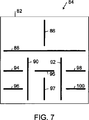
図7は、ユーザ指定レイアウト80から導出可能な相対レイアウト仕様84の一例を示している。相対レイアウト仕様84は、グラフィックスオブジェクトA〜Kのうちの隣り合うもの同士の間に、パーティション86〜100(ディビジョンとも呼ばれる)を示している。パーティション86〜100は、ページ82を複数のセルに分割し、各セルは、グラフィックスオブジェクトA〜Kのうちのちょうど一つを含む。
FIG. 7 shows an example of a
図8は、相対レイアウト仕様84(図7参照)に従ってページレイアウト発生器モジュール64により決定されたグラフィックスオブジェクトA〜Kの最終レイアウト102の一例を示している。図7に示した最終レイアウト102は、レンガスタイルレイアウトに対応し、当該レイアウトにおいて、ページ82上のグラフィックスオブジェクトA〜Kの相対面積は、ページ82の端と、グラフィックスオブジェクトA〜Kとの間における指定されたマージン空間、及びグラフィックスオブジェクトのうちの隣り合うもの同士の間における指定されたガッター余白部を除いて、画像間に空きスペースが全く生じないように選択される。
FIG. 8 shows an example of the
III.相対位置に基く制御によるページ上のグラフィックスオブジェクトの配置
A.はじめに
ページレイアウト発生器モジュール64は、各ページレイアウトにおけるグラフィックスオブジェクトの相対位置、又は面積についての明確な好みによって管理され、又は制御されることができる。この機能によれば、ユーザは、グラフィックスオブジェクトの相対位置についての好みを入力することができ、それによってページレイアウト発生器モジュール64に、ユーザのグラフィックスオブジェクト配置の一般的好みに合致するグラフィックスオブジェクトの特定のレイアウトを生成させ、同時に、より専門的に、かつより美術的に美しい形でクリーナを表示させることができる。
III. Placement of graphics objects on the page with control based on relative position
A. First, the page
以下で詳細に説明するように、ページレイアウト発生器モジュール64は、グラフィックスオブジェクトのユーザ指定レイアウトを受け取り、ユーザ指定レイアウトから相対レイアウト仕様を導出し、相対レイアウト仕様に従ってグラフィックスオブジェクトの最終レイアウトを決定する。
As described in detail below, the page
B.グラフィックスオブジェクトのユーザ指定レイアウトの受け取り
一般に、ページレイアウト発生器モジュール64は、グラフィックスオブジェクトのユーザ指定レイアウトを、種々の方法で受け取ることが出来る。例えばユーザは、グラフィックベースのレイアウトツールを使用して、グラフィックスオブジェクトレイアウトを生成する場合がある。あるいはユーザは、グラフィックスオブジェクトレイアウトの手書きモックアップ(すなわち、概略図、又はラフスケッチ)の画像、並びにその手書きモックアップ上の種々のグラフィックス要素をページ上にレイアウトされるグラフィックスオブジェクトの対応するデジタルファイルにリンクするマッピング(例えば、インデックス、その他の参照情報)を入力する場合がある。
B. Receiving a User-Specified Layout of a Graphics Object In general, the page
1.グラフィックスオブジェクトのユーザ指定レイアウトを作成するためのグラフィカルユーザインタフェース
図9は、ユーザが、選択されたグラフィックスオブジェクトの表現をページ上に配置するためのコマンドを入力することによりユーザ指定レイアウトを作成するための、ユーザインタフェース110の一実施形態を示している。グラフィカルユーザインタフェース110は一般に、レイアウトツールによって生成され、レイアウトツールは、ユーザがページ上のグラフィックス要素のサイズ、及び位置を調節出来るようにするための種々のグラフィックスベースの機能(例えば、Microsoft(R)のPowerPoint(R)、及びMicrosoft(R)のVisio(R)のようなソフトウェアアプリケーションプログラムによって一般に提供される機能)を備えたソフトウェアアプリーケーションプログラムによって実施される。
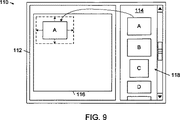
1. FIG. 9 is a graphical user interface for creating a user-specified layout of a graphics object . FIG. 9 shows the creation of a user-specified layout by a user entering a command for placing a representation of a selected graphics object on a page. FIG. 3 illustrates one embodiment of a
ユーザインタフェース110は、レイアウトウィンドウ112、及びグラフィックスオブジェクトブラウジングウィンドウ114を含む。レイアウトウィンドウ112はページ116を表示し、その上にユーザは、ユーザ指定グラフィックスオブジェクトレイアウトを作成することができる。グラフィックスオブジェクトブラウジングウィンドウ114は、ページ116上にレイアウトすることが可能なグラフィックスオブジェクトの解像度を下げたものからなる一列のサムネイル118を含む。各グラフィックスオブジェクトサムネイル118は、そのグラフィックスオブジェクトサムネイルにより表現されるグラフィックスオブジェクトに対応するファイルに(例えばポインタ、その他の参照情報、又はインデックスによって)リンクされる。
The
ユーザは、グラフィックスオブジェクトブラウジングウィンドウ114から、幾つかのグラフィックスオブジェクトサムネイル118を、レイアウトウィンドウ112にあるページ116上の所望の位置へドラッグすることができる。図9に示すように、ユーザは、グラフィックスオブジェクトサムネイルAをグラフィックスオブジェクトブラウジングウィンドウ114からページ116の左上角の位置へドラッグする場合がある。グラフィックスオブジェクトサムネイルをページ116上に位置決めした後、ユーザは、グラフィックスオブジェクトサムネイルの縁上の一点、又は角の一点を選択し、選択した点をページ116上の所望の位置まで動かすことにより、グラフィックスオブジェクトサムネイルをリサイズすることができる。例えば、ユーザは、図9に破線矢印で概略的に示されているように、グラフィックスオブジェクトサムネイルAの4つの縁をそれぞれ外向きの方向へドラッグすることにより、グラフィックスオブジェクトサムネイルAのサイズを拡大することができる。図10は、ユーザが、グラフィックスオブジェクトサムネイルDをページ116の左端に接する位置までドラッグし、グラフィックスオブジェクトサムネイルDのサイズを破線矩形で示すサイズまで縮小した後に生成されるレイアウトを示している。
The user can drag several graphics object
ユーザがユーザ指定グラフィックスオブジェクトレイアウトを作成する際に、レイアウトツールは、ページ116上の種々のグラフィックスオブジェクトの位置、及びサイズを記録する間取り仕様を管理する。一部の実施形態において、間取り仕様は、ページ116上にレイアウトされるグラフィックスオブジェクトサムネイルのバウンディングボックスの左上角、及び右下角のページ座標を記録する場合がある。さらに、間取り仕様は、バウンディングボックスと、当該バウンディングボックスにより表現されるグラフィックスオブジェクトサムネイルにリンクされたグラフィックスオブジェクトファイルのうちの対応するものとの間のマッピングを記録する場合がある。以下で詳しく説明するように、ページレイアウト発生器モジュール64は、間取り仕様から相対レイアウト仕様を生成する。
As the user creates a user-specified graphics object layout, the layout tool manages a floor plan specification that records the location and size of various graphics objects on the
2.グラフィックスオブジェクトのユーザ指定レイアウトの画像の受け取り
図11は、グラフィックスオブジェクト配置システム60(図4参照)の一実施形態120を示している。システム120は、ページ上のグラフィックスオブジェクトのユーザ指定レイアウトの画像126から間取り仕様128を生成する画像分析モジュール124を含む、ページレイアウト発生器モジュール64の一実施形態122を含む。このプロセスにおいて、画像分析モジュール124は、画像126におけるグラフィックスオブジェクトの位置、及びサイズを決定し、その情報を間取り仕様128として記録する。ユーザ指定レイアウトの画像126は通常、用紙上に生成され、デジタルスキャンにより画像ファイルに変換されたグラフィックスオブジェクトレイアウトの手書きスケッチに対応し、又はタッチスクリーンディスプレイ、若しくはグラフィックスタブレットのようなタッチパッド上に生成されるグラフィックスオブジェクトレイアウトの手書きスケッチに対応する。
2. Receiving an Image of a User-Specified Layout of a Graphics Object FIG. 11 illustrates one embodiment 120 of the graphics object placement system 60 (see FIG. 4). The system 120 includes an
実施形態によっては、間取り仕様は、画像126上にレイアウトされたグラフィックスオブジェクトのバウンディングボックスの左上角、及び右下角のページ座標を記憶する場合がある。さらに、間取り仕様は、バウンディングボックスの座標と、画像126上のグラフィックスオブジェクトにリンクされ、データベース130に記憶されたグラフィックスオブジェクトファイルのうちの対応するものとの間のマッピングを記録する場合がある。
In some embodiments, the floor plan specification may store the page coordinates of the upper left corner and lower right corner of the bounding box of a graphics object laid out on the
実施形態によっては、画像分析モジュール124は、画像126からグラフィックスオブジェクト識別子を抽出し、(例えば、抽出された識別子をデータベース130内の索引として使用することにより、)抽出された識別子により示されるグラフィックスオブジェクトファイルを求めることにより、そのマッピングを決定する場合がある。他の実施形態において、ユーザは、画像126上の種々のグラフィックスオブジェクトと、データベース130に記憶された画像ファイルのうちの対応するものとの間のマッピングを、グラフィカルユーザインタフェースを介して入力する場合がある。
In some embodiments, the
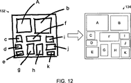
図12は、グラフィックスオブジェクトのユーザ指定レイアウト132の画像の一例、及び画像分析モジュール124によってユーザ指定レイアウト132から導出された間取り仕様のグラフィック表現134の一例を示している。ユーザ指定レイアウト132上の各グラフィックスオブジェクトには、それぞれ識別子(すなわち、A〜K)が付されている。画像分析モジュール124は、それらの識別子を抽出し、ユーザ指定レイアウト132上の種々のグラフィックスオブジェクトと、データベース130内のグラフィックスオブジェクトファイルのうちの対応するものとの間の対応関係を判断する。以下で詳細に説明するように、ページレイアウト発生器モジュール64は、間取り仕様から相対レイアウト仕様を生成する。
FIG. 12 shows an example of an image of a user-specified
3.グラフィックスオブジェクトのユーザ指定レイアウトに対する条件の付加
実施形態によっては、ページレイアウト発生器モジュール64は、ユーザ指定レイアウトから相対レイアウト仕様を導出するページレイアウト発生器モジュール64の能力を向上させるために、ユーザ指定グラフィックスオブジェクトレイアウトに対し、特定の条件を課す場合がある。例えば、以下で説明する一部の実施形態において、ページレイアウト発生器モジュール64は、ユーザ指定レイアウトにおける水平投影、及び垂直投影に基いて、相対レイアウト仕様を解明する場合がある。そのような実施形態では、場合によっては、ページレイアウト発生器モジュール64は、ユーザ指定グラフィックスオブジェクトレイアウトに対し、下記の条件を課す場合がある。
・ユーザ指定レイアウトにおいて、各グラフィックス要素は、完全にページ内になければならない。
・ユーザ指定レイアウトにおいて、各グラフィックス要素は、ページ上の他のいずれのグラフィックス要素とも重なってはならない。
・ユーザ指定レイアウトにおいて、グラフィックス要素は、ページの一連の領域ニ分割によって生成されるパーティションによってグラフィックス要素を互いに分離することが可能な形で配置されなければならない。ただし、各分割は、ページ116の矩形領域を2つのより小さな矩形領域に分割する水平分割、又は垂直分割であるものとする。
3. Adding conditions to a user-specified layout of a graphics object In some embodiments, the page
• In a user-specified layout, each graphics element must be completely within the page.
• In a user specified layout, each graphics element must not overlap any other graphics element on the page.
In a user-specified layout, the graphics elements must be arranged in such a way that the graphics elements can be separated from each other by partitions generated by a series of area divisions of the page. However, each division is assumed to be horizontal division or vertical division in which the rectangular area of the
実施形態によっては、ユーザ指定グラフィックスオブジェクトレイアウトが上記要件の一つに違反するという判定結果に応答し、システム60は、そのユーザ指定グラフィックスオブジェクトレイアウトを修正しなければならないことをユーザに知らせるエラーメッセージを発行する場合がある。
In some embodiments, in response to a determination that a user specified graphics object layout violates one of the above requirements, the
C.ユーザ指定レイアウトからの相対レイアウト仕様の導出
ページレイアウト発生器モジュール64は、非常に様々な方法で、ユーザ指定レイアウトから相対レイアウト仕様を導出することができる。このプロセスにおいて、ページレイアウト発生器モジュール64は、ユーザ指定レイアウトから、グラフィックスオブジェクトの相互間における、又は共通の基準点(例えば、ページの角のポイント、又は端のポイント)に対するグラフィックスオブジェクトの相対位置の表現を導出する。相対レイアウト仕様は通常、各セルが、ユーザ指定レイアウトにおいて指定されたちょうど一つのグラフィックスオブジェクトを含むものになるような、ページのセルへの分解を表す。実施形態によっては、間取りモデルは、2進空間分割モデルのような再帰分割(又は、分割)モデルに対応する場合があり、2進空間分割モデルは、ツリー構造として構成されることがある。
C. Deriving relative layout specifications from user-specified layouts The page
ページレイアウト発生器モジュール64は通常、ユーザ指定グラフィックスオブジェクトレイアウトの表現を記憶する間取り仕様から、相対レイアウト仕様を導出する。実施形態によっては、間取り仕様は、ユーザが、グラフィックスオブジェクト62のそれぞれについて指定したページの種々の矩形領域の左上角、及び右下角のページ座標を含む場合がある。ページレイアウト発生器モジュール64は、矩形領域の位置を分析することにより、種々の矩形領域との間に一対一の関係を有する一組のセルを生成することが可能な、ページの一連のパーティション(又は、ディビジョン)を特定する。これらのパーティションは通常、一連のパーティションを記録する階層ツリー構造として編成され、当該一連のパーティションから、矩形領域に対応する一組のセルを決定することができる。実施形態によっては、ページレイアウト発生器モジュール64は、相対レイアウト仕様をそれぞれ個別の二分木データ構造に記憶する場合があり、二分木データ構造は、グラフィックスオブジェクトに対応するリーフノード、及び対応するページのパーティションに対応する内部ノードを有する。
The page
実施形態によっては、ページレイアウト発生器モジュール64は、ユーザ指定レイアウトの水平ヒストグラムプロファイル、及び垂直ヒストグラムプロファイルを求め、グラフィックスオブジェクトを相互に分離するパーティションを求めることにより、ユーザ指定レイアウトからグラフィックスオブジェクトの相対レイアウトを解明する場合がある。
In some embodiments, the page
一例として、図13Aは、ページ142上のグラフィックスオブジェクト(すなわち、グラフィックスオブジェクトL、M、N、O)のユーザ指定レイアウト140の一例を示している。図13はさらに、水平ヒストグラムプロファイル144、及び垂直ヒストグラムプロファイル146も示している。水平ヒストグラムプロファイル144は、グラフィックスオブジェクトL〜Oのカウント数の垂直投影から、水平軸(x)に沿った位置の関数として計算される。垂直ヒストグラムプロファイル144は、グラフィックスオブジェクトL〜Oのカウント数の水平投影から、垂直軸(y)に沿った位置の関数として計算される。これらの実施形態によれば、ページレイアウト発生器モジュール64は、水平ヒストグラム144、及び垂直ヒストグラム146における極小値に基いて、ページ142を分割するパーティションを決定する。
As an example, FIG. 13A shows an example of a user specified
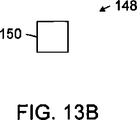
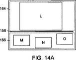
一実施形態において、ページレイアウト発生器モジュール64は、まず、図13A、及び図13Bに示すように、ページ142の全体を含むバウンディングボックス152に関連する1つのノード150を有する初期ツリー148を生成する。ページレイアウト発生器モジュール64は、ヒストグラム144におけるゼロ値を識別し、識別されたゼロ値のうちの1つを選択し、選択されたゼロ値の位置にあるパーティションを使用して、現在ノード150を2つのノードに分割する。図13Aに示す例において、ヒストグラム144、146には、単一のゼロ値154しか存在しない。ページレイアウト発生器モジュール64は、ゼロ値154の位置に水平パーティションを生成する(図14A参照)。水平パーティション(H)は、ノード150を2つのノード158、160に分割し、ノード158、160は、図14A、及び図14Bに示すようにンディングボックス166、164に関連する。
In one embodiment, the page
もし、あるノードがグラフィックスオブジェクトを1つしか有しないバウンディングボックスに関連する場合、そのノードは、それ以上分割されない。例えば、図14A、及び図14Bに示す分割プロセスの段階において、ノード158は、バウンディングボックス164に関連し、従って、それ以上分割されない。もし、あるノードが、2以上のグラフィックスオブジェクトを含むバウンディングボックスに関連する場合、そのノードは、現在ノードとして指定され、プロセスは繰り返される。図14A、及び図14Bに示す分割プロセスの段階において、ノード160は、バウンディングボックス166に関連し、バウンディングボックス166は、3つのグラフィックスオブジェクトM〜Oを含む。従って、この段階の結果、ノード160には、現在ノードのラベルが付され、プロセスは繰り返される。
If a node is associated with a bounding box that has only one graphics object, that node is not further divided. For example, at the stage of the splitting process shown in FIGS. 14A and 14B,
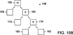
ノード160について分割プロセスを繰り返すプロセスの一例として、ページレイアウト発生器モジュール64は、現在ノード160に関連するバウンディングボックス166におけるグラフィックスオブジェクトの水平ヒストグラム、及び垂直ヒストグラムを求める場合がある。ページレイアウト発生器モジュール64は、水平ヒストグラムにおける2つのゼロのうちの最初のものを選択し、現在ノード160を2つのノード172、174に分割する垂直パーティション170を使用して、現在ノード160を分割する(図15A参照)。その後、ページレイアウト発生器モジュール64は、グラフィックスオブジェクトN、及びOを含み、かつ現在ノード174に関連するバウンディングボックスにおけるグラフィックスオブジェクトの水平ヒストグラム、及び垂直ヒストグラムを求める(図15B参照)。ページレイアウト発生器モジュール64は、水平ヒストグラムにおけるゼロのみを選択し、現在ノード174を2つのノード180、182に分割する垂直パーティションを使用して、現在ノード174を分割する(図15B参照)。図15Bに示すツリー構造の例において、内部ノード150、160、174は、パーティション156、170、178にそれぞれ対応するのに対し、リーフノード158、172、180、182は、グラフィックスオブジェクトL、M、N、Oにそれぞれ対応する。
As an example of a process that repeats the splitting process for
D.相対レイアウト仕様に基づくグラフィックスオブジェクトの最終レイアウトの決定
1.概要
ページレイアウト発生器モジュール64は、相対レイアウト仕様から、ページ上のグラフィックスオブジェクトの最終配置を決定、又は生成する。上で説明したように、相対レイアウト仕様は、非常に様々な間取りモデルのうちの任意の1つを反映するデータ構造に対応する場合がある。下記の実施形態は、2進空間分割モデルに対応する相対レイアウト仕様を例として説明され、当該モデルに従って、グラフィックスオブジェクトの相対位置が、二分木構造に記録される。
D. Determining the final layout of a graphics object based on relative layout specifications
1. The summary page
2.ページ上のグラフィックスオブジェクトの最終配置の生成
実施形態によっては、ページレイアウト発生器モジュール64は、ページ上の種々のグラフィックスオブジェクトの相対位置を表す個別のツリー構造を受け取る場合がある。ツリー構造の各リーフノードは、アスペクト比値(a)を有し、厳密面積スタイルレイアウトの場合、さらに公称サイズ値(e)を有する。ツリー構造の各内部ノードは、ページ上での水平分割と垂直分割のいずれかを示す。ページレイアウト発生器モジュール64は、各ページ上の種々のグラフィックスオブジェクトの面積を求め、その後、ページ空間の正確な領域をツリー構造の各ノードに割当てる。ページの割当て済み領域は、対応するツリー構造と同様に入れ子構造を成す。本明細書において、この割当て済み領域は、「セル」と呼ばれる。実施形態によっては、セルが分かった後、そのセルに割当てられるグラフィックスオブジェクトの位置は、そのグラフィックスオブジェクトをセル内の中央に位置決めすることによって決定される場合がある。
2. In some embodiments of generating final placement of graphics objects on the page , the page
a.グラフィックスオブジェクトの面積の決定
グラフィックスオブジェクトの面積は、所望の精度、所望のレイアウトスタイル、及び利用可能な計算リソースに応じて、バウンディングボックスに基く面積決定法、パスに基く面積決定法、又は線形システムに基く面積決定法によって決定される。
a. Determining the area of a graphics object The area of a graphics object can be determined based on a bounding box, area based on a path, or linear, depending on the desired accuracy, desired layout style, and available computational resources. It is determined by an area determination method based on the system.
i.バウンディングボックスに基くグラフィックスオブジェクト面積の決定
例示的実施形態として、バウンディングボックス決定プロセスの目的は、所与のツリー構造における各内部ノードについて、アスペクト比値、及び公称サイズ値を計算することである。各バウンディングボックスは、そのバウンディングボックスに包含されるボックスによって決定される。
i. Determination of Graphics Object Area Based on Bounding Box As an exemplary embodiment, the purpose of the bounding box determination process is to calculate an aspect ratio value and a nominal size value for each internal node in a given tree structure. Each bounding box is determined by the boxes contained in that bounding box.
後で詳しく説明するように、バウンディングボックスは、グラフィックスオブジェクトのアスペクト比、及び公称サイズを使用して計算される。厳密面積スタイルレイアウトの場合、各グラフィックスオブジェクトの公称サイズは、間取り仕様上の対応する矩形の面積に等しくなるようにセットされる場合がある。実施形態によっては、バウンディングボックス特性評価プロセスは、リーフノードから開始され、図16に示すように深さ優先順で、ルートノードへ向けて実行される場合がある。 As described in detail later, the bounding box is calculated using the aspect ratio of the graphics object and the nominal size. For a strict area style layout, the nominal size of each graphics object may be set to be equal to the area of the corresponding rectangle on the floor plan specification. In some embodiments, the bounding box characterization process starts at the leaf node and may be performed toward the root node in depth-first order as shown in FIG.
任意の内部ノードのアスペクト比、及び公称サイズを求める式は、下記のとおりである。一般に、アスペクト比a、及び公称サイズeを有する任意の画像バウンディングボックスの場合、

ただし、
式(1)におけるアスペクト比は、大きい方の公称高さを2つの公称幅の合計で割った比であり、式(2)における公称サイズは、大きい方の公称高さと、2つの公称幅の合計との積である。式(3)における最大値を見付けることにより、2つの子ノードボックスのうちのいずれが名目上高く、従って、親ノードボックスの高さを支配するのかを判断することができる。 The aspect ratio in equation (1) is the ratio of the larger nominal height divided by the sum of the two nominal widths, and the nominal size in equation (2) is the larger nominal height and the two nominal widths. It is the product of the sum. By finding the maximum value in equation (3), it can be determined which of the two child node boxes is nominally higher and therefore dominates the height of the parent node box.
もし、2つの子ノードが、順に重ねて配置されたボックスを表す場合、それらを包含するバウンディングボックスのアスペクト比、及び公称サイズは、下記のようになる。 If two child nodes represent boxes placed one on top of the other, the aspect ratio and nominal size of the bounding boxes that contain them are as follows:
ただし、
この場合、式(6)から、2つの子ノードボックスのうちのいずれの幅が名目上広く、従って親ノードボックスの幅を支配するのかを判断することができる。 In this case, it can be determined from equation (6) which of the two child node boxes is nominally wide and therefore dominates the width of the parent node box.
ルートノードのバウンディングボックスは、対応するツリー構造により指定されるページのレイアウト全体の形、及び公称サイズを有する。本明細書において、ルートノードのバウンディングボックスは、「主バウンディングボックス」と呼ばれる。 The bounding box of the root node has the overall layout and nominal size of the page specified by the corresponding tree structure. In this specification, the bounding box of the root node is referred to as a “main bounding box”.
主バウンディングボックスのアスペクト比、及び公称サイズが分かっている場合、グラフィックスオブジェクトiについてのバウンディングボックスに基づく面積Aiは、下記のように計算される。 If the aspect ratio of the main bounding box and the nominal size are known, the bounding box-based area A i for graphics object i is calculated as follows:
ただし、ei、及びepbbは、グラフィックスオブジェクトi、及び主バウンディングボックスのそれぞれの公称サイズであり、Apbbは、下記のように計算される主バウンディングボックスの面積である。 Here, e i and e pbb are the nominal sizes of the graphics object i and the main bounding box, respectively, and A pbb is the area of the main bounding box calculated as follows.
ただし、Apageは、使用可能なページ空間の面積である。 Here, A page is an area of usable page space.
図16は、再帰プロセスの一実施形態を示すフロー図であり、ページレイアウト発生器モジュール64は、この再帰プロセスにより、ツリー構造の種々のノードについて、バウンディングボックスの相対的な高さ寸法、及び幅寸法を計算する。
FIG. 16 is a flow diagram illustrating one embodiment of a recursive process in which the page
このプロセスは、現在ノードとしてのルートノードから開始される。現在ノードが終端ノードであるか否かを判断する(図16、ブロック480)。もし現在ノードが終端ノードであった場合、関連グラフィックスオブジェクトの公称高さ、及び公称幅を有するバウンディングボックスを決定する(図16、ブロック482)。もし現在ノードが終端ノードではなかった場合、現在ノードの2つの子ノード(すなわち、左側子ノード、及び右側子ノード)を同じ再帰プロセスに提出する(図16、ブロック484、486)。現在ノードについてのバウンディングボックスを形成するために、下記のように、2つの子ノードのバウンディングボックスを結合する。ページレイアウト発生器モジュール64は、現在ノードが水平分割であるか、それとも垂直分割であるかを判断する(図16、ブロック488)。もし現在ノードが水平分割を表している場合、バウンディングボックスの公称幅は、2つの子ノードのバウンディングボックスのうちの幅の広い方の公称幅にセットされ(図16、ブロック490)、バウンディングボックスの公称高さは、2つの子ノードのバウンディングボックスの公称高さの合計にセットされる。もし現在ノードが垂直分割を表している場合、(図16、ブロック488)、バウンディングボックスの公称高さは、2つの子ノードのバウンディングボックスのうちの高い方の公称高さにセットされ(図16、ブロック494)、バウンディングボックスの公称幅は、2つの子ノードのバウンディングボックスの公称幅の合計にセットされる。このプロセスは、ルートノードについてのバウンディングボックスの計算が完了するまで続けられる。
This process starts from the root node as the current node. It is determined whether the current node is a terminal node (FIG. 16, block 480). If the current node is a terminal node, a bounding box having the nominal height and nominal width of the associated graphics object is determined (FIG. 16, block 482). If the current node is not a terminal node, submit the two child nodes of the current node (ie, the left child node and the right child node) to the same recursive process (FIG. 16, blocks 484, 486). To form the bounding box for the current node, combine the bounding boxes of the two child nodes as follows: The page
ii.パスに基くグラフィックスオブジェクト面積の決定
パスに基く面積決定法によれば、ページレイアウト発生器モジュール64は、2007年6月27日に出願された米国特許出願第11/769,671号の図9〜図10J、及び図24のブロック410に関係して以下に記載するパス生成プロセスに従って、ツリー構造を通るパスPiを生成する。
ii. According to the area determination method based on the decision path of the graphics object area based on the path, the page
ページレイアウト発生器モジュール64は、各パスPiについてパス長さL(Pi)を計算する。もしパスPiが垂直であった場合、その長さは、下記のようになる。
The page
グラフィックスオブジェクトの高さ(HGO)は、下記のように書き表すことができる。 The height (H GO ) of the graphics object can be expressed as follows:
ただし、Aは、グラフィックスオブジェクトの面積であり、aは、高さを幅で割った比として定義されるアスペクト比であり、Qは、面積の平方根である。従って、もしPiが垂直パスであれば、その長さは下記のように書き表すことができる。 Where A is the area of the graphics object, a is the aspect ratio defined as the ratio of height divided by width, and Q is the square root of the area. Therefore, if Pi is a vertical path, its length can be written as:
ただし、Kiは、式(9)における最初の2つの項(すなわち、パスPiに沿った全ての固定距離)の合計であり、Qi,jは、パスPi上の第jの可変面積オブジェクトの面積の平方根であり、ai,jは、パスPi上の第jの可変面積オブジェクトのアスペクト比である。なお、加算項は、パスPi上の可変面積グラフィックスオブジェクトの高さの合計に対応する。 Where K i is the sum of the first two terms in equation (9) (ie, all fixed distances along path P i ), and Q i, j is the jth variable on path P i. Is the square root of the area of the area object, and a i, j is the aspect ratio of the jth variable area object on the path P i . Incidentally, addition term corresponds to the sum of the heights of variable area graphic objects on path P i.
同様の計算により、水平パスPiの長さは、下記のように書き表すことができる。 By the same calculation, the length of the horizontal path P i can be written as follows.
ただし、Kiは、パスPiに沿った固定面積グラフィックスオブジェクトの水平固定距離、及び幅の合計である。厳密面積スタイルレイアウトの場合、各可変面積グラフィックスアセンブリには、公称サイズが割当てられ、公称サイズは変数eで表される。マルチ要素グラフィックスオブジェクトの場合、当該オブジェクトは、構成要素として2以上の単一要素グラフィックスオブジェクト(例えば、ビデオからの一連のキーフレームなど)を含み、単一の集合体公称サイズが、グラフィックスオブジェクト全体に割当てられ、マルチ要素グラフィックスオブジェクト内の個々のグラフィックスオブジェクトの公称サイズは、その集合体公称サイズをそのグラフィックスオブジェクト内のグラフィックスオブジェクトの数で割ったサイズに等しくなるようにセットされる。このセクションの残りの部分では、パスPi上の各グラフィックスオブジェクトjが、正の公称サイズejを有する単一要素グラフィックスオブジェクトであるものと仮定する。公称サイズは実際の面積に比例するので、上で定義された変数Qは、(絶対面積ではなく)公称サイズの平方根を反映するように、下記のように一般化することができる。 K i is the total of the horizontal fixed distance and the width of the fixed area graphics object along the path P i . For a strict area style layout, each variable area graphics assembly is assigned a nominal size, which is represented by the variable e. In the case of a multi-element graphics object, the object includes two or more single-element graphics objects (eg, a series of key frames from a video) as components, and a single aggregate nominal size Assigned to the entire object, the nominal size of an individual graphics object in a multi-element graphics object is set equal to the aggregate nominal size divided by the number of graphics objects in that graphics object Is done. The remainder of this section, each graphic object j on a path P i is assumed that the single element graphic object that has a positive nominal size e j. Since the nominal size is proportional to the actual area, the variable Q defined above can be generalized to reflect the square root of the nominal size (not the absolute area) as follows:
ただし、gは、g2に公称サイズを乗じたものが、絶対測定可能面積(例えば、平方インチ)になるような、正のスカラー値である。Qを
ただし、ei,jは、パスPi上の第jの可変面積グラフィックスオブジェクトの公称サイズである。 Where e i, j is the nominal size of the jth variable area graphics object on path P i .
もしPiが垂直パスであり、ページ上の使用可能エリアの高さがHPAGEである場合、下記の式をgiについて解くことにより、使用可能エリアの高さが高い限り、Piが正確であるときの値が得られる。 If P i is a vertical path and the height of the usable area on the page is H PAGE , then P i is accurate as long as the height of the usable area is high by solving the following equation for g i A value is obtained when.
同様に、もしPiが水平パスであり、使用可能エリアの幅がWPAGEである場合、下記の式をgiについて解くことにより、そのパスが、使用可能エリアの幅全体にわたってちょうど適合するときの値が得られる。 Similarly, if P i is a horizontal path and the width of the usable area is W PAGE , when the path just fits across the entire width of the usable area by solving the following equation for g i The value of is obtained.
ツリー構造により実施される各水平パスについて、WPAGE>Kiであるものと仮定し、さらに、ツリー構造により実施される各垂直パスについて、HPAGE>Kiであるものと仮定する。これは、各パスに沿った固定距離がそれぞれの寸法内に適合することを意味し、従って、ツリー構造によって表されるレイアウトは「実現可能」であり、全てのグラフィックスオブジェクトがページ上に収まるような、可変面積グラフィックスオブジェクトの面積について正の値が存在することを意味する。 Assume that W PAGE > K i for each horizontal path implemented by the tree structure, and further assume that H PAGE > K i for each vertical path implemented by the tree structure. This means that a fixed distance along each path fits within each dimension, so the layout represented by the tree structure is “realizable” and all graphics objects fit on the page. This means that there is a positive value for the area of the variable area graphics object.
一実施形態において、可変面積グラフィックスオブジェクトの面積は、可能な限り広く作成されるが、それでも、Piが垂直パスであるか、それとも水平パスであるかに応じて式(16)又は式(17)を使用し、(各パスPiについて)giについて解くことにより、全てのグラフィックスオブジェクトをページの使用可能エリアに完全に収めることができる。上記のように、レイアウトが実現可能なものであることを前提としているので、giについての各解は正になる。もし、g*を全てのパスにわたる最小の解として下記のように定義した場合、
iii.線形システムに基くグラフィックスオブジェクト面積の決定
レンガスタイルレイアウトの場合、グラフィックス要素の面積は、まずQの値を計算することによって決定される。Qの値が分かった後、それらを二乗し、絶対測定可能面積(例えば、平方インチを単位として表される)を求める。Qの値は、次の2つの仮説に基いて計算される:(1)グラフィックス要素が占めるエリアの高さは、ページ上の使用可能エリアの高さに等しくなるように拘束される。(2)グラフィックス要素が占めるエリアの幅は、ページ上の使用可能エリアの幅に等しくなるよう拘束される。大抵の場合、仮説(I)と仮説(II)のいずれか一方のみが、実現可能な解を生成する。なぜなら、他方の仮説においては、他方の(拘束されていない)寸法が、使用可能空間より大きくなるからである。最終的な一組のグラフィックス要素エリアを生成するために、実現可能な解を生成する仮説が選択される。
iii. Determination of Graphics Object Area Based on Linear System In the case of a brick style layout, the area of a graphics element is first determined by calculating the value of Q. After the values of Q are known, they are squared to determine the absolute measurable area (eg expressed in square inches). The value of Q is calculated based on the following two hypotheses: (1) The height of the area occupied by the graphics element is constrained to be equal to the height of the available area on the page. (2) The width of the area occupied by the graphics element is constrained to be equal to the width of the usable area on the page. In most cases, only one of hypothesis (I) and hypothesis (II) will produce a feasible solution. This is because, in the other hypothesis, the other (unconstrained) dimension is larger than the usable space. In order to generate the final set of graphics element areas, hypotheses that produce feasible solutions are selected.
仮説(I)と仮説(II)のいずれにおいても、Qの値は、N個の未知数を有する線形システムの式の解として計算される。ただし、Nは、グラフィックス要素の数である。N−1個の式はそれぞれ、完全なツリー構造の内部ノードから得られる。なぜなら、N個のグラフィック要素を有するツリーには、ちょうど(N−1)個の内部ノードが存在するからである。 In both hypothesis (I) and hypothesis (II), the value of Q is calculated as the solution of a linear system equation with N unknowns. Here, N is the number of graphics elements. Each of the N-1 expressions is obtained from internal nodes of the complete tree structure. This is because there are exactly (N-1) internal nodes in a tree with N graphic elements.
垂直分割、又は領域切断を表す内部ノードの場合、対応する式は、まずその内部ノードの2つの子ノードのそれぞれから1つ、合わせて2つの垂直パスを得て、それらの長さを同じ長さにセットすることによって導出される。上記の式(11)を参照すると、左側子ノードからの垂直パスをPLで表し、右側子ノードからの垂直パスをPRで表した場合、対応する式は、下記のようになる。 For an internal node representing a vertical split, or region cut, the corresponding expression first gets two vertical paths, one from each of the two child nodes of that internal node, and their lengths are the same length It is derived by setting it. Referring to the above equation (11) represents the vertical path from the left child node P L, if the vertical path from the right child node represented by P R, the corresponding equation is as follows.
ただし、変数jは、PR上でグラフィックスオブジェクトを索引付けし、変数kは、PL上でグラフィックスオブジェクトを索引付けする。式(20)を変形すると、下記のようになる。 However, the variable j is, indexes the graphic objects on the P R, variable k, indexes the graphic objects on the P L. The equation (20) is transformed as follows.
この状況は、水平分割、又は領域切断を表す内部ノードの場合に似ている。2つの水平パスを得て、それらの長さを同じ長さにセットすると、下記の式が得られる。 This situation is similar to the case of internal nodes representing horizontal splits or area cuts. If we get two horizontal passes and set their lengths to the same length, we get:
各内部ノードについて式(20)又は(22)の形の式を作成することにより、N個の未知数について、N−1個の式が得られる。 By creating an expression of the form (20) or (22) for each internal node, N-1 expressions are obtained for N unknowns.
仮説Iの場合、第Nの式は、ルートノードからの任意の垂直パスの長さを、使用可能エリアの高さに等しくなるようにセットすることによって得られる。仮説IIの場合、第Nの式は、ルートノードからの任意の水平パスの長さを、使用可能エリアの幅に等しくなるようにセットすることによって得られる。 For Hypothesis I, the Nth equation is obtained by setting the length of any vertical path from the root node to be equal to the height of the usable area. For Hypothesis II, the Nth equation is obtained by setting the length of any horizontal path from the root node to be equal to the width of the available area.
仮説Iと仮説IIのいずれの場合も、N個の式は、行列ベクトル(Ax=b)の形で書かれる。行列は、ゼロ、グラフィックス要素アスペクト比の正、及び負の平方根、並びにグラフィックス要素アスペクト比の平方根の正の逆数、及び負の逆数のみを含む。ベクトルxのN個の要素は、Q個の変数である。ベクトルbのN個の要素のうち、(N−1)個は、式(20)、又は式(21)の右辺に従って計算され、残りは、使用可能エリアの高さ(仮説I)、又は幅(仮説II)(から対応する行を得るために使用されるパスに沿った固定距離を差し引いたもの)に等しくなる。逆行列(A)*bを計算することにより、Q値のベクトルが得られる。 In both hypothesis I and hypothesis II, the N equations are written in the form of a matrix vector (Ax = b). The matrix includes only zeros, positive and negative square roots of graphics element aspect ratios, and positive and negative reciprocals of square roots of graphics element aspect ratios. The N elements of the vector x are Q variables. Of the N elements of the vector b, (N−1) elements are calculated according to the right side of Expression (20) or Expression (21), and the rest is the height (hypothesis I) or width of the usable area. (Hypothesis II) equal to (subtract the fixed distance along the path used to obtain the corresponding row). A vector of Q values can be obtained by calculating the inverse matrix (A) * b.
b.ツリー構造におけるノードの周りのバウンディングボックスの決定
絶対面積を計算した後、ツリー構造における各ノードの周りにバウンディングボックスを描画する。このプロセスを達成するために必要な実際のステップは、2点を除き、図16に示したようなバウンディングボックスに基く面積決定に関係して上で説明したバウンディングボックスを計算するためのプロセスと全く同様である。第1に、公称サイズは偶然に、実際のグラフィックスオブジェクト面積と等しくなることがある。第2に、内部ノードに割当てられる間隔は、無視されるのではなく、代わりにブロック492、及び496の計算において合計に加算される。
b. Determination of bounding box around nodes in tree structure After calculating the absolute area, a bounding box is drawn around each node in the tree structure. The actual steps necessary to achieve this process are the same as the process for calculating the bounding box described above in relation to the bounding box based area determination as shown in FIG. It is the same. First, the nominal size can happen to be equal to the actual graphics object area. Second, the interval assigned to the internal node is not ignored, but instead is added to the sum in the calculations of
c.ページ空間のグラフィックスオブジェクトへの割当てc. Assigning page space to graphics objects
i.ページ空間割当てプロセスの概要
実施形態によっては、ページ上の空白領域をノードに割当てるプロセスは、ページを複数のセルに分割し、各グラフィックスオブジェクトをそれぞれのセルの中に位置決めすることを含む場合がある。ページのセルへの分割は、まずページの使用可能エリア全体を第1の矩形とし、ページを複数の矩形に分割することにより開始される。各分割は、ルートノードから開始し、横型探索の順序で各内部ノードについて1本のラインセグメントを描くことにより達成される。
i. Overview of Page Space Allocation Process In some embodiments, the process of allocating blank areas on a page to nodes may include dividing the page into multiple cells and positioning each graphics object within each cell. is there. The division of a page into cells is started by first dividing the entire usable area of the page into a first rectangle and dividing the page into a plurality of rectangles. Each split is accomplished by drawing one line segment for each internal node starting from the root node and in the horizontal search order.
垂直分割に対応する内部ノードの場合、ページレイアウト発生器モジュール64は、使用可能領域の幅に沿って水平位置xを選択する。これを式で表すと例えば、x∈(0,1)のようになる。ただしx=0は、使用可能領域における最も左側の位置を表し、x=1は、使用可能領域における最も右側の位置を表す。この場合、下記のようになる。
For internal nodes corresponding to vertical splits, the page
ただし、al、el、及びar、erは、内部ノードの左側子ノード、及び右側子ノードについてのバウンディングボックスのアスペクト比、及び面積である。この式は、幅を比率として直接使用する。水平分割の場合の同様の式は、高さを使用する。すなわち、もしy=0が最下位置を表し、y=1が最上位置を表すものとし、使用可能空間の高さ方向における垂直位置をy∈(0,1)で表した場合、下記のようになる。 However, a l, e l, and a r, e r is the left child node of the internal node, and the aspect ratio of the bounding box for the right child node, and an area. This formula uses width directly as a ratio. A similar formula for horizontal split uses height. That is, if y = 0 represents the lowest position, y = 1 represents the highest position, and the vertical position in the height direction of the usable space is represented by y∈ (0, 1), become.
ただし、ab、eb、及びat、etは、内部ノードの最下部、及び最上部の子ノードについてのバウンディングボックスのアスペクト比、及び面積である。 However, a b, e b, and a t, e t is the bottom, and the aspect ratio of the bounding box of the children nodes of the top of the internal node, and an area.
ii.ページ空間をグラフィックスオブジェクトに割当てるプロセスの詳細
図17は、ページ上の空きの物理領域を現在のツリー構造のルートノードに割当てる方法の一実施形態を示している。この方法に従って、レイアウトスタイルは決定される(図17、ブロック630)。厳密面積スタイルレイアウトの場合、ページの使用可能エリア全体をルートノードに割当てる(図17、ブロック632)。レンガスタイルレイアウトの場合、ルートノードに割当てられるページ空間は、ルートノードに関連するバウンディングボックスの高さ、及び幅を有する(図17、ブロック634、636)。次に、ルートノードに割当てられた領域を、使用可能なページ空間の中央に位置決めする(図17、ブロック638)。
ii. Details of the process of allocating page space to graphics objects FIG. 17 illustrates one embodiment of a method for allocating free physical space on a page to the root node of the current tree structure. According to this method, the layout style is determined (FIG. 17, block 630). For a strict area style layout, the entire usable area of the page is assigned to the root node (FIG. 17, block 632). For a brick style layout, the page space allocated to the root node has the bounding box height and width associated with the root node (FIG. 17, blocks 634, 636). Next, the area allocated to the root node is positioned in the middle of the available page space (FIG. 17, block 638).
図18は、空きページ領域をツリー構造のあるノードの子ノードに割当てる方法の一実施形態を示している。このプロセスでは、各内部ノードに割当てられる空き領域は、その内部ノードの2つの直接の子ノードの間で分割される。この分割は、現在のツリー構造のルートノードを現在ノードにセットし、再帰プロセスを実施することにより達成される。 FIG. 18 shows an embodiment of a method for allocating a free page area to a child node of a node having a tree structure. In this process, the free space allocated to each internal node is divided between the two direct child nodes of that internal node. This partitioning is accomplished by setting the current tree structure root node to the current node and performing a recursive process.
再帰プロセスでは、現在ノードが終端ノードであるか否かを判断する(図18、ブロック640)。もし現在ノードが終端ノード(すなわち、リーフノード)であった場合、プロセスは終了する(図18、ブロック642)。もし現在ノードが内部ノードであった場合は、現在ノードが2以上の単一要素グラフィックスオブジェクトを含むマルチ要素グラフィックスオブジェクト(GO)に対応するツリーのルートノードであるか否かを判断する(図18、ブロック644)。もしそうであれば、現在ノードに割当てられた領域の高さ、及び幅を、現在ノードについて前回計算されたバウンディングボックスの高さ、及び幅と等しくなるように再割当てすることによって、現在ノードに割当てられた領域を圧縮し(図18、ブロック646)、その領域の位置を、現在ノードに前回割当てられた領域の中央に位置決めする。レンガスタイルレイアウトの場合、これは何も影響を及ぼさない。厳密面積レイアウトの場合、これは、2以上のグラフィックス要素(例えば、一連のキーフレームなど)を含むグラフィックスアセンブリにおいて、複数の画像をまとめて引き抜く作用を有する。 In the recursive process, it is determined whether the current node is a terminal node (FIG. 18, block 640). If the current node is a terminal node (ie, a leaf node), the process ends (FIG. 18, block 642). If the current node is an internal node, it is determined whether the current node is the root node of a tree corresponding to a multi-element graphics object (GO) including two or more single-element graphics objects ( FIG. 18, block 644). If so, assign the current node the current node by reassigning the height and width of the region allocated to the current node to be equal to the previously calculated bounding box height and width. The allocated area is compressed (FIG. 18, block 646), and the position of the area is centered in the area previously allocated to the current node. For a brick style layout this has no effect. In the case of a strict area layout, this has the effect of extracting multiple images together in a graphics assembly that includes two or more graphics elements (eg, a series of key frames, etc.).
もし現在ノードがマルチ要素グラフィックスオブジェクトに対応するツリーのルートノードではないと判断された場合(図18、ブロック644)、現在ノードの左側子ノード、及び右側子ノードについての空き領域の高さ、及び幅を計算する(図18、ブロック648)。 If it is determined that the current node is not the root node of the tree corresponding to the multi-element graphics object (FIG. 18, block 644), the height of the free space for the left and right child nodes of the current node; And calculate the width (FIG. 18, block 648).
もし現在ノードが水平ページ分割であった場合、右側子ノード、及び左側子ノードに割当てられる領域の高さ(HR,HL)は、下記の式から得られる。 If the current node is a horizontal page split, the height (H R , H L ) of the area allocated to the right child node and the left child node can be obtained from the following equation.
ただし、HNODEは、現在ノード空き領域の高さであり、Sは、ノード間隔であり、Lは、左側子ノードバウンディングボックスの高さであり、Rは、右側子ノードバウンディングボックスの高さである。左側子ノード、及び右側子ノードに割当てられる領域の幅は、現在ノードに割当てられた領域の幅に等しくなるようにセットされる。 Where H NODE is the height of the current node free area, S is the node spacing, L is the height of the left child node bounding box, and R is the height of the right child node bounding box. is there. The width of the area allocated to the left child node and the right child node is set to be equal to the width of the area allocated to the current node.
もし現在ノードが垂直ページ分割であった場合、右側子ノード、及び左側子ノードに割当てられる領域の幅(WR,WL)は、下記の式から得られる。 If the current node is a vertical page split, the width (W R , W L ) of the area allocated to the right child node and the left child node can be obtained from the following equation.
ただし、WNODEは、現在ノード空白領域の幅である。左側子ノード、及び右側子ノードに割当てられる領域の高さは、現在ノードに割当てられた領域の高さに等しくなるようにセットされる。 However, W NODE is the width of the current node blank area. The height of the area assigned to the left child node and the right child node is set to be equal to the height of the area assigned to the current node.
もし現在ノードが水平ページ分割であった場合(図18、ブロック650)、左側子ノードの空き領域は、現在ノードに割当てられた空き領域の上側境界に可能な限り近づけて配置される(図18、ブロック652)。右側子ノードの空き領域は、現在ノードに割当てられた空き領域の下側境界に可能な限り近づけて配置される(図18、ブロック654)。 If the current node is a horizontal page split (FIG. 18, block 650), the free area of the left child node is placed as close as possible to the upper boundary of the free area allocated to the current node (FIG. 18). , Block 652). The free area of the right child node is placed as close as possible to the lower boundary of the free area assigned to the current node (FIG. 18, block 654).
もし現在ノードが垂直分割であった場合(図18、ブロック650)、左側子ノードの空き領域は、現在ノードに割当てられた空き領域の左側境界に可能な限り近づけて配置される(図18、ブロック656)。右側子ノードの空き領域は、現在ノードに割当てられた空き領域の右側境界に可能な限り近づけて配置される(図18、ブロック658)。 If the current node is a vertical partition (FIG. 18, block 650), the free area of the left child node is placed as close as possible to the left boundary of the free area allocated to the current node (FIG. 18, Block 656). The free area of the right child node is placed as close as possible to the right boundary of the free area assigned to the current node (FIG. 18, block 658).
上記のプロセスを繰り返すことにより、種々の空き領域が、左側子ノードの子ノード(図18、ブロック660)、及び右側子ノードの子ノード(図18、ブロック662)に割当てられる。このプロセスは、ページ上の空き領域が現在ノードの全ての子ノードに(直接的、又は他の形で)割当てられるまで繰り返される。 By repeating the above process, various free areas are allocated to the child node of the left child node (FIG. 18, block 660) and the child node of the right child node (FIG. 18, block 662). This process is repeated until free space on the page is allocated (directly or otherwise) to all child nodes of the current node.
3.グラフィックスオブジェクトの最終レイアウトの出力
ページレイアウト発生器モジュール64は通常、最終レイアウトを表すデータ構造(例えば、表、又はリスト)を含む仕様書の形で、最終レイアウトを出力する。実施形態によっては、この仕様書は、XML(拡張マークアップ言語)ファイルフォーマットの形で機械読取可能な媒体に記憶される場合がある。仕様書を実際に実施するのに適した記憶装置には、あらゆる形の不揮発性コンピュータ読取可能媒体、及び揮発性コンピュータ読取可能媒体が含まれ、限定はしないが、例えば、EPROM、MEEPROM、及びフラッシュメモリデバイスのような半導体メモリデバイス、内蔵ハードディスクやリムーバブルディスクのような磁気ディスク、光磁気ディスク、及びCD−ROMが挙げられる。最終レイアウト仕様は、ユーザインタフェースモジュール66、又は印刷モジュールにより、最終レイアウトを表示装置に描画し、又は印刷媒体(例えば、用紙)に印刷するために使用される場合がある。
3. Output final layout of graphics object The page
IV.グラフィックスオブジェクト配置システムの例示的アーキテクチャ
グラフィックスオブジェクト配置システム60の種々の実施形態は、1以上の個別のモジュール(又は、データ処理コンポーネント)によって実施され、それらが、何らかの特定のハードウェア、ファームウェア、又はソフトウェア構成に制限されることはない。例示的実施形態において、モジュールは、いかなる計算環境、又はデータ処理環境において実施されてもよく、例えば、デジタル電子回路(例えば、デジタル信号プロセッサ(DSP)のような特定用途向け集積回路)として実施され、あるいはコンピュータハードウェア、ファームウェア、デバイスドライバ、又はソフトウェアとして実施される場合がある。実施形態によっては、複数のモジュールの機能が、単一のデータ処理コンポーネントとして結合される場合がある。また、実施形態によっては、モジュールの1以上の機能はそれぞれ、一組のデータ処理コンポーネントによって実施される場合がある。
IV. Exemplary Architecture of Graphics Object Placement System Various embodiments of graphics object
実施形態によっては、グラフィックスオブジェクト配置システム60の種々の実施形態により実施される方法を実施するための処理命令(例えば、コンピュータソフトウェアのような機械読取可能なコード)、及び当該処理命令が生成するデータは、1以上の機械読取可能な媒体に記憶される場合がある。それらの命令、及びデータを実際に実施するのに適した記憶装置には、あらゆる形の不揮発性コンピュータ読取可能メモリが含まれ、例えば、EPROM、EEPROM、及びフラッシュメモリデバイスのような半導体メモリデバイス、内蔵ハードディスクやリムーバブルハードディスクのような磁気ディスク、光磁気ディスク、DVD−ROM/RAM、及びCD−ROM/RAMなどが含まれる。
In some embodiments, processing instructions (eg, machine readable code such as computer software) for performing the methods implemented by the various embodiments of graphics object
一般に、グラフィックスオブジェクト配置システム60の種々の実施形態は、非常に様々な電子装置のうちのいずれの形で実施してもよく、例えば、デスクトップコンピュータ、ワークステーションコンピュータ、ビデオレコーディングデバイス(例えば、VCR、及びVDR)、ケーブル、又は、有料ビデオ番組をデコードし、再生する機能を備えた衛星セットトップボックス、及びデジタルカメラデバイスの形で実施される場合がある。処理リソース、及び記憶リソースの効率的使用のために、グラフィックスオブジェクト配置システム60は、実施形態によっては、控えめな処理能力、及び控えめな記憶容量を有する比較的小さく、安価な構成要素を使用して実施される場合がある。その結果、そのような実施形態は、サイズ、処理能力、及び記憶容量に大きな制限がある小型カメラ環境への組み込みに非常に適し、限定はしないが例えば、携帯電子装置(例えば、携帯電話機、コードレス電話機、スマートカードのような携帯メモリデバイス、携帯情報端末(PDA)、半導体デジタルオーディオプレイヤ、CDプレイヤ、MCDプレイヤ、ゲームコントローラ、ポケットベル、及び小型静止画カメラ、又は小型ビデオカメラ)、pcカメラ、及び他の組み込み環境への組み込みに非常に適している。
In general, various embodiments of graphics object
図19は、本明細書に記載するグラフィックスオブジェクト配置システム760の実施形態のうちのいずれかを含むコンピュータシステム760の一実施形態を示している。コンピュータシステム60は、処理ユニット762(CPU)、システムメモリ764、並びに、処理ユニット762をコンピュータシステム760の種々のコンポーネントに接続するシステムバス66を含む。処理ユニット762は通常、1以上のプロセッサを含み、各プロセッサは、種々の市販のプロセッサのうちのいずれの形態のものであってもよい。システムメモリ764は通常、コンピュータシステム760の開始ルーチンを含む基本的な入出力システム(BIOS)を記憶するリードオンリーメモリ(ROM)と、ランダムアクセスメモリ(RAM)とを含む。システムバス766は、メモリバスであっても、周辺機器用バスであっても、ローカルバスであってもよく、PCI、VESA、マイクロチャネル、ISA、及びEISAのような種々のバスプロトコルのうちのいずれかと互換性を有するものであってもよい。コンピュータシステム760はさらに、永久記憶装置768(例えば、ハードディスクドライブ、フロッピーディスクドライブ、CDROMドライブ、磁気テープドライブ、フラッシュメモリデバイス、及びデジタルビデオディスク)を含み、永久記憶装置768は、システムバス766に接続され、データ、データ構造、及びコンピュータ実行可能命令のための不揮発性記憶装置、又は永久記憶装置として機能する1以上のコンピュータ読取可能媒体を含む。
FIG. 19 illustrates one embodiment of a
ユーザは、1以上の入力デバイス770(例えば、キーボード、コンピュータマウス、マイクロフォン、ジョイスティック、及びタッチパッド)を使用して、コンピュータ760と対話(例えば、コマンド、又はデータの入力を)することができる。情報は、ディスプレイモニタ772に表示されたグラフィカルユーザインタフェース(GUI)を通してユーザに表示され、ディスプレイモニタ772は、ディスプレイコントローラ774によって制御される。また、コンピュータシステム760は通常、スピーカ、及びプリンタのような周辺出力装置をさらに含む。1以上のリモートコンピュータが、ネットワークインタフェースカード(NIC)776を通してコンピュータシステム760に接続される場合がある。
A user can interact (eg, enter commands or data) with
図12に示すように、システムメモリ764はさらに、グラフィックスオブジェクト配置システム760、GUIドライバ778、並びに、グラフィックスオブジェクト62、中間処理データ、及び出力データに対応するグラフィックスオブジェクトファイルを有するデータベース780を記憶する。実施形態によっては、グラフィックスオブジェクト配置システム760は、グラフィックスオブジェクトのユーザ指定レイアウトの作成、及びグラフィックスオブジェクトの最終レイアウトの作成を制御するために、GUIドライバ778、及びユーザ入力770に接続される場合がある。実施形態によっては、グラフィックスオブジェクト配置システム760は、ディスプレイモニタ772上に画像データを描画し、ユーザ指定グラフィックスオブジェクトレイアウト、及びそれら自体のグラフィックスオブジェクトに対する種々の処理を実施するグラフィックスアプリケーションプログラムをさらに含む場合がある。
As shown in FIG. 12, the
V.結び
本明細書に詳細に記載される実施形態によれば、グラフィックスオブジェクトを1以上のページ上に配置する種々の方法が得られる。これらの実施形態は、各レイアウト(又は、配置)におけるグラフィックスオブジェクトの相対位置についての明確な好みによって管理され、又は制御されることができる。同時に、これらの実施形態は、それらの好みから、指定された設計上の制限(例えば、ページ寸法、マージン、及びガッター余白制限)に従ってグラフィックスオブジェクトの最終レイアウトを自動生成することができる。このように、ユーザは、より専門的に、かつより美術的に美しい形でクリーナを表示しながら、それらの実施形態を、ユーザの一般的なグラフィックス配置の好みに合致するグラフィックスオブジェクトの特定のレイアウトに導くことができる。
V. Conclusion According to the embodiments described in detail herein, various methods are provided for placing graphics objects on one or more pages. These embodiments can be managed or controlled by a clear preference for the relative position of graphics objects in each layout (or arrangement). At the same time, these embodiments can automatically generate a final layout of graphics objects from their preferences according to specified design constraints (eg, page dimensions, margins, and gutter margin limitations). In this way, the user can view those cleaners in a more professional and more aesthetically pleasing manner, while identifying those embodiments to identify graphics objects that meet the user's general graphics placement preferences. Can lead to a layout.
他の実施形態は、特許請求の範囲内である。 Other embodiments are within the scope of the claims.
Claims (10)
グラフィックスオブジェクト(72)のユーザ指定レイアウト(80)を受け取るステップと、
前記ユーザ指定レイアウト(80)から、前記グラフィックスオブジェクト(72)の相対位置を表す相対レイアウト仕様(84)を導出するステップと、
前記相対レイアウト仕様(84)に従って、前記グラフィックスオブジェクト(72)のページ(82)上のサイズ寸法、及び位置に関する仕様を含む前記グラフィックスオブジェクト(72)の最終レイアウト(102)を決定するステップと、
前記グラフィックスオブジェクト(72)の最終レイアウト(102)を出力するステップと
からなる、プロセッサで実施されるステップを含み、
前記相対レイアウト仕様は、二分木データ構造に記憶され、
前記二分木データ構造の内部ノードのそれぞれは、前記ページ上での水平分割と垂直分割のいずれかを示し、
前記二分木データ構造のリーフノードのそれぞれは、前記グラフィックスオブジェクトのそれぞれに対応し、及びそのリーフノードに対応する前記グラフィックスオブジェクトのアスペクト比値、及び公称サイズ値を有する、方法。A computer-implemented method including a processor, comprising:
Receiving a user specified layout (80) of the graphics object (72);
Deriving a relative layout specification (84) representing a relative position of the graphics object (72) from the user specified layout (80);
Determining a final layout (102) of the graphics object (72) including specifications regarding size and position on the page (82) of the graphics object (72) according to the relative layout specification (84); ,
Comprising a step of outputting the final layout (102) of said graphics objects (72), viewed including the steps performed by the processor,
The relative layout specification is stored in a binary tree data structure;
Each of the internal nodes of the binary tree data structure indicates either horizontal division or vertical division on the page;
Each of the leaf nodes of the binary tree data structure corresponds to each of the graphics objects and has an aspect ratio value and a nominal size value of the graphics object corresponding to the leaf nodes .
グラフィックスオブジェクトのユーザ指定レイアウトを受け取るステップと、
前記ユーザ指定レイアウトから、前記グラフィックスオブジェクトの相対位置を表す相対レイアウト仕様を導出するステップと、
前記相対レイアウト仕様に従って、前記グラフィックスオブジェクトのページ上のサイズ寸法、及び位置に関する仕様を含む前記グラフィックスオブジェクトの最終レイアウトを決定するステップと、
前記グラフィックスオブジェクトの最終レイアウトを出力するステップと
を含む処理を実施させるものであり、
前記相対レイアウト仕様は、二分木データ構造に記憶され、
前記二分木データ構造の内部ノードのそれぞれは、前記ページ上での水平分割と垂直分割のいずれかを示し、
前記二分木データ構造のリーフノードのそれぞれは、前記グラフィックスオブジェクトのそれぞれに対応し、及びそのリーフノードに対応する前記グラフィックスオブジェクトのアスペクト比値、及び公称サイズ値を有する、コンピュータ読取可能媒体。A computer readable medium storing a program, wherein the program is stored in the computer for placing graphic objects on a page.
Receiving a user-specified layout of a graphics object;
Deriving a relative layout specification representing a relative position of the graphics object from the user-specified layout;
Determining a final layout of the graphics object including specifications regarding the size and position of the graphics object on a page according to the relative layout specification;
Outputting a final layout of the graphics object .
The relative layout specification is stored in a binary tree data structure;
Each of the internal nodes of the binary tree data structure indicates either horizontal division or vertical division on the page;
A computer readable medium wherein each leaf node of the binary tree data structure corresponds to each of the graphics objects and has an aspect ratio value and a nominal size value of the graphics object corresponding to the leaf node .
グラフィックスオブジェクト(72)のユーザ指定レイアウト(80)を受け取り、
前記ユーザ指定レイアウト(80)から、前記グラフィックスオブジェクト(72)の相対位置を表す相対レイアウト仕様(84)を導出し、
前記相対レイアウト仕様(84)に従って、前記グラフィックスオブジェクト(72)のページ(82)上のサイズ寸法、及び位置に関する仕様を含む前記グラフィックスオブジェクト(72)の最終レイアウト(102)を決定し、
前記グラフィックスオブジェクト(72)の最終レイアウト(102)を出力するように構成された処理装置ユニット(762)と
を含み、
前記相対レイアウト仕様は、二分木データ構造に記憶され、
前記二分木データ構造の内部ノードのそれぞれは、前記ページ上での水平分割と垂直分割のいずれかを示し、
前記二分木データ構造のリーフノードのそれぞれは、前記グラフィックスオブジェクトのそれぞれに対応し、及びそのリーフノードに対応する前記グラフィックスオブジェクトのアスペクト比値、及び公称サイズ値を有する、装置。Computer readable memory (764, 768);
Receives user specified layout (80) of graphics object (72)
From the user-specified layout (80), a relative layout specification (84) representing the relative position of the graphics object (72) is derived,
In accordance with the relative layout specification (84), determine the final layout (102) of the graphics object (72), including specifications regarding size and position on the page (82) of the graphics object (72),
A processing unit (762) configured to output a final layout (102) of the graphics object (72); and
Including
The relative layout specification is stored in a binary tree data structure;
Each of the internal nodes of the binary tree data structure indicates either horizontal division or vertical division on the page;
Each of the leaf nodes of the binary tree data structure corresponds to each of the graphics objects and has an aspect ratio value and a nominal size value of the graphics object corresponding to the leaf nodes .
前記ユーザ指定レイアウト(80)から、前記グラフィックスオブジェクト(72)の相対位置を表す相対レイアウト仕様(84)を導出する手段と、
前記相対レイアウト仕様(84)に従って、前記グラフィックスオブジェクト(72)のページ(82)上のサイズ寸法、及び位置に関する仕様を含む前記グラフィックスオブジェクト(72)の最終レイアウト(102)を決定する手段と、
前記グラフィックスオブジェクト(72)の最終レイアウト(102)を出力する手段と
を含み、
前記相対レイアウト仕様は、二分木データ構造に記憶され、
前記二分木データ構造の内部ノードのそれぞれは、前記ページ上での水平分割と垂直分割のいずれかを示し、
前記二分木データ構造のリーフノードのそれぞれは、前記グラフィックスオブジェクトのそれぞれに対応し、及びそのリーフノードに対応する前記グラフィックスオブジェクトのアスペクト比値、及び公称サイズ値を有する、装置。Means for receiving a user specified layout (80) of the graphics object (72);
Means for deriving a relative layout specification (84) representing a relative position of the graphics object (72) from the user specified layout (80);
Means for determining a final layout (102) of the graphics object (72) including specifications relating to size and position on the page (82) of the graphics object (72) according to the relative layout specification (84); ,
Means for outputting a final layout (102) of the graphics object (72);
Including
The relative layout specification is stored in a binary tree data structure;
Each of the internal nodes of the binary tree data structure indicates either horizontal division or vertical division on the page;
Each of the leaf nodes of the binary tree data structure corresponds to each of the graphics objects and has an aspect ratio value and a nominal size value of the graphics object corresponding to the leaf nodes .
Applications Claiming Priority (3)
| Application Number | Priority Date | Filing Date | Title |
|---|---|---|---|
| US11/865,112 US8862986B2 (en) | 2007-10-01 | 2007-10-01 | Arranging graphic objects on a page with relative position based control |
| US11/865,112 | 2007-10-01 | ||
| PCT/US2008/011185 WO2009045336A2 (en) | 2007-10-01 | 2008-09-26 | Arranging graphic objects on a page with relative position based control |
Publications (2)
| Publication Number | Publication Date |
|---|---|
| JP2010541097A JP2010541097A (en) | 2010-12-24 |
| JP5113909B2 true JP5113909B2 (en) | 2013-01-09 |
Family
ID=40509796
Family Applications (1)
| Application Number | Title | Priority Date | Filing Date |
|---|---|---|---|
| JP2010527953A Expired - Fee Related JP5113909B2 (en) | 2007-10-01 | 2008-09-26 | Placement of graphics objects on the page with control based on relative position |
Country Status (5)
| Country | Link |
|---|---|
| US (1) | US8862986B2 (en) |
| EP (1) | EP2195776A4 (en) |
| JP (1) | JP5113909B2 (en) |
| CN (1) | CN101971204B (en) |
| WO (1) | WO2009045336A2 (en) |
Families Citing this family (73)
| Publication number | Priority date | Publication date | Assignee | Title |
|---|---|---|---|---|
| US8645821B2 (en) * | 2010-09-28 | 2014-02-04 | Xerox Corporation | System and method for page frame detection |
| JP4838746B2 (en) * | 2007-03-19 | 2011-12-14 | 富士フイルム株式会社 | CONTENT DISPLAY METHOD, PROGRAM, DEVICE, AND RECORDING MEDIUM |
| WO2009025004A1 (en) * | 2007-08-10 | 2009-02-26 | Shimadzu Corporation | Data analyzing system |
| US8165404B2 (en) * | 2007-09-19 | 2012-04-24 | Ricoh Company, Ltd. | Method and apparatus for creating document data, and computer program product |
| US8578273B2 (en) * | 2007-10-30 | 2013-11-05 | Microsoft Corporation | Slideshow method for displaying images on a display |
| US9324168B2 (en) | 2008-01-31 | 2016-04-26 | Microsoft Technology Licensing, Llc | Constraint-based correction of shape positions in a diagram |
| JP5171461B2 (en) * | 2008-07-31 | 2013-03-27 | キヤノン株式会社 | Information processing apparatus, information processing method, information processing system, and program |
| JP5349879B2 (en) * | 2008-09-18 | 2013-11-20 | キヤノン株式会社 | Information processing apparatus, information processing method, program, and storage medium |
| JP2010097564A (en) * | 2008-10-20 | 2010-04-30 | Canon Inc | Information processor and layout processing method |
| US9152292B2 (en) | 2009-02-05 | 2015-10-06 | Hewlett-Packard Development Company, L.P. | Image collage authoring |
| US8291314B2 (en) * | 2009-04-23 | 2012-10-16 | Hewlett-Packard Development Company, L.P. | Arranging graphic objects on a page |
| US8650503B2 (en) * | 2009-07-08 | 2014-02-11 | Microsoft Corporation | User interface construction with mockup images |
| US20110029635A1 (en) * | 2009-07-30 | 2011-02-03 | Shkurko Eugene I | Image capture device with artistic template design |
| US8849853B2 (en) * | 2009-07-30 | 2014-09-30 | Intellectual Ventures Fund 83 Llc | Method for matching artistic attributes of a template and secondary images to a primary image |
| US8422794B2 (en) | 2009-07-30 | 2013-04-16 | Intellectual Ventures Fund 83 Llc | System for matching artistic attributes of secondary image and template to a primary image |
| US20110029562A1 (en) * | 2009-07-30 | 2011-02-03 | Whitby Laura R | Coordinating user images in an artistic design |
| US8854395B2 (en) * | 2009-07-30 | 2014-10-07 | Intellectual Ventures Fund 83 Llc | Method for producing artistic image template designs |
| US20110029914A1 (en) * | 2009-07-30 | 2011-02-03 | Whitby Laura R | Apparatus for generating artistic image template designs |
| US20120284595A1 (en) * | 2009-11-25 | 2012-11-08 | Lyons Nicholas P | Automatic Page Layout System and Method |
| US20110209224A1 (en) * | 2010-02-24 | 2011-08-25 | Christopher Gentile | Digital multimedia album |
| CN102169434B (en) * | 2010-02-25 | 2016-08-24 | 微软技术许可有限责任公司 | The correction based on constraint of the shaped position in chart |
| US9235575B1 (en) | 2010-03-08 | 2016-01-12 | Hewlett-Packard Development Company, L.P. | Systems and methods using a slideshow generator |
| US9454520B2 (en) * | 2010-07-29 | 2016-09-27 | Hewlett-Packard Development Company, L.P. | Generating a representation of a layout having partitions for exclusion zones |
| CN103119624A (en) * | 2010-07-29 | 2013-05-22 | 惠普发展公司,有限责任合伙企业 | Insert content and quarantines into pages |
| US8704850B2 (en) * | 2010-08-31 | 2014-04-22 | Microsoft Corporation | Two-dimensional object packing |
| WO2012057805A1 (en) * | 2010-10-30 | 2012-05-03 | Hewlett-Packard Development Company, L.P. | Image scaling and cropping within probabilistic model |
| WO2012068391A2 (en) * | 2010-11-17 | 2012-05-24 | Eloqua, Inc. | Systems and methods for content development and management |
| EP2668597A4 (en) * | 2011-01-25 | 2016-04-27 | Hewlett Packard Development Co | Document design capture and reuse system |
| JP5811435B2 (en) * | 2011-04-12 | 2015-11-11 | コニカミノルタ株式会社 | Display device and display control program |
| US20120324354A1 (en) * | 2011-06-15 | 2012-12-20 | Chipperfield John Stuart | Computer system |
| US8599218B1 (en) * | 2011-09-30 | 2013-12-03 | Google Inc. | Methods and apparatus for unification of space mechanisms in toolkits using a generic space component |
| JP5568148B2 (en) * | 2012-03-27 | 2014-08-06 | 富士フイルム株式会社 | Layout device, layout method, and program |
| US20130311940A1 (en) * | 2012-05-15 | 2013-11-21 | Salvadore V. Ragusa | System of Organizing Digital Images |
| US9528847B2 (en) | 2012-10-15 | 2016-12-27 | Microsoft Technology Licensing, Llc | Pictures from sketches |
| CN103106016B (en) * | 2013-01-14 | 2016-03-30 | 华为终端有限公司 | The moving method of interface thing and the device of support interface thing movement |
| US9535721B2 (en) * | 2013-06-17 | 2017-01-03 | Apple Inc. | Method and apparatus for optimized bulk constraint removal with accumulation |
| US20160203108A1 (en) * | 2013-09-06 | 2016-07-14 | Smugmug, Inc. | Display scaling application |
| KR102130812B1 (en) * | 2013-09-23 | 2020-08-05 | 삼성전자주식회사 | Methed and device for displaying content |
| JP5929883B2 (en) * | 2013-12-18 | 2016-06-08 | コニカミノルタ株式会社 | Screen generation device, remote operation device, remote control device, screen generation method, and screen generation program |
| US9965567B2 (en) * | 2014-02-28 | 2018-05-08 | Cbs Interactive Inc. | Adaptive content management system for multiple platforms |
| US10452749B2 (en) * | 2014-03-26 | 2019-10-22 | Microsoft Technology Licensing, Llc | Predictable organic tile layout |
| CN105678826B (en) * | 2014-11-19 | 2019-01-18 | 珠海金山办公软件有限公司 | Method and system for realizing multi-object animation |
| KR20160080851A (en) * | 2014-12-29 | 2016-07-08 | 엘지전자 주식회사 | Display apparatus and controlling method thereof |
| CN104598131B (en) * | 2015-01-15 | 2018-07-24 | 小米科技有限责任公司 | Adjust the method and device of page display way |
| US9933925B2 (en) * | 2015-03-11 | 2018-04-03 | Nexthink Sa | Screen layout manager |
| CN106156263A (en) * | 2015-05-14 | 2016-11-23 | 锐珂(上海)医疗器材有限公司 | Web page based on coordinate provides method and system |
| CN106445931B (en) * | 2015-08-04 | 2019-06-28 | 阿里巴巴集团控股有限公司 | Database node association display method and device |
| JP6696758B2 (en) * | 2015-11-12 | 2020-05-20 | エヌエイチエヌ コーポレーション | Program, information processing apparatus, and information processing method |
| CN106803234B (en) * | 2015-11-26 | 2020-06-16 | 腾讯科技(深圳)有限公司 | Picture display control method and device in picture editing |
| CN105912314A (en) * | 2015-12-28 | 2016-08-31 | 乐视致新电子科技(天津)有限公司 | Layout method and system for user interface control, and control method and system for user interface control |
| US10198147B2 (en) | 2016-03-17 | 2019-02-05 | Samsung Electronics Co., Ltd. | Object management and visualization using a computing device |
| CN105955454A (en) * | 2016-04-15 | 2016-09-21 | 北京小鸟看看科技有限公司 | Anti-vertigo method and device for virtual reality system |
| CN106126686B (en) * | 2016-06-29 | 2020-06-05 | 北京金山安全软件有限公司 | Picture combination method and device and electronic equipment |
| DE112016007098T5 (en) * | 2016-07-26 | 2019-04-18 | Hewlett-Packard Development Company, L.P. | INDEXING VOXELS FOR 3D PRINTING |
| JP6684685B2 (en) * | 2016-09-29 | 2020-04-22 | 富士フイルム株式会社 | Page image display control system, page image display control method and program thereof |
| US10114525B2 (en) * | 2016-12-28 | 2018-10-30 | Byung Jin Kim | Device and method for organizing and displaying instant messages in various structured fashions |
| US10740539B2 (en) * | 2017-04-17 | 2020-08-11 | Hewlett-Packard Development Company, L.P. | Page structure adjustments |
| CN107273081B (en) * | 2017-06-20 | 2020-12-11 | 网易(杭州)网络有限公司 | Method, medium, apparatus and computing device for displaying multiple components |
| US11112927B2 (en) * | 2018-04-25 | 2021-09-07 | Adobe Inc. | Digital content automated layout system |
| EP3591508B1 (en) * | 2018-07-03 | 2025-09-10 | Canon Production Printing Holding B.V. | Method of controlling a user interface |
| CN109144656B (en) * | 2018-09-17 | 2022-03-08 | 广州视源电子科技股份有限公司 | Method, apparatus, computer device and storage medium for multi-element layout |
| US10902254B2 (en) * | 2018-09-26 | 2021-01-26 | Salesforce.Com, Inc. | Converting a captured image of a layout to a structured document template |
| WO2020068086A1 (en) * | 2018-09-27 | 2020-04-02 | Hewlett-Packard Development Company, L.P. | Generating images for objects |
| CN111352623B (en) * | 2018-12-20 | 2023-05-26 | 阿里巴巴集团控股有限公司 | Page generation method and device |
| CN112116681B (en) * | 2019-06-19 | 2023-07-25 | 腾讯科技(深圳)有限公司 | Image generation method, device, computer equipment and storage medium |
| US12197843B2 (en) * | 2020-03-30 | 2025-01-14 | Oracle International Corporation | Automatic layout of elements in a process flow on a 2-D canvas based on representations of flow logic |
| US11803689B2 (en) * | 2020-08-05 | 2023-10-31 | Microstrategy Incorporated | System and method for dossier creation with responsive view handling for free-form layout |
| US12254282B2 (en) | 2021-11-12 | 2025-03-18 | Rockwell Collins, Inc. | Method for automatically matching chart names |
| US12306007B2 (en) * | 2021-11-12 | 2025-05-20 | Rockwell Collins, Inc. | System and method for chart thumbnail image generation |
| US12304648B2 (en) | 2021-11-12 | 2025-05-20 | Rockwell Collins, Inc. | System and method for separating avionics charts into a plurality of display panels |
| CN115048685B (en) * | 2022-06-24 | 2025-08-01 | 中电信数智科技有限公司 | RREF-based video layout method and system |
| CN115221452B (en) * | 2022-09-19 | 2023-04-07 | 广东省信息工程有限公司 | Portal construction method, system, electronic equipment and medium based on visual configuration |
| CN115576478A (en) * | 2022-10-14 | 2023-01-06 | 上海达梦数据库有限公司 | Page layout method, device, equipment and storage medium |
Family Cites Families (29)
| Publication number | Priority date | Publication date | Assignee | Title |
|---|---|---|---|---|
| WO1991014990A1 (en) * | 1990-03-28 | 1991-10-03 | Koza John R | Non-linear genetic algorithms for solving problems by finding a fit composition of functions |
| JP2579397B2 (en) | 1991-12-18 | 1997-02-05 | インターナショナル・ビジネス・マシーンズ・コーポレイション | Method and apparatus for creating layout model of document image |
| JP3234736B2 (en) | 1994-04-12 | 2001-12-04 | 松下電器産業株式会社 | Input/output integrated information handling device |
| US6301586B1 (en) * | 1997-10-06 | 2001-10-09 | Canon Kabushiki Kaisha | System for managing multimedia objects |
| JP3625363B2 (en) | 1997-11-20 | 2005-03-02 | 株式会社東芝 | Arrangement typesetting device and rough layout creation method |
| JPH11250272A (en) * | 1998-01-08 | 1999-09-17 | Xerox Corp | Automatic image layout method and system therefor |
| US6415306B2 (en) * | 1999-01-27 | 2002-07-02 | Hewlett-Packard Company | Method for selecting next feature for placement on a page |
| AUPQ027899A0 (en) * | 1999-05-10 | 1999-06-03 | Canon Information Systems Research Australia Pty Ltd | Method and apparatus for automatically positioning one or more objects within a region |
| US6636648B2 (en) * | 1999-07-02 | 2003-10-21 | Eastman Kodak Company | Albuming method with automatic page layout |
| US7093263B1 (en) * | 1999-10-21 | 2006-08-15 | Oracle International Corporation | System and methodology for supporting a platform independent object format for a run-time environment |
| US6771801B1 (en) * | 2000-02-11 | 2004-08-03 | Sony Corporation | Adaptable pre-designed photographic storyboard |
| US6877013B1 (en) * | 2000-03-15 | 2005-04-05 | Cadence Design Systems, Inc. | Methods and apparatus for extracting capacitances exerted on diagonal interconnect lines in an integrated circuit design |
| US7450114B2 (en) | 2000-04-14 | 2008-11-11 | Picsel (Research) Limited | User interface systems and methods for manipulating and viewing digital documents |
| AU2001283538A1 (en) * | 2000-08-04 | 2002-02-18 | Tom C. Hill | Method and system for presenting digital media |
| US7340676B2 (en) * | 2000-12-29 | 2008-03-04 | Eastman Kodak Company | System and method for automatic layout of images in digital albums |
| US20030001879A1 (en) * | 2001-06-29 | 2003-01-02 | Kuang-Shin Lin | Picture management method that simulates uses and operations of a physical photo album |
| US7148990B2 (en) * | 2002-08-15 | 2006-12-12 | Hewlett-Packard Development Company, L.P. | System and method for producing a photobook |
| US7096445B1 (en) * | 2003-01-14 | 2006-08-22 | Cadence Design Systems, Inc. | Non-orthogonal structures and space tiles for layout, placement, and routing of an integrated circuit |
| GB0320278D0 (en) * | 2003-08-29 | 2003-10-01 | Hewlett Packard Development Co | Constrained document layout |
| US8065627B2 (en) * | 2003-09-30 | 2011-11-22 | Hewlett-Packard Development Company, L.P. | Single pass automatic photo album page layout |
| US7290006B2 (en) * | 2003-09-30 | 2007-10-30 | Microsoft Corporation | Document representation for scalable structure |
| US7743322B2 (en) * | 2003-09-30 | 2010-06-22 | Hewlett-Packard Development Company, L.P. | Automatic photo album page layout |
| US7697785B2 (en) * | 2004-03-31 | 2010-04-13 | Fuji Xerox Co., Ltd. | Generating a highly condensed visual summary |
| US7296224B2 (en) * | 2004-04-23 | 2007-11-13 | Hewlett-Packard Development Company, L.P. | Method for assigning graphical images to pages |
| US7265757B2 (en) | 2004-05-28 | 2007-09-04 | Microsoft Corporation | Appropriately rendering a graphical object when a corresponding outline lacks control points |
| US7755629B2 (en) * | 2004-06-30 | 2010-07-13 | Canon Kabushiki Kaisha | Method of rendering graphic objects |
| US8161377B2 (en) * | 2005-03-01 | 2012-04-17 | Hewlett-Packard Development Company, L.P. | Arranging images on pages of an album |
| US7644356B2 (en) * | 2005-06-10 | 2010-01-05 | Hewlett-Packard Development Company, L.P. | Constraint-based albuming of graphic elements |
| US7788579B2 (en) | 2006-03-06 | 2010-08-31 | Ricoh Co., Ltd. | Automated document layout design |
-
2007
- 2007-10-01 US US11/865,112 patent/US8862986B2/en active Active
-
2008
- 2008-09-26 EP EP08834718A patent/EP2195776A4/en not_active Ceased
- 2008-09-26 CN CN200880109993.9A patent/CN101971204B/en not_active Expired - Fee Related
- 2008-09-26 JP JP2010527953A patent/JP5113909B2/en not_active Expired - Fee Related
- 2008-09-26 WO PCT/US2008/011185 patent/WO2009045336A2/en not_active Ceased
Also Published As
| Publication number | Publication date |
|---|---|
| US20090089660A1 (en) | 2009-04-02 |
| JP2010541097A (en) | 2010-12-24 |
| US8862986B2 (en) | 2014-10-14 |
| WO2009045336A3 (en) | 2009-06-18 |
| EP2195776A4 (en) | 2012-07-11 |
| CN101971204A (en) | 2011-02-09 |
| WO2009045336A2 (en) | 2009-04-09 |
| CN101971204B (en) | 2015-04-08 |
| EP2195776A2 (en) | 2010-06-16 |
Similar Documents
| Publication | Publication Date | Title |
|---|---|---|
| JP5113909B2 (en) | Placement of graphics objects on the page with control based on relative position | |
| US8161384B2 (en) | Arranging graphic objects on a page with text | |
| JP4929397B2 (en) | Placement of graphic objects on a page using relative area-based control | |
| US7644356B2 (en) | Constraint-based albuming of graphic elements | |
| US7656543B2 (en) | Albuming images | |
| US9152292B2 (en) | Image collage authoring | |
| KR101363808B1 (en) | Ordering document content | |
| US7149967B2 (en) | Method and system for creating a table version of a document | |
| JP6482562B2 (en) | Systems and methods for automatic conversion of interactive sites and applications that support mobile and other display environments | |
| JP4781924B2 (en) | White space graph and tree for content adaptive scaling of document images | |
| CN1316406C (en) | Placement system, program and method | |
| JP4945813B2 (en) | Print structured documents | |
| JP2005236646A (en) | Image display device, method, and program | |
| JP2006179002A (en) | Dynamic document icon | |
| US9652811B2 (en) | Generating graphic object collages | |
| CN110532257B (en) | Method and system for visually presenting family tree data | |
| JP3922396B2 (en) | Layout device and display device | |
| JP4949996B2 (en) | Image processing apparatus, image processing method, program, and recording medium | |
| JP2011145796A (en) | Device and program for supporting generation of retrieval key information | |
| JP4189461B2 (en) | File management program, computer-readable recording medium storing file management program, file management apparatus, and file management method | |
| JP2004240749A (en) | Image retrieval device |
Legal Events
| Date | Code | Title | Description |
|---|---|---|---|
| A131 | Notification of reasons for refusal |
Free format text: JAPANESE INTERMEDIATE CODE: A131 Effective date: 20111115 |
|
| A601 | Written request for extension of time |
Free format text: JAPANESE INTERMEDIATE CODE: A601 Effective date: 20120213 |
|
| A602 | Written permission of extension of time |
Free format text: JAPANESE INTERMEDIATE CODE: A602 Effective date: 20120220 |
|
| A521 | Request for written amendment filed |
Free format text: JAPANESE INTERMEDIATE CODE: A523 Effective date: 20120514 |
|
| A131 | Notification of reasons for refusal |
Free format text: JAPANESE INTERMEDIATE CODE: A131 Effective date: 20120612 |
|
| A521 | Request for written amendment filed |
Free format text: JAPANESE INTERMEDIATE CODE: A523 Effective date: 20120912 |
|
| TRDD | Decision of grant or rejection written | ||
| A01 | Written decision to grant a patent or to grant a registration (utility model) |
Free format text: JAPANESE INTERMEDIATE CODE: A01 Effective date: 20121009 |
|
| A01 | Written decision to grant a patent or to grant a registration (utility model) |
Free format text: JAPANESE INTERMEDIATE CODE: A01 |
|
| A61 | First payment of annual fees (during grant procedure) |
Free format text: JAPANESE INTERMEDIATE CODE: A61 Effective date: 20121012 |
|
| FPAY | Renewal fee payment (event date is renewal date of database) |
Free format text: PAYMENT UNTIL: 20151019 Year of fee payment: 3 |
|
| R150 | Certificate of patent or registration of utility model |
Ref document number: 5113909 Country of ref document: JP Free format text: JAPANESE INTERMEDIATE CODE: R150 Free format text: JAPANESE INTERMEDIATE CODE: R150 |
|
| R250 | Receipt of annual fees |
Free format text: JAPANESE INTERMEDIATE CODE: R250 |
|
| R250 | Receipt of annual fees |
Free format text: JAPANESE INTERMEDIATE CODE: R250 |
|
| R250 | Receipt of annual fees |
Free format text: JAPANESE INTERMEDIATE CODE: R250 |
|
| R250 | Receipt of annual fees |
Free format text: JAPANESE INTERMEDIATE CODE: R250 |
|
| R250 | Receipt of annual fees |
Free format text: JAPANESE INTERMEDIATE CODE: R250 |
|
| R250 | Receipt of annual fees |
Free format text: JAPANESE INTERMEDIATE CODE: R250 |
|
| LAPS | Cancellation because of no payment of annual fees |