JP5114219B2 - 内燃機関用の排ガス浄化装置 - Google Patents
内燃機関用の排ガス浄化装置 Download PDFInfo
- Publication number
- JP5114219B2 JP5114219B2 JP2008003537A JP2008003537A JP5114219B2 JP 5114219 B2 JP5114219 B2 JP 5114219B2 JP 2008003537 A JP2008003537 A JP 2008003537A JP 2008003537 A JP2008003537 A JP 2008003537A JP 5114219 B2 JP5114219 B2 JP 5114219B2
- Authority
- JP
- Japan
- Prior art keywords
- cylindrical case
- end side
- exhaust gas
- internal combustion
- combustion engine
- Prior art date
- Legal status (The legal status is an assumption and is not a legal conclusion. Google has not performed a legal analysis and makes no representation as to the accuracy of the status listed.)
- Active
Links
Images

Classifications
-
- F—MECHANICAL ENGINEERING; LIGHTING; HEATING; WEAPONS; BLASTING
- F01—MACHINES OR ENGINES IN GENERAL; ENGINE PLANTS IN GENERAL; STEAM ENGINES
- F01N—GAS-FLOW SILENCERS OR EXHAUST APPARATUS FOR MACHINES OR ENGINES IN GENERAL; GAS-FLOW SILENCERS OR EXHAUST APPARATUS FOR INTERNAL-COMBUSTION ENGINES
- F01N3/00—Exhaust or silencing apparatus having means for purifying, rendering innocuous, or otherwise treating exhaust
- F01N3/08—Exhaust or silencing apparatus having means for purifying, rendering innocuous, or otherwise treating exhaust for rendering innocuous
- F01N3/10—Exhaust or silencing apparatus having means for purifying, rendering innocuous, or otherwise treating exhaust for rendering innocuous by thermal or catalytic conversion of noxious components of exhaust
- F01N3/105—General auxiliary catalysts, e.g. upstream or downstream of the main catalyst
- F01N3/106—Auxiliary oxidation catalysts
-
- F—MECHANICAL ENGINEERING; LIGHTING; HEATING; WEAPONS; BLASTING
- F01—MACHINES OR ENGINES IN GENERAL; ENGINE PLANTS IN GENERAL; STEAM ENGINES
- F01N—GAS-FLOW SILENCERS OR EXHAUST APPARATUS FOR MACHINES OR ENGINES IN GENERAL; GAS-FLOW SILENCERS OR EXHAUST APPARATUS FOR INTERNAL-COMBUSTION ENGINES
- F01N13/00—Exhaust or silencing apparatus characterised by constructional features
- F01N13/009—Exhaust or silencing apparatus characterised by constructional features having two or more separate purifying devices arranged in series
- F01N13/0097—Exhaust or silencing apparatus characterised by constructional features having two or more separate purifying devices arranged in series the purifying devices are arranged in a single housing
-
- F—MECHANICAL ENGINEERING; LIGHTING; HEATING; WEAPONS; BLASTING
- F01—MACHINES OR ENGINES IN GENERAL; ENGINE PLANTS IN GENERAL; STEAM ENGINES
- F01N—GAS-FLOW SILENCERS OR EXHAUST APPARATUS FOR MACHINES OR ENGINES IN GENERAL; GAS-FLOW SILENCERS OR EXHAUST APPARATUS FOR INTERNAL-COMBUSTION ENGINES
- F01N13/00—Exhaust or silencing apparatus characterised by constructional features
- F01N13/08—Other arrangements or adaptations of exhaust conduits
-
- F—MECHANICAL ENGINEERING; LIGHTING; HEATING; WEAPONS; BLASTING
- F01—MACHINES OR ENGINES IN GENERAL; ENGINE PLANTS IN GENERAL; STEAM ENGINES
- F01N—GAS-FLOW SILENCERS OR EXHAUST APPARATUS FOR MACHINES OR ENGINES IN GENERAL; GAS-FLOW SILENCERS OR EXHAUST APPARATUS FOR INTERNAL-COMBUSTION ENGINES
- F01N3/00—Exhaust or silencing apparatus having means for purifying, rendering innocuous, or otherwise treating exhaust
- F01N3/02—Exhaust or silencing apparatus having means for purifying, rendering innocuous, or otherwise treating exhaust for cooling, or for removing solid constituents of, exhaust
- F01N3/021—Exhaust or silencing apparatus having means for purifying, rendering innocuous, or otherwise treating exhaust for cooling, or for removing solid constituents of, exhaust by means of filters
- F01N3/033—Exhaust or silencing apparatus having means for purifying, rendering innocuous, or otherwise treating exhaust for cooling, or for removing solid constituents of, exhaust by means of filters in combination with other devices
- F01N3/035—Exhaust or silencing apparatus having means for purifying, rendering innocuous, or otherwise treating exhaust for cooling, or for removing solid constituents of, exhaust by means of filters in combination with other devices with catalytic reactors
-
- F—MECHANICAL ENGINEERING; LIGHTING; HEATING; WEAPONS; BLASTING
- F01—MACHINES OR ENGINES IN GENERAL; ENGINE PLANTS IN GENERAL; STEAM ENGINES
- F01N—GAS-FLOW SILENCERS OR EXHAUST APPARATUS FOR MACHINES OR ENGINES IN GENERAL; GAS-FLOW SILENCERS OR EXHAUST APPARATUS FOR INTERNAL-COMBUSTION ENGINES
- F01N3/00—Exhaust or silencing apparatus having means for purifying, rendering innocuous, or otherwise treating exhaust
- F01N3/08—Exhaust or silencing apparatus having means for purifying, rendering innocuous, or otherwise treating exhaust for rendering innocuous
- F01N3/10—Exhaust or silencing apparatus having means for purifying, rendering innocuous, or otherwise treating exhaust for rendering innocuous by thermal or catalytic conversion of noxious components of exhaust
- F01N3/18—Exhaust or silencing apparatus having means for purifying, rendering innocuous, or otherwise treating exhaust for rendering innocuous by thermal or catalytic conversion of noxious components of exhaust characterised by methods of operation; Control
- F01N3/20—Exhaust or silencing apparatus having means for purifying, rendering innocuous, or otherwise treating exhaust for rendering innocuous by thermal or catalytic conversion of noxious components of exhaust characterised by methods of operation; Control specially adapted for catalytic conversion
- F01N3/206—Adding periodically or continuously substances to exhaust gases for promoting purification, e.g. catalytic material in liquid form, NOx reducing agents
- F01N3/2066—Selective catalytic reduction [SCR]
-
- F—MECHANICAL ENGINEERING; LIGHTING; HEATING; WEAPONS; BLASTING
- F01—MACHINES OR ENGINES IN GENERAL; ENGINE PLANTS IN GENERAL; STEAM ENGINES
- F01N—GAS-FLOW SILENCERS OR EXHAUST APPARATUS FOR MACHINES OR ENGINES IN GENERAL; GAS-FLOW SILENCERS OR EXHAUST APPARATUS FOR INTERNAL-COMBUSTION ENGINES
- F01N2610/00—Adding substances to exhaust gases
- F01N2610/02—Adding substances to exhaust gases the substance being ammonia or urea
-
- Y—GENERAL TAGGING OF NEW TECHNOLOGICAL DEVELOPMENTS; GENERAL TAGGING OF CROSS-SECTIONAL TECHNOLOGIES SPANNING OVER SEVERAL SECTIONS OF THE IPC; TECHNICAL SUBJECTS COVERED BY FORMER USPC CROSS-REFERENCE ART COLLECTIONS [XRACs] AND DIGESTS
- Y02—TECHNOLOGIES OR APPLICATIONS FOR MITIGATION OR ADAPTATION AGAINST CLIMATE CHANGE
- Y02T—CLIMATE CHANGE MITIGATION TECHNOLOGIES RELATED TO TRANSPORTATION
- Y02T10/00—Road transport of goods or passengers
- Y02T10/10—Internal combustion engine [ICE] based vehicles
- Y02T10/12—Improving ICE efficiencies
Landscapes
- Engineering & Computer Science (AREA)
- Chemical & Material Sciences (AREA)
- Combustion & Propulsion (AREA)
- Mechanical Engineering (AREA)
- General Engineering & Computer Science (AREA)
- Chemical Kinetics & Catalysis (AREA)
- Materials Engineering (AREA)
- Health & Medical Sciences (AREA)
- Toxicology (AREA)
- Exhaust Gas After Treatment (AREA)
- Exhaust Gas Treatment By Means Of Catalyst (AREA)
Description
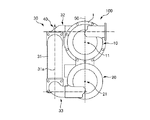
20 第二の筒状ケース
30 連結パイプ
31 直管部
32 連結部
40 還元剤供給ノズル
50 平面
100 内燃機関用の排ガス浄化装置
Claims (1)
- 排ガス流入口が一端側に設けられ当該一端側から順にDOC及びDPFが収納される第一の筒状ケースと、
排ガス流出口が一端側に設けられ当該一端側から順にアンモニアスリップ及びSCRが収納される第二の筒状ケースと、を備え、
前記第一の筒状ケースと前記第二の筒状ケースとが並列に配置されるとともに、第一の筒状ケースの前記一端側と第二の筒状ケースの前記一端側とが相互に反対向きとなるように配置されており、前記第一の筒状ケースの他端側と前記第二の筒状ケースの他端側とが連結パイプにより連結され、前記連結パイプの上流側に還元剤供給ノズルが設けられ、
前記連結パイプは、直管部と、その両端側の連結部と、を備え、
前記連結部は、いずれも前記第一の筒状ケース及び前記第二の筒状ケースの両軸を含む平面に対して同じ側から直交し、且つそれぞれが前記第一の筒状ケースの他端側若しくは前記第二の筒状ケースの他端側に対して接線方向に、前記第一の筒状ケース若しくは前記第二の筒状ケースの軸に対して前記第一の筒状ケース若しくは前記第二の筒状ケースの径方向にずれるように連結されており、前記還元剤供給ノズルが前記直管部の軸方向の上流側に設けられていることを特徴とする内燃機関用の排ガス浄化装置。
Priority Applications (1)
| Application Number | Priority Date | Filing Date | Title |
|---|---|---|---|
| JP2008003537A JP5114219B2 (ja) | 2008-01-10 | 2008-01-10 | 内燃機関用の排ガス浄化装置 |
Applications Claiming Priority (1)
| Application Number | Priority Date | Filing Date | Title |
|---|---|---|---|
| JP2008003537A JP5114219B2 (ja) | 2008-01-10 | 2008-01-10 | 内燃機関用の排ガス浄化装置 |
Publications (2)
| Publication Number | Publication Date |
|---|---|
| JP2009167806A JP2009167806A (ja) | 2009-07-30 |
| JP5114219B2 true JP5114219B2 (ja) | 2013-01-09 |
Family
ID=40969282
Family Applications (1)
| Application Number | Title | Priority Date | Filing Date |
|---|---|---|---|
| JP2008003537A Active JP5114219B2 (ja) | 2008-01-10 | 2008-01-10 | 内燃機関用の排ガス浄化装置 |
Country Status (1)
| Country | Link |
|---|---|
| JP (1) | JP5114219B2 (ja) |
Cited By (3)
| Publication number | Priority date | Publication date | Assignee | Title |
|---|---|---|---|---|
| CN105899776A (zh) * | 2014-01-10 | 2016-08-24 | 佛吉亚排放控制技术美国有限公司 | 用于排气组件的模块化混合器 |
| WO2019075877A1 (zh) * | 2017-10-18 | 2019-04-25 | 潍柴动力股份有限公司 | 一种通用化集成式doc-dpf-scr后处理装置 |
| US10787946B2 (en) | 2018-09-19 | 2020-09-29 | Faurecia Emissions Control Technologies, Usa, Llc | Heated dosing mixer |
Families Citing this family (22)
| Publication number | Priority date | Publication date | Assignee | Title |
|---|---|---|---|---|
| US8230678B2 (en) * | 2007-06-21 | 2012-07-31 | Daimler Trucks North America Llc | Treatment of diesel engine exhaust |
| KR101294061B1 (ko) * | 2011-07-11 | 2013-08-08 | 현대자동차주식회사 | 차량용 배기 가스 후처리 장치 |
| DE102011111590A1 (de) * | 2011-08-25 | 2013-02-28 | Volkswagen Aktiengesellschaft | Abgasbehandlungseinrichtung, Verfahren zur Aufbereitung von Abgas und Kraftfahrzeug |
| US8916100B2 (en) | 2011-12-27 | 2014-12-23 | Komatsu Ltd. | Reducing agent aqueous solution mixing device and exhaust gas post-treatment device |
| US8932530B2 (en) | 2011-12-27 | 2015-01-13 | Komatsu Ltd. | Reducing agent aqueous solution mixing device and exhaust gas post-treatment device |
| JP5349575B2 (ja) | 2011-12-27 | 2013-11-20 | 株式会社小松製作所 | 還元剤水溶液ミキシング装置及び排気ガス後処理装置 |
| CN104040125A (zh) * | 2012-01-06 | 2014-09-10 | 沃尔沃建造设备有限公司 | 用于减少重型设备的废气的装置 |
| JP5950631B2 (ja) * | 2012-03-09 | 2016-07-13 | 日野自動車株式会社 | 排気浄化装置 |
| US8893481B2 (en) * | 2013-01-17 | 2014-11-25 | Komatsu Ltd. | Reductant aqueous solution mixing device and exhaust aftertreatment device provided with the same |
| KR101360161B1 (ko) | 2013-01-17 | 2014-02-12 | 가부시키가이샤 고마쓰 세이사쿠쇼 | 환원제 수용액 믹싱 장치 및 이것을 구비한 배기 가스 후처리 장치 |
| JP5728578B2 (ja) * | 2013-01-17 | 2015-06-03 | 株式会社小松製作所 | 還元剤水溶液ミキシング装置およびこれを備えた排気ガス後処理装置 |
| US8991160B2 (en) * | 2013-01-17 | 2015-03-31 | Komatsu Ltd. | Reductant aqueous solution mixing device and exhaust aftertreatment device provided with the same |
| CN103498717A (zh) * | 2013-09-02 | 2014-01-08 | 上海创怡环境技术有限公司 | 巴士用doc+cdpf柴油引擎废气净化过滤系统 |
| JP6000931B2 (ja) | 2013-11-18 | 2016-10-05 | 株式会社クボタ | 作業車両 |
| US10138795B2 (en) | 2014-02-18 | 2018-11-27 | Faurecia Emissions Control Technologies, Usa, Llc | Plenum chamber for exhaust system |
| WO2016002973A1 (ja) | 2015-08-21 | 2016-01-07 | 株式会社小松製作所 | 油圧ショベル |
| JP6731307B2 (ja) * | 2016-07-28 | 2020-07-29 | 株式会社加藤製作所 | 排気浄化装置の取付構造 |
| CN108571367B (zh) * | 2017-03-10 | 2023-09-01 | 宇通客车股份有限公司 | 一种排气系统及使用该排气系统的车辆 |
| CN108868983B (zh) * | 2018-05-28 | 2019-12-17 | 安徽江淮汽车集团股份有限公司 | 一种集成式scr总成 |
| US10883411B2 (en) | 2018-06-06 | 2021-01-05 | Ford Global Technologies, Llc | Systems and methods for an exhaust-gas aftertreatment device |
| CN118030252A (zh) * | 2021-09-30 | 2024-05-14 | 宁波吉利罗佑发动机零部件有限公司 | 用于发动机排气净化处理的三效催化转化系统及其应用 |
| JP2024010905A (ja) * | 2022-07-13 | 2024-01-25 | ヤンマーホールディングス株式会社 | 排気ガス整流装置および排気ガス浄化システム |
Family Cites Families (3)
| Publication number | Priority date | Publication date | Assignee | Title |
|---|---|---|---|---|
| JP4785766B2 (ja) * | 2007-02-09 | 2011-10-05 | 日野自動車株式会社 | 排気浄化装置 |
| JP4785803B2 (ja) * | 2007-08-02 | 2011-10-05 | 日野自動車株式会社 | 排気浄化装置 |
| JP4286888B2 (ja) * | 2007-09-28 | 2009-07-01 | 日産ディーゼル工業株式会社 | 排気浄化装置 |
-
2008
- 2008-01-10 JP JP2008003537A patent/JP5114219B2/ja active Active
Cited By (5)
| Publication number | Priority date | Publication date | Assignee | Title |
|---|---|---|---|---|
| CN105899776A (zh) * | 2014-01-10 | 2016-08-24 | 佛吉亚排放控制技术美国有限公司 | 用于排气组件的模块化混合器 |
| US10287954B2 (en) | 2014-01-10 | 2019-05-14 | Faurecia Emissions Control Technologies Usa, Llc | Modular mixer for exhaust assembly |
| CN105899776B (zh) * | 2014-01-10 | 2019-07-23 | 佛吉亚排放控制技术美国有限公司 | 用于排气组件的模块化混合器 |
| WO2019075877A1 (zh) * | 2017-10-18 | 2019-04-25 | 潍柴动力股份有限公司 | 一种通用化集成式doc-dpf-scr后处理装置 |
| US10787946B2 (en) | 2018-09-19 | 2020-09-29 | Faurecia Emissions Control Technologies, Usa, Llc | Heated dosing mixer |
Also Published As
| Publication number | Publication date |
|---|---|
| JP2009167806A (ja) | 2009-07-30 |
Similar Documents
| Publication | Publication Date | Title |
|---|---|---|
| JP5114219B2 (ja) | 内燃機関用の排ガス浄化装置 | |
| US10989096B2 (en) | Close coupled single module aftertreatment system | |
| JP4951560B2 (ja) | 内燃機関用の排ガス浄化装置 | |
| US10576419B2 (en) | Single module integrated aftertreatment module | |
| JP4286888B2 (ja) | 排気浄化装置 | |
| JP6053096B2 (ja) | 排気浄化装置 | |
| JP5602495B2 (ja) | 排気ガス浄化装置 | |
| JP5066435B2 (ja) | ディーゼルエンジン用の排ガス浄化装置 | |
| JP4286887B2 (ja) | 排気浄化装置 | |
| JP5890661B2 (ja) | 排気浄化装置 | |
| WO2013099404A1 (ja) | 排気浄化装置 | |
| WO2017170108A1 (ja) | 排気浄化システム | |
| JP2008138654A (ja) | 排気ガス浄化装置 | |
| CN106471230B (zh) | 用于燃烧式发动机的排放气体后处理装置 | |
| JP2012092746A (ja) | 排気浄化装置 | |
| US10603641B2 (en) | Diesel exhaust fluid mixing body using variable cross-section switchback arrangement | |
| WO2017150513A1 (ja) | 内燃機関の排ガス浄化装置 | |
| US9528418B2 (en) | Single sensor monitoring system for multiple after-treatment systems on engines | |
| JP2020204286A (ja) | パイプ保温構造 | |
| WO2020189577A1 (ja) | ミキサー部材 | |
| JP2013167158A (ja) | 排気浄化装置 |
Legal Events
| Date | Code | Title | Description |
|---|---|---|---|
| A621 | Written request for application examination |
Free format text: JAPANESE INTERMEDIATE CODE: A621 Effective date: 20101220 |
|
| A977 | Report on retrieval |
Free format text: JAPANESE INTERMEDIATE CODE: A971007 Effective date: 20111222 |
|
| A131 | Notification of reasons for refusal |
Free format text: JAPANESE INTERMEDIATE CODE: A131 Effective date: 20111227 |
|
| A521 | Request for written amendment filed |
Free format text: JAPANESE INTERMEDIATE CODE: A523 Effective date: 20120223 |
|
| A131 | Notification of reasons for refusal |
Free format text: JAPANESE INTERMEDIATE CODE: A131 Effective date: 20120814 |
|
| A521 | Request for written amendment filed |
Free format text: JAPANESE INTERMEDIATE CODE: A523 Effective date: 20120828 |
|
| TRDD | Decision of grant or rejection written | ||
| A01 | Written decision to grant a patent or to grant a registration (utility model) |
Free format text: JAPANESE INTERMEDIATE CODE: A01 Effective date: 20120918 |
|
| A01 | Written decision to grant a patent or to grant a registration (utility model) |
Free format text: JAPANESE INTERMEDIATE CODE: A01 |
|
| A61 | First payment of annual fees (during grant procedure) |
Free format text: JAPANESE INTERMEDIATE CODE: A61 Effective date: 20121015 |
|
| FPAY | Renewal fee payment (event date is renewal date of database) |
Free format text: PAYMENT UNTIL: 20151019 Year of fee payment: 3 |
|
| R150 | Certificate of patent or registration of utility model |
Free format text: JAPANESE INTERMEDIATE CODE: R150 Ref document number: 5114219 Country of ref document: JP Free format text: JAPANESE INTERMEDIATE CODE: R150 |
|
| R250 | Receipt of annual fees |
Free format text: JAPANESE INTERMEDIATE CODE: R250 |
|
| R250 | Receipt of annual fees |
Free format text: JAPANESE INTERMEDIATE CODE: R250 |
|
| R250 | Receipt of annual fees |
Free format text: JAPANESE INTERMEDIATE CODE: R250 |
|
| R250 | Receipt of annual fees |
Free format text: JAPANESE INTERMEDIATE CODE: R250 |
|
| R250 | Receipt of annual fees |
Free format text: JAPANESE INTERMEDIATE CODE: R250 |
|
| R250 | Receipt of annual fees |
Free format text: JAPANESE INTERMEDIATE CODE: R250 |
|
| R250 | Receipt of annual fees |
Free format text: JAPANESE INTERMEDIATE CODE: R250 |
|
| R250 | Receipt of annual fees |
Free format text: JAPANESE INTERMEDIATE CODE: R250 |
|
| R250 | Receipt of annual fees |
Free format text: JAPANESE INTERMEDIATE CODE: R250 |
|
| R250 | Receipt of annual fees |
Free format text: JAPANESE INTERMEDIATE CODE: R250 |
|
| R250 | Receipt of annual fees |
Free format text: JAPANESE INTERMEDIATE CODE: R250 |