JP5114586B2 - Roadside snow removal device and roadside snow removal method - Google Patents
Roadside snow removal device and roadside snow removal method Download PDFInfo
- Publication number
- JP5114586B2 JP5114586B2 JP2011135417A JP2011135417A JP5114586B2 JP 5114586 B2 JP5114586 B2 JP 5114586B2 JP 2011135417 A JP2011135417 A JP 2011135417A JP 2011135417 A JP2011135417 A JP 2011135417A JP 5114586 B2 JP5114586 B2 JP 5114586B2
- Authority
- JP
- Japan
- Prior art keywords
- snow
- snow removal
- road
- safety fence
- avalanche
- Prior art date
- Legal status (The legal status is an assumption and is not a legal conclusion. Google has not performed a legal analysis and makes no representation as to the accuracy of the status listed.)
- Expired - Fee Related
Links
Images


Landscapes
- Cleaning Of Streets, Tracks, Or Beaches (AREA)
Description
本発明は、積雪に埋もれている道路用ガードレールやガードロープ(以下、道路用安全柵と称する。)を露出させて交通の安全を確保し、また積雪の融雪を促進する路肩除雪装置及び路肩の除雪方法に関する。 The present invention exposes road guard rails and guard ropes (hereinafter referred to as road safety fences) buried in snow to ensure traffic safety and promotes road shoulder snow removal devices and road shoulders. It relates to a snow removal method.
降雪地における道路用ガードレールやガードロープの道路用安全柵には、雪が付着して雪塊状に堆積し、また道路から排除された雪が押し付けられて堆積することによって、積雪の中に埋まった状態になる。
しかし、従来は積雪に埋まった道路用安全柵を除雪により露出させるための専用の除雪機は無いし、車道の除雪は路肩に雪壁を形成した状態であるために道路用安全柵は半ば埋まった状態になっている。
Snow guards and guard rope road safety fences in snowy areas accumulate snow in a lump, and the snow removed from the road is pushed and accumulated, leaving it buried in snow. Become.
However, in the past, there was no dedicated snow remover to expose the road safety fence buried in snow by removing snow, and the road safety fence was partially buried because the snow removal on the roadway was in the state of forming a snow wall on the shoulder. It is in the state.
また、歩道は小型作業車で除雪を行うが、道路用安全柵の脇は積雪が残っていることから、道路用安全柵と歩道との間に積雪が堤状に残ったままになっているのが現状である。 In addition, snow is removed from the sidewalk using a small work vehicle, but snow remains on the side of the road safety fence, so the snow remains in the shape of a bank between the road safety fence and the sidewalk. is the current situation.
このため、雪壁や積雪の堤は、その上端側の雪が強風で車道側に吹き飛ばされて車両運転者の視界を妨げることにより車両事故を招くという問題や、交差点で左右方向の視界を妨げて出会い頭の車両事故を招くという問題を生じている。歩行者も交差点で堤状の積雪から車両が突然現われるといった危険に出会っているのが現状である。 For this reason, snow walls and snow crests can cause problems such as causing a vehicle accident by causing snow on the upper end side to be blown off to the roadway by strong winds and obstructing the vehicle driver's view, and obstructing the lateral view at the intersection. There is a problem of causing a car accident at the meeting. At present, pedestrians are also faced with the danger that a vehicle suddenly appears from a bank-like snow cover at an intersection.
本発明は上述した従来技術の未解決の問題点に鑑みなされたもので、道路用安全柵の両側を除雪して道路用安全柵を雪から露出させることで、雪の飛散や視界不良による車両事故の防止、歩行者の歩行安全を確保することができる路肩除雪装置及び路肩の除雪方法を提供することを目的とする。 The present invention has been made in view of the above-mentioned unsolved problems of the prior art, and by removing snow on both sides of the road safety fence and exposing the road safety fence from the snow, the vehicle due to snow scattering and poor visibility An object of the present invention is to provide a roadside snow removal device and a roadside snow removal method capable of preventing accidents and ensuring the walking safety of pedestrians.
上述した課題を解決するために構成した本発明の手段は、路肩に沿って立設する道路用安全柵を埋める積雪を排除する路肩除雪装置であって、作業車に取着する支持体と、該支持体に基端側が軸支されて前記作業車の横方向に突出し、前記道路用安全柵を越える先端側は上下方向に回動可能な可動アームと、該可動アームの先端に設けられ、前記道路用安全柵の外側の積雪を排除する除雪ブレードと、前記可動アームの長手方向略中間に配置され、前記道路用安全柵の内側の積雪を排除する雪崩し板を有する雪崩し機構とからなる。 The means of the present invention configured to solve the above-mentioned problem is a road shoulder snow removal device that eliminates snow accumulation that fills a road safety fence erected along a road shoulder, and a support attached to a work vehicle, A base end side is pivotally supported by the support body and protrudes in the lateral direction of the work vehicle, and a distal end side that exceeds the road safety fence is provided at a distal end of the movable arm, and a movable arm that is rotatable in a vertical direction. A snow removal blade that eliminates snow accumulation outside the road safety fence, and an avalanche mechanism that is disposed approximately in the longitudinal direction of the movable arm and has an avalanche plate that eliminates snow accumulation inside the road safety fence. Become.
そして、前記除雪ブレードは、下側除雪ブレードと上側除雪ブレードから構成し、該下側除雪ブレードは上側除雪ブレードより進行方向前側に位置させるとよい。 The snow removal blade may be composed of a lower snow removal blade and an upper snow removal blade, and the lower snow removal blade may be positioned forward of the upper snow removal blade in the traveling direction.
また、前記雪崩し機構は、下端に路面滑走体を設けるとよい。 The avalanche mechanism may be provided with a road surface sliding body at the lower end.
また、前記雪崩し板は、前記除雪ブレードより進行方向後側に位置させるとよい。 The avalanche plate may be positioned behind the snow removal blade in the traveling direction.
更に、前記雪崩し機構は、前記可動アームに進退可能に設けるとよい。 Furthermore, the avalanche mechanism may be provided on the movable arm so as to be able to advance and retract.
また、前記雪崩し機構は、硬化した積雪を上下に切断する雪切断刃を備えているとよい。 The avalanche mechanism may include a snow cutting blade that cuts the hardened snow up and down.
また、請求項7に係る本発明を構成する手段は、路肩に沿って立設する道路用安全柵の外側に位置する除雪ブレードと内側に位置する雪崩し板を作業車から横方向に突出した状態で搭載し、該作業車を走行させながら前記道路用安全柵の外側の積雪は前記除雪ブレードにより排除し、道路用安全柵の内側の積雪は前記雪崩し板により排除するようにしてなる。 According to a seventh aspect of the present invention, there is provided a means for projecting a snow removing blade located outside a road safety fence standing along a road shoulder and an avalanche board located inside from a work vehicle in a lateral direction. The snowboard outside the road safety fence is removed by the snow removal blade while the work vehicle is running, and the snow accumulation inside the road safety fence is eliminated by the snow throwing plate.
本発明は上述の如く構成したから、下記の諸効果を奏する。
(1)路肩に沿って立設する道路用安全柵の外側の積雪は除雪ブレードにより、内側の積雪は雪崩し板により夫々排除し、道路用安全柵が可及的に露出するようにしたから、強風時の雪の飛散を防止し、また交差点での視界を確保することにより出会い頭の衝突を回避することで交通の安全を確保することができる。
(2)除雪により道路用安全柵を積極的に露出させるようにしたから、道路用安全柵に付着している雪塊も輻射熱により溶解が促進され、従来に比して早い時期に道路用安全柵を略完全に露出させることができる。
(3)除雪ブレードは、下側除雪ブレードと上側除雪ブレードから構成し、進行方向前側に位置する下側除雪ブレードが積雪の下側部を先に除雪することで積雪の上側部は崩れ易くなり、上側除雪ブレードの受ける抵抗が減少するので作業効率を高めることができる。
(4)雪崩し機構の下端に路面滑走体を設けることで、除雪作業中に路面を損傷する事態を防止し、また路面に対する雪崩し板の高さを略一定に保って正確な除雪作業を可能にする。
(5)雪崩し板は排雪ブレードより進行方向後側に位置させることで、積雪は薄い壁状になるから、雪崩し板は容易に積雪を崩すことができ、積雪残りといった事態を解消できる。
(6)雪崩し機構は可動アームに進退可能に設けるから、道路上の設置物を回避しながら除雪することができる。
(7)雪崩し機構は凍結により硬化した積雪を上下に切断する雪切断刃を備えているから、凍結状態の積雪を上下に切断することで除雪作業を円滑に行うことができる。
Since the present invention is configured as described above, the following effects can be obtained.
(1) Because the snow outside the road safety fence standing along the shoulder is removed by a snow removal blade, the snow inside is removed by an avalanche plate, and the road safety fence is exposed as much as possible. Traffic safety can be ensured by preventing snow splashes during strong winds and avoiding collisions at the intersections by ensuring visibility at intersections.
(2) Since the road safety fence is actively exposed by removing snow, melting of the snow mass adhering to the road safety fence is promoted by radiant heat, and the road safety is earlier than before. The rail can be exposed almost completely.
(3) The snow removal blade is composed of a lower snow removal blade and an upper snow removal blade. The lower snow removal blade located on the front side in the traveling direction removes the lower part of the snow first, so that the upper part of the snow easily collapses. Since the resistance received by the upper snow removal blade is reduced, work efficiency can be improved.
(4) By providing a road surface sliding body at the lower end of the avalanche mechanism, it is possible to prevent the road surface from being damaged during the snow removal work, and to maintain the height of the avalanche plate with respect to the road surface to be substantially constant for accurate snow removal work. enable.
(5) By placing the avalanche plate on the rear side in the direction of travel from the snow discharge blade, the snow cover becomes a thin wall, so the avalanche plate can easily collapse the snow cover and eliminate the remaining snow cover. .
(6) Since the avalanche mechanism is provided on the movable arm so as to be able to advance and retreat, snow can be removed while avoiding the installation on the road.
(7) Since the snow avalanche mechanism includes a snow cutting blade that cuts up and down the snow that has hardened by freezing, the snow removal operation can be performed smoothly by cutting up and down the frozen snow.
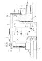
以下、本発明の実施の形態を図面に基づき詳述する。図において、1は路肩除雪装置を構成する支持体を示す。該支持体1はホイールローダ等の作業車Hに固定する鋼板製の取付け板1Aと、該取付け板1A上に矢示イ、ロ方向の水平方向に回動可能に立設した角型鋼管からなる縦支柱1Bと、該縦支柱1Bを回転駆動する油圧駆動機1Cとから構成してあり、除雪作業を行わない場合や市街を走行する場合は、後述する可動アーム2を作業車Hの前方或いは後方に回転させることにより作業車Hの内側に格納可能にしてある。
Hereinafter, embodiments of the present invention will be described in detail with reference to the drawings. In the figure,
2は前記縦支柱1Bの上端側に基端側2Aが軸支され、作業車Hの横方向に突出する可動アームを示す。該可動アーム2は該基端側2Aと縦支柱1Bとの間に連結した昇降用油圧シリンダ3によって先端2B側が矢示ハ、ニ方向の上下方向に昇降可能になっており、車道側から道路安全柵Gを越えて外側に上下動できるようになっている。なお、昇降用油圧シリンダ3及び後述する他の油圧シリンダ7、9の作動油は作業車Hから供給するようにしてある。
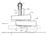
4は前記可動アーム2の先端2Bから垂設し、道路用安全柵Gの外側、即ち車道と反対側の積雪を排除するための除雪機構を示す。該除雪機構4は可動アーム2の先端2Bから垂設した支柱4Aと、該支柱4Aの下端側に設けた下側除雪ブレード4Bと、該下側除雪ブレード4Bの上方に配置した上側除雪ブレード4Cとから構成してあり、両ブレード4B、4Cは前面が凹状湾曲面に形成してある。そして、下側除雪ブレード4Bは支柱4Aの下側を前方に屈曲させることで上側除雪ブレード4Cよりも矢示ホの走行方向に向けて前側に若干進出させてあり、上側除雪ブレード4Cより先行して積雪Sの下側部分を抉って排除するように位置させてある。
5は可動アーム2の途中に配設した雪崩し機構を示す。6は該雪崩し機構5を構成する支持腕で、該支持腕6は可動アーム2に摺動可能に挿嵌した角筒状の摺動嵌合体6Aと、該摺動嵌合体6Aの側面から下向きに突設した支柱本体6Bと、前後端が上向きに湾曲した橇状をなし、該支柱本体6Aの下端に固着されて積雪道路面上を滑動する路面滑走体6Cと、支柱本体6Aの下端側に先端を上向きにして固着した支持ピン6Dとから構成してある。そして、支持腕6は可動アーム2との間に設けた進退用油圧シリンダ7によって矢示へ、ト方向に進退可能になっている。
8は雪崩し機構5を構成する雪崩し板で、該雪崩し板8は横長の鋼板を略く字状に屈曲させた板本体8Aと、該板本体8Aの基端に形成した連結筒8Bとから形成してあり、連結筒8Bを前記支持ピン6Dに挿嵌することに矢示チ、リ方向の前後方向に回動可能に支持されている。9は該雪崩し板8を前後に揺動させ、或いは積雪Sに接近させるための前後動用油圧シリンダで、該前後動用油圧シリンダ9は支持腕6の下端から横方向に突設した取付け軸9Aの先端に支持させてあり、ピストンロッドは雪崩し板8の背面に枢着してある。
本実施の形態に係る路肩除雪装置は上述の構成からなるもので、次にその作用について説明する。先ず、可動アーム2を矢示ハ、ニ方向に昇降操作することにより、下側除雪ブレード4B及び上側除雪ブレード4Cを道路用安全柵Gの外側、即ち車道の反対側で、かつ道路用安全柵Gの横側に位置させる。また、雪崩し機構5の支持腕6を進退用油圧シリンダ7によって矢示へ、ト方向に前後させ、雪崩し板8を道路用安全柵Gに接近させた状態に設定する。
The road shoulder snow removal device according to the present embodiment has the above-described configuration, and the operation thereof will be described next. First, by moving the
しかる後、作業車Hを矢示ホ方向に前進させると、先ず下側除雪ブレード4Bが道路用安全柵Gに沿って前進し、道路用安全柵Gを埋めるように堆積している積雪Sの下半分を排除する。これにより、支えの無くなった積雪の上半分は崩れ易くなり、上側除雪ブレード4Cは大きな抵抗を受けることなく道路用安全柵Gの積雪を外側に除雪することができる。 After that, when the work vehicle H is advanced in the direction of arrow E, the lower snow removal blade 4B first advances along the road safety fence G, and the snow accumulation S accumulated so as to fill the road safety fence G is obtained. Eliminate the lower half. As a result, the upper half of the snow cover that is no longer supported tends to collapse, and the upper snow removal blade 4C can remove the snow accumulation on the road safety fence G to the outside without receiving a large resistance.
また、道路用安全柵Gに沿って車道側に雪壁状に形成されている積雪は、外側の積雪が先に排除されたことで崩れ易くなっており、ここで雪崩し板8が積雪を側方から押圧することで道路側の積雪も容易に崩すことができる。この際、前後動用油圧シリンダ9によって雪崩し板8を矢示チ、リ方向の前後に揺動することで積雪を速やかに崩すことができるし、或いは矢示チ又はリ方向に回転させて道路用安全柵Gに雪崩し板8が当たらないように間隔を調整することも可能である。
In addition, the snow cover that is formed in the shape of a snow wall on the roadway side along the road safety fence G is easy to collapse because the outer snow cover has been removed first, and here the
本実施の形態による路肩除雪装置は、このようにして路側に形成されている積雪Sを排除することで、吹雪により雪が飛散して視界を妨げたり、交差点で出会い頭に衝突するといった事故の発生を解消することができるのであり、交通安全に多大な貢献を果すことができるものである。 The roadside snow removal device according to the present embodiment eliminates the snow accumulation S formed on the roadside in this way, thereby preventing the occurrence of an accident such as snow scattering from a snowstorm and obstructing the field of view or colliding with the head of an intersection. It can be eliminated and can make a great contribution to road safety.
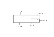
次に、図5乃至図7に本実施の形態の変形例を示す。図において、11は雪崩し機構、12は該雪崩し機構11を構成する雪崩し板を示す。該雪崩し板12は横長の鋼板からなる板本体12Aと、該板本体12Aの縦幅の中間に先端から内側に切込み12Bを設けることで板本体12Aに形成した上側湾曲片12C及び下側湾曲片12Dと、板本体12Aの基端側に形成した連結筒12Eとから構成してある。
Next, FIGS. 5 to 7 show modifications of the present embodiment. In the figure, 11 is an avalanche mechanism, and 12 is an avalanche plate constituting the
上述の構成からなる雪崩し板12は、連結筒12Eを支持腕6の支持ピン6Dに挿嵌し、進退用油圧シリンダ7を連結して支持腕6に設ける。そして、雪崩し板12は、上側湾曲片12Cを下側湾曲片12Dより前方に突出させた形状にすることで、柔らかい積雪Sの上部分と下部分を僅かな時間差で崩すことで雪の飛散を防止しながら除雪するようにするものである。
The
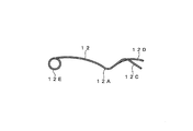
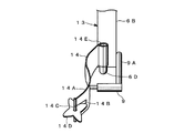
図8乃至図10は第2の変形例を示す。図において、13は雪崩し機構、14は該雪崩し機構13を構成する雪崩し板を示す。該雪崩し板14は横長の鋼板からなり、先端に軸支持管を形成した板本体14Aと、該板本体14Aの縦幅の中間に先端から内側に形成したスリット14Bと、前記軸支持管に挿装した支持軸14Cに回動可能に設けた略十字状の雪切断刃14Dと、板本体14Aの基端側に形成した連結筒14Eとから構成してある。
8 to 10 show a second modification. In the figure, 13 indicates an avalanche mechanism, and 14 indicates an avalanche plate constituting the avalanche mechanism 13. The
上述の構成からなる雪崩し板14は支持ピン6Dにより支持し、進退用油圧シリンダ7により前後に揺動可能になっており、気温の寒暖により凍結した積雪Sを前進しながら上下に切断することで、積雪Sを崩し易くするものである。
The
1 支持体
2 可動アーム
4B 下側除雪ブレード
4C 上側除雪フレード
5、11、13 雪崩し機構
6C 路面滑走体
8、12 雪崩し板
14 雪切断刃
DESCRIPTION OF
Claims (7)
Priority Applications (1)
| Application Number | Priority Date | Filing Date | Title |
|---|---|---|---|
| JP2011135417A JP5114586B2 (en) | 2011-06-17 | 2011-06-17 | Roadside snow removal device and roadside snow removal method |
Applications Claiming Priority (1)
| Application Number | Priority Date | Filing Date | Title |
|---|---|---|---|
| JP2011135417A JP5114586B2 (en) | 2011-06-17 | 2011-06-17 | Roadside snow removal device and roadside snow removal method |
Publications (2)
| Publication Number | Publication Date |
|---|---|
| JP2013002173A JP2013002173A (en) | 2013-01-07 |
| JP5114586B2 true JP5114586B2 (en) | 2013-01-09 |
Family
ID=47671035
Family Applications (1)
| Application Number | Title | Priority Date | Filing Date |
|---|---|---|---|
| JP2011135417A Expired - Fee Related JP5114586B2 (en) | 2011-06-17 | 2011-06-17 | Roadside snow removal device and roadside snow removal method |
Country Status (1)
| Country | Link |
|---|---|
| JP (1) | JP5114586B2 (en) |
Cited By (1)
| Publication number | Priority date | Publication date | Assignee | Title |
|---|---|---|---|---|
| JP2947484B2 (en) | 1990-05-08 | 1999-09-13 | 雪印乳業株式会社 | Bone-fortified food, feed or osteoarthritis prophylactic or therapeutic drug |
Families Citing this family (1)
| Publication number | Priority date | Publication date | Assignee | Title |
|---|---|---|---|---|
| CN111636345B (en) * | 2020-06-29 | 2024-11-22 | 康洁科技集团有限公司 | Automatic adjustment mechanism for the height of the vertical brush of the sweeper |
Family Cites Families (2)
| Publication number | Priority date | Publication date | Assignee | Title |
|---|---|---|---|---|
| JP4697983B2 (en) * | 2008-03-13 | 2011-06-08 | 藤元建設工業株式会社 | Guardrail cleaning and painting equipment |
| JP2009275435A (en) * | 2008-05-15 | 2009-11-26 | Kawasaki Heavy Ind Ltd | Bucket for snow plow |
-
2011
- 2011-06-17 JP JP2011135417A patent/JP5114586B2/en not_active Expired - Fee Related
Cited By (1)
| Publication number | Priority date | Publication date | Assignee | Title |
|---|---|---|---|---|
| JP2947484B2 (en) | 1990-05-08 | 1999-09-13 | 雪印乳業株式会社 | Bone-fortified food, feed or osteoarthritis prophylactic or therapeutic drug |
Also Published As
| Publication number | Publication date |
|---|---|
| JP2013002173A (en) | 2013-01-07 |
Similar Documents
| Publication | Publication Date | Title |
|---|---|---|
| CN102877433B (en) | Front combined type snow removing device for snow removing vehicle | |
| JP5114586B2 (en) | Roadside snow removal device and roadside snow removal method | |
| KR101346141B1 (en) | Brush sweeper of snowplow car for runway with improved snow removal efficiency | |
| US10072387B2 (en) | Side snowplow including land leveler | |
| KR20150041492A (en) | Blade type snowplow for vehicle mounting | |
| SE525314C2 (en) | Snow removal device from motor vehicles | |
| CN110528416B (en) | A kind of snow removal method using speed bumps to remove snow | |
| CN108049330A (en) | A kind of urban road safety height-limiting device | |
| US5729919A (en) | Plow blade | |
| KR102148568B1 (en) | Snow removal vehicle | |
| JP3682216B2 (en) | Snow removal unit | |
| US6439803B1 (en) | Snowplowable pavement marker | |
| CN202243303U (en) | Motor vehicle advancing barrier removing device | |
| KR20140014471A (en) | Machine for crushing pavement having wheel and crushing method of pavement using it | |
| KR200414508Y1 (en) | Snow plow with retractable shatterproof device | |
| CN212515011U (en) | A radar detection device | |
| JP5873347B2 (en) | Road shoulder residual snow shaping method and road shoulder residual snow shaping machine | |
| RU2465393C1 (en) | Snow removal blade | |
| KR102284931B1 (en) | Safety Bollard System for Pedestrian Protection | |
| KR200422656Y1 (en) | Snow Blowers with Extended Snow Plows | |
| CN209429013U (en) | A kind of traffic engineering expressway barrier | |
| US9441338B2 (en) | Snowplow blade | |
| CN221218389U (en) | Device is pour to curb back of being convenient for | |
| CN216640422U (en) | Snow removing equipment for road | |
| JPH0327056Y2 (en) |
Legal Events
| Date | Code | Title | Description |
|---|---|---|---|
| TRDD | Decision of grant or rejection written | ||
| A01 | Written decision to grant a patent or to grant a registration (utility model) |
Free format text: JAPANESE INTERMEDIATE CODE: A01 |
|
| A61 | First payment of annual fees (during grant procedure) |
Free format text: JAPANESE INTERMEDIATE CODE: A61 Effective date: 20121015 |
|
| FPAY | Renewal fee payment (event date is renewal date of database) |
Free format text: PAYMENT UNTIL: 20151019 Year of fee payment: 3 |
|
| R150 | Certificate of patent or registration of utility model |
Ref document number: 5114586 Country of ref document: JP Free format text: JAPANESE INTERMEDIATE CODE: R150 Free format text: JAPANESE INTERMEDIATE CODE: R150 |
|
| R250 | Receipt of annual fees |
Free format text: JAPANESE INTERMEDIATE CODE: R250 |
|
| R250 | Receipt of annual fees |
Free format text: JAPANESE INTERMEDIATE CODE: R250 |
|
| R250 | Receipt of annual fees |
Free format text: JAPANESE INTERMEDIATE CODE: R250 |
|
| R250 | Receipt of annual fees |
Free format text: JAPANESE INTERMEDIATE CODE: R250 |
|
| R250 | Receipt of annual fees |
Free format text: JAPANESE INTERMEDIATE CODE: R250 |
|
| LAPS | Cancellation because of no payment of annual fees |