JP5114613B2 - Bulletin board - Google Patents
Bulletin board Download PDFInfo
- Publication number
- JP5114613B2 JP5114613B2 JP2005319935A JP2005319935A JP5114613B2 JP 5114613 B2 JP5114613 B2 JP 5114613B2 JP 2005319935 A JP2005319935 A JP 2005319935A JP 2005319935 A JP2005319935 A JP 2005319935A JP 5114613 B2 JP5114613 B2 JP 5114613B2
- Authority
- JP
- Japan
- Prior art keywords
- board
- holding means
- posting
- leg portion
- poster
- Prior art date
- Legal status (The legal status is an assumption and is not a legal conclusion. Google has not performed a legal analysis and makes no representation as to the accuracy of the status listed.)
- Expired - Fee Related
Links
Images





Landscapes
- Supports Or Holders For Household Use (AREA)
Description
本発明は、ポスター等の掲示物を貼り付けた状態に保持する掲示具及び保持手段に関する。 The present invention relates to a posting tool and holding means for holding a posting such as a poster in a pasted state.
従来から、ポスターを掲示するための掲示板について案出されている(例えば、特許文献1参照。)。この掲示板は、ポスターを掲示するために繰り返して使用でき、ポスターを確実且つ容易に、しかも外観よく掲示し得るように考慮されている。しかし、どんな大きさの掲示物でも画鋲やマグネット無しで、より容易且つ確実に掲示でき、しかも外観上も、より好ましい掲示具が望まれている。
そこで、本発明者は、このような課題の原因を究明してこのような課題を解決するべく、鋭意研究を重ねた結果、本発明に至ったのである。 Therefore, the inventor of the present invention has come to the present invention as a result of intensive studies to investigate the cause of such a problem and solve such a problem.
すなわち、本発明は、より容易且つ確実に掲示でき、しかも外観上より好ましい掲示具及び保持手段を提供することを目的とする。 That is, an object of the present invention is to provide a display tool and a holding means that can be posted more easily and reliably and are more preferable in appearance.
本発明の掲示具は、弾性部材から成り複数の貫通孔を有するボードと、前記ボード表面に掲示物を貼り付けた状態に保持する複数の保持手段と、を備え、前記保持手段が、前記貫通孔に挿入される脚部と、該脚部に連続し前記ボードに向かって弾性的に付勢力を付与される頭部と、を有し、前記頭部と前記ボードとの間で前記掲示物を押圧して挟持することを特徴とする。 The bulletin board of the present invention comprises a board made of an elastic member and having a plurality of through holes, and a plurality of holding means for holding the posting object in a state of being attached to the surface of the board, wherein the holding means is the through hole. A leg portion inserted into the hole, and a head portion that is continuous with the leg portion and is elastically applied with a biasing force toward the board, and the posted article between the head portion and the board. It is characterized by pressing and holding.
本発明の掲示具は、前記掲示具において、前記保持手段が、前記頭部の端部付近を押して前記ボードに対して弾性的に回動させることにより、前記掲示物の挟持又は解除を行うように構成されたことを特徴とする。 In the bulletin board according to the present invention, in the bulletin board, the holding means pushes the vicinity of the end portion of the head and elastically rotates it with respect to the board, thereby clamping or releasing the bulletin board. It is characterized by being configured.
本発明の掲示具は、前記掲示具において、前記保持手段が、前記ボードに向かって突出する突起部を有することを特徴とする。 The bulletin board according to the present invention is characterized in that, in the bulletin board, the holding means has a protrusion protruding toward the board.
本発明の掲示具は、前記掲示具において、前記脚部及び前記貫通孔が多角形断面を有することにより、該脚部が該貫通孔に対して回動不可能であることを特徴とする。 The posting tool of the present invention is characterized in that, in the posting tool, the leg portion and the through hole have a polygonal cross section so that the leg portion cannot rotate with respect to the through hole.
本発明の掲示具は、前記掲示具において、前記脚部が、前記ボードの裏面側に膨出する拡幅部を備えたことを特徴とする。 The bulletin board according to the present invention is characterized in that, in the bulletin board, the leg portion includes a widened portion that bulges to the back side of the board.
本発明の保持手段は、弾性部材から成り複数の貫通孔を有するボードの表面に掲示物を貼り付けた状態に保持するための保持手段であり、前記貫通孔に挿入される脚部と、該脚部に連続し前記ボードに向かって弾性的に付勢力を付与される頭部と、を有し、前記頭部と前記ボードとの間で前記掲示物を押圧して挟持することを特徴とする。 The holding means of the present invention is a holding means for holding a posting on a surface of a board made of an elastic member and having a plurality of through holes, and a leg portion inserted into the through hole, A head portion that is continuous with the leg portion and elastically applied with an urging force toward the board, and presses and holds the posting between the head portion and the board. To do.
本発明の掲示具及び保持手段によれば、保持手段を指で押すことのみによって掲示物の取り付け又は取り外しができる。このため、より容易且つ確実に掲示物を貼り付けることができる。また、複数の保持手段をボードの表面に整列して取り付けておけば、外観上も好ましい。 According to the posting tool and the holding means of the present invention, the posting object can be attached or detached only by pushing the holding means with a finger. For this reason, a posting thing can be stuck more easily and reliably. Further, if a plurality of holding means are aligned and attached to the surface of the board, it is preferable in terms of appearance.
次に、本発明に係る掲示具及び保持手段の実施の形態について、図面に基づいて詳しく説明する。 Next, embodiments of the posting tool and the holding means according to the present invention will be described in detail with reference to the drawings.
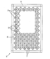
図1乃至図3において、符号10は、本発明の掲示具であり、符号12は、本発明の保持手段である。
In FIG. 1 to FIG. 3,
掲示具10は、弾性部材から成り複数の貫通孔14を有するボード16と、ボード16表面にポスター(掲示物)18を貼り付けた状態に保持する複数の保持手段12と、を備えている。
The
保持手段12は、貫通孔14に挿入される脚部22と、脚部22に連続しボード16に向かって弾性的に付勢力を付与される頭部24と、を有し、頭部24とボード16との間でポスター18を押圧して挟持するように構成されている。また、保持手段12は、頭部24の端部付近を図3に示すように指で押すことにより、ボード16に対して弾性的に回動させ、これによりポスター18の挟持又は解除を行うことができるように構成されている。さらに、保持手段12は、ボード16に向かって突出する突起部26を有し、この突起部26をポスター18に突刺してポスター18が落下しないように保持できるように構成されている。
The holding means 12 includes a
この保持手段12の脚部22及びボード16の貫通孔14は、正方形断面(多角形断面)を有し、貫通孔14に挿入した脚部22が貫通孔14に対して回動不可能であるように構成されている。また、脚部22は、ボード16の裏面側に膨出する拡幅部28を有し、脚部22がボード16から抜出するのを防止できるように構成されている。この拡幅部28の先端側は、貫通孔14に挿入しやすいようにテーパ部30を有している。
The
この掲示具10は、長方形のボード16に枠32及び周囲カバー34を取り付け、ボード16の複数の貫通孔14に複数の保持手段12を挿入して固定することにより製造される。ボード16の材質は、弾性部材であれば、樹脂、木材、ゴム等、特に限定されない。また、保持手段12の材質は、変形しないものであれば特に限定されない。
The
このような構成の本発明に係る掲示具10及び保持手段12の作用及び効果について以下に説明する。
The operation and effect of the
掲示具10にポスター18を貼り付ける場合、図3に示すように、保持手段12の頭部24の上方の端部付近を指36で押して保持手段12をボード16に対して弾性的に回動させることにより、頭部24の下方の裏側に隙間を生じさせた状態で、ポスター18をその隙間に下から挿入し、指36を放す。これにより、図1に示すように、頭部24とボード16との間でポスター18が押圧されて挟持される。図1においては、ポスター18は6個の保持手段12によって挟持されている。
When the
この時、ボード16の弾性力によってポスター18に頭部24から付勢力が付与されることにより、頭部24とボード16との間でポスター18が押圧されて挟持される。また、突起部26がポスター18に突刺されることにより、ポスター18は安定して保持され、風や揺れによってもポスター18が頭部24とボード16との間から外れて落下することはない。
At this time, the
次に、ポスター18を取り外す必要が生じた場合、図3に示すように、保持手段12の頭部24の上方の端部付近を指36で押して保持手段12をボード16に対して弾性的に回動させることにより、頭部24の下方の裏側に隙間を生じさせた状態で、ポスター18をその隙間から取り外す。また、不要となったポスター18の場合には、ポスター18の下部付近を手で強く持って下へ引き、ポスター18の上部付近を破砕しながら取り外しても良い。
Next, when it becomes necessary to remove the
このような掲示具10及び保持手段12によれば、上記のように、保持手段12を指36で押すことのみによってポスター18の取り付け又は取り外しができる。このため、より容易且つ確実にポスター18を貼り付けることができる。また、複数の保持手段12をボード16の表面に整列して取り付けておけば、外観上も好ましい。特に、図1に示すように、正方形の頭部24を45°に傾斜させ、頭部24同志の隙間の幅が一定になるように等間隔で整列させれば、鱗状の模様を描くため、外観上好ましい。
According to the
頭部24の端部付近を押すことによって、保持手段12をボード16に対して弾性的に回動させてポスター18の挟持又は解除を行う構造であるため、バネ等の付勢手段を特に設ける必要がない。このため、掲示具10及び保持手段12をコンパクトに構成でき、これにより外観も好ましくなる。
By pressing the vicinity of the end of the
また、保持手段12の脚部22及びボード16の貫通孔14が、正方形断面を有し、貫通孔14に挿入した脚部22が貫通孔14に対して回動不可能であるため、保持手段12が貫通孔14に対して自由回動して保持する突起部26の位置が不規則に変わってしまうことがない。このため、確実に突起部26をポスター18に突刺して容易にポスター18を保持できる。
Further, since the
また、脚部22の拡幅部28によって脚部22がボード16から抜出するのを防止する構造であるため、抜け止め手段を別途設ける必要がない。また、テーパ部30からボード16に圧入して容易に取り付けることができる。また、ボード16が弾性部材であるため、頭部24を保持して強く抜き出せば、容易に取り外すことができる。
In addition, since the
以上、本発明の一実施形態について図面に基いて説明したが、本発明は、上述した実施形態には限定されない。 As mentioned above, although one Embodiment of this invention was described based on drawing, this invention is not limited to embodiment mentioned above.
例えば、掲示具10において、図4に示すように、ポスター18を保持しない保持手段12を取り外し、ポスター18を保持する保持手段12のみを残しても良い。この場合、取り外した保持手段12は、他の掲示具10のために利用できる。
For example, in the
また、掲示具10において、図5に示すように、保持手段12及び貫通孔14を図1の場合よりも少なく構成しても良い。この場合でも、保持手段12を等間隔で整列しているとともに貫通孔14が見えないため、外観上好ましい。なお、ボード16は、周囲の環境に対応した色彩にすることが望ましい。
Moreover, in the
また、保持手段は図6に示すような保持手段50であっても良い。この保持手段50は、円形断面を有する脚部52と円形の頭部54とを備えている。この場合、貫通孔56も円形断面を有しており、脚部52が貫通孔56に対して自由回動する。このため、確実に突起部26をポスター18に突刺するためには、突起部26を頭部54の外周に沿って多数個設けておくことが望ましい。
Further, the holding means may be a holding means 50 as shown in FIG. The holding means 50 includes a
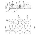
また、保持手段12において、図7に示すように、図2のような突起部26を設けなくとも良い。この場合、図8に示すように、ポスター18の上端を保持手段12(a)の下部付近によって挟持するとともに、ポスター18の下端を保持手段12(b)の上部付近によって挟持すれば、ポスター18が落下しないように保持でき、しかもポスター18に孔ができるのを防止できる。ここに、ポスター18の下端を保持手段12(b)の脚部22に接触させることが望ましい。なお、図7において、保持手段12には、保持手段12(a)及び12(b)を含む。
Further, as shown in FIG. 7, the holding means 12 does not need to be provided with the protruding
以上、本発明の実施形態について図面に基いて説明したが、本発明は、図示した実施形態には限定されない。例えば、本発明の掲示具及び保持手段によって保持する掲示物は、ポスターに限定されず、写真や絵等でも良い。また、本発明を使用する場所は、工場内や社内のような屋内、公園や広場のような屋外等、特に限定されない。 As mentioned above, although embodiment of this invention was described based on drawing, this invention is not limited to illustrated embodiment. For example, the postings held by the posting tool and holding means of the present invention are not limited to posters, and may be photographs, pictures, and the like. The place where the present invention is used is not particularly limited, such as indoors in factories and offices, outdoors such as parks and open spaces.
その他、本発明の技術的範囲には、その趣旨を逸脱しない範囲で当業者の知識に基づき種々なる改良、修正、変形を加えた態様も含まれる。また、同一の作用又は効果が生じる範囲内で、いずれかの発明特定事項を他の技術に置換した形態で実施しても良い。 In addition, the technical scope of the present invention includes embodiments in which various improvements, modifications, and variations are added based on the knowledge of those skilled in the art without departing from the spirit of the present invention. Moreover, you may implement with the form which substituted any invention specific matter to the other technique within the range which the same effect | action or effect produces.
本発明の掲示具及び保持手段によれば、保持手段を指で押すことのみによって掲示物の取り付け又は取り外しができ、より容易且つ確実に掲示物を貼り付けることができる。また、複数の保持手段をボードの表面に整列して取り付けておけば、外観上も好ましい。このため、屋内及び屋外において、掲示物を貼り付けて保持するために広く利用できる。 According to the posting tool and the holding means of the present invention, the posting material can be attached or detached only by pushing the holding means with a finger, and the posting material can be attached more easily and reliably. Further, if a plurality of holding means are aligned and attached to the surface of the board, it is preferable in terms of appearance. For this reason, it can be widely used for sticking and holding the posting material indoors and outdoors.
また、頭部の端部付近を押すことによって、保持手段をボードに対して弾性的に回動させて掲示物の挟持又は解除を行う場合には、バネ等の付勢手段を特に設ける必要がなく、コンパクトに構成でき、これにより外観も好ましくなる。 In addition, when the holding means is elastically rotated with respect to the board by pushing the vicinity of the end of the head to clamp or release the posting, it is necessary to provide a biasing means such as a spring. It can be configured compactly, and the appearance is also preferable.
また、保持手段の脚部及びボードの貫通孔が、多角形断面を有し、貫通孔に挿入した脚部が貫通孔に対して回動不可能な場合、保持手段が貫通孔に対して自由回動して保持する突起部の位置が不規則に変わってしまうことがなく、確実に突起部を掲示物に突刺して容易に保持できる。 Further, when the leg portion of the holding means and the through hole of the board have a polygonal cross section, and the leg portion inserted into the through hole is not rotatable with respect to the through hole, the holding means is free with respect to the through hole. The position of the projecting portion that is rotated and held does not change irregularly, and the projecting portion can be reliably pierced into the display object and easily retained.
また、脚部の拡幅部によって脚部がボードから抜出するのを防止する構造の場合、抜け止め手段を別途設ける必要がない。また、拡幅部からボードに圧入して容易に取り付けることができる。また、ボードが弾性部材であるため、頭部を保持して強く抜き出せば、容易に取り外すことができる。 Further, in the case of a structure that prevents the leg portion from being pulled out of the board by the widened portion of the leg portion, it is not necessary to separately provide a retaining means. Further, it can be easily attached by press-fitting into the board from the widened portion. Moreover, since the board is an elastic member, it can be easily removed by holding the head and pulling it out strongly.
10:掲示具
12、50:保持手段
14:貫通孔
16:ボード
18:ポスター(掲示物)
22:脚部
24:頭部
26:突起部
28:拡幅部
32:枠
34:カバー
10: Posting
22: Leg part 24: Head part 26: Projection part 28: Widening part 32: Frame 34: Cover
Claims (4)
前記ボード表面に掲示物を保持する複数の保持手段とを備え、
前記保持手段が、前記貫通孔に挿入される脚部と、該脚部に連続し前記ボードに向かって弾性的に付勢力を付与させる頭部とを有し、
前記頭部と前記ボードとの間で前記掲示物を押圧して挟持することで、
前記ボード表面に掲示物を貼り付けた状態に保持すると共に、
前記保持手段の前記頭部の端部付近を押して前記ボードに対して弾性的に回動させることにより、前記掲示物の挟持又は解除を行うように構成したことを特徴とする掲示具。 A board made of an elastic member and having a plurality of through holes;
A plurality of holding means for holding posts on the board surface,
The holding means has a leg portion inserted into the through hole, and a head portion that is continuous with the leg portion and elastically applies a biasing force toward the board,
By pressing and pinching the posting between the head and the board ,
While holding the post stuck on the board surface,
A posting tool configured to clamp or release the posting by pressing the vicinity of the end of the head of the holding means and elastically rotating the holding means.
Priority Applications (1)
| Application Number | Priority Date | Filing Date | Title |
|---|---|---|---|
| JP2005319935A JP5114613B2 (en) | 2005-11-02 | 2005-11-02 | Bulletin board |
Applications Claiming Priority (1)
| Application Number | Priority Date | Filing Date | Title |
|---|---|---|---|
| JP2005319935A JP5114613B2 (en) | 2005-11-02 | 2005-11-02 | Bulletin board |
Publications (2)
| Publication Number | Publication Date |
|---|---|
| JP2007127803A JP2007127803A (en) | 2007-05-24 |
| JP5114613B2 true JP5114613B2 (en) | 2013-01-09 |
Family
ID=38150513
Family Applications (1)
| Application Number | Title | Priority Date | Filing Date |
|---|---|---|---|
| JP2005319935A Expired - Fee Related JP5114613B2 (en) | 2005-11-02 | 2005-11-02 | Bulletin board |
Country Status (1)
| Country | Link |
|---|---|
| JP (1) | JP5114613B2 (en) |
Family Cites Families (3)
| Publication number | Priority date | Publication date | Assignee | Title |
|---|---|---|---|---|
| JPS50156119U (en) * | 1974-06-12 | 1975-12-24 | ||
| JPS54135892U (en) * | 1978-03-14 | 1979-09-20 | ||
| JP2000010514A (en) * | 1998-06-25 | 2000-01-14 | Hayashi Kogyo Kk | Method for fixing bulletin and bulletin fixture as well as bulletin board |
-
2005
- 2005-11-02 JP JP2005319935A patent/JP5114613B2/en not_active Expired - Fee Related
Also Published As
| Publication number | Publication date |
|---|---|
| JP2007127803A (en) | 2007-05-24 |
Similar Documents
| Publication | Publication Date | Title |
|---|---|---|
| US20090083945A1 (en) | Paper clip | |
| US20060171148A1 (en) | LED signboard mounting structure | |
| EP2006807A3 (en) | Text data display device capable of appropriately displaying text data | |
| JP2016148367A (en) | Panel holding structure | |
| JP5114613B2 (en) | Bulletin board | |
| US10150284B2 (en) | Sheet assembly for three-dimensional informational card | |
| JP2015150745A (en) | Card stand | |
| JP2005317692A (en) | Fixed structure for plate-like products | |
| KR100591639B1 (en) | Rotary Punching Device | |
| US20070089337A1 (en) | Display assembly | |
| WO2005116733A3 (en) | Electronic signage | |
| JP2003145992A (en) | Blank form notice appliance | |
| JP5801683B2 (en) | Magnetic adsorption display | |
| WO2002050805A1 (en) | Price tagging device | |
| JP4892216B2 (en) | thumbtack | |
| US20160351085A1 (en) | Recessed label mount | |
| JP3243508U (en) | can badge stand | |
| KR200313988Y1 (en) | Advertising bulletin board | |
| JP2006221126A (en) | Paper piece holder | |
| CN201075274Y (en) | Flag positioning structure | |
| JPH1052997A (en) | Magnetized stud | |
| CN205788887U (en) | Sign Board | |
| JP3131819U (en) | Seal | |
| JP3096914U (en) | Easy to attach and detach seat suspension | |
| CN201270119Y (en) | Arc surface exhibition board used for page graphic and text exhibition |
Legal Events
| Date | Code | Title | Description |
|---|---|---|---|
| A621 | Written request for application examination |
Free format text: JAPANESE INTERMEDIATE CODE: A621 Effective date: 20081031 |
|
| A977 | Report on retrieval |
Free format text: JAPANESE INTERMEDIATE CODE: A971007 Effective date: 20110526 |
|
| A131 | Notification of reasons for refusal |
Free format text: JAPANESE INTERMEDIATE CODE: A131 Effective date: 20110603 |
|
| A521 | Written amendment |
Free format text: JAPANESE INTERMEDIATE CODE: A523 Effective date: 20110802 |
|
| A521 | Written amendment |
Free format text: JAPANESE INTERMEDIATE CODE: A523 Effective date: 20110902 |
|
| A711 | Notification of change in applicant |
Free format text: JAPANESE INTERMEDIATE CODE: A711 Effective date: 20110922 |
|
| RD05 | Notification of revocation of power of attorney |
Free format text: JAPANESE INTERMEDIATE CODE: A7425 Effective date: 20120118 |
|
| A521 | Written amendment |
Free format text: JAPANESE INTERMEDIATE CODE: A821 Effective date: 20120119 Free format text: JAPANESE INTERMEDIATE CODE: A523 Effective date: 20120119 |
|
| A521 | Written amendment |
Free format text: JAPANESE INTERMEDIATE CODE: A523 Effective date: 20120508 |
|
| A01 | Written decision to grant a patent or to grant a registration (utility model) |
Free format text: JAPANESE INTERMEDIATE CODE: A01 Effective date: 20120619 |
|
| A61 | First payment of annual fees (during grant procedure) |
Free format text: JAPANESE INTERMEDIATE CODE: A61 Effective date: 20120710 |
|
| R150 | Certificate of patent or registration of utility model |
Free format text: JAPANESE INTERMEDIATE CODE: R150 |
|
| FPAY | Renewal fee payment (event date is renewal date of database) |
Free format text: PAYMENT UNTIL: 20151026 Year of fee payment: 3 |
|
| R250 | Receipt of annual fees |
Free format text: JAPANESE INTERMEDIATE CODE: R250 |
|
| S111 | Request for change of ownership or part of ownership |
Free format text: JAPANESE INTERMEDIATE CODE: R313117 |
|
| R350 | Written notification of registration of transfer |
Free format text: JAPANESE INTERMEDIATE CODE: R350 |
|
| R250 | Receipt of annual fees |
Free format text: JAPANESE INTERMEDIATE CODE: R250 |
|
| R250 | Receipt of annual fees |
Free format text: JAPANESE INTERMEDIATE CODE: R250 |
|
| R250 | Receipt of annual fees |
Free format text: JAPANESE INTERMEDIATE CODE: R250 |
|
| R350 | Written notification of registration of transfer |
Free format text: JAPANESE INTERMEDIATE CODE: R350 |
|
| S111 | Request for change of ownership or part of ownership |
Free format text: JAPANESE INTERMEDIATE CODE: R313117 |
|
| LAPS | Cancellation because of no payment of annual fees |