JP5114650B2 - Rotary solenoid - Google Patents
Rotary solenoid Download PDFInfo
- Publication number
- JP5114650B2 JP5114650B2 JP2008331918A JP2008331918A JP5114650B2 JP 5114650 B2 JP5114650 B2 JP 5114650B2 JP 2008331918 A JP2008331918 A JP 2008331918A JP 2008331918 A JP2008331918 A JP 2008331918A JP 5114650 B2 JP5114650 B2 JP 5114650B2
- Authority
- JP
- Japan
- Prior art keywords
- coil bobbin
- vertical groove
- coil
- permanent magnet
- rotary solenoid
- Prior art date
- Legal status (The legal status is an assumption and is not a legal conclusion. Google has not performed a legal analysis and makes no representation as to the accuracy of the status listed.)
- Expired - Fee Related
Links
- 230000002093 peripheral effect Effects 0.000 claims description 61
- 238000004804 winding Methods 0.000 claims description 11
- 239000002184 metal Substances 0.000 claims description 7
- 229910052751 metal Inorganic materials 0.000 claims description 7
- 230000002829 reductive effect Effects 0.000 description 9
- 239000000463 material Substances 0.000 description 8
- 239000000696 magnetic material Substances 0.000 description 6
- 230000004907 flux Effects 0.000 description 5
- 239000002245 particle Substances 0.000 description 5
- 230000001681 protective effect Effects 0.000 description 5
- 230000008901 benefit Effects 0.000 description 3
- 230000005611 electricity Effects 0.000 description 3
- 230000012447 hatching Effects 0.000 description 3
- 230000004048 modification Effects 0.000 description 3
- 238000012986 modification Methods 0.000 description 3
- 230000002441 reversible effect Effects 0.000 description 3
- RYGMFSIKBFXOCR-UHFFFAOYSA-N Copper Chemical compound [Cu] RYGMFSIKBFXOCR-UHFFFAOYSA-N 0.000 description 2
- 239000000853 adhesive Substances 0.000 description 2
- 230000005415 magnetization Effects 0.000 description 2
- 230000009471 action Effects 0.000 description 1
- 230000001070 adhesive effect Effects 0.000 description 1
- 230000002238 attenuated effect Effects 0.000 description 1
- 229910052802 copper Inorganic materials 0.000 description 1
- 239000010949 copper Substances 0.000 description 1
- 230000000694 effects Effects 0.000 description 1
- 239000011810 insulating material Substances 0.000 description 1
- 238000009413 insulation Methods 0.000 description 1
- 238000004519 manufacturing process Methods 0.000 description 1
- 230000007246 mechanism Effects 0.000 description 1
- 230000036961 partial effect Effects 0.000 description 1
- 230000009467 reduction Effects 0.000 description 1
- 230000001105 regulatory effect Effects 0.000 description 1
- 239000011347 resin Substances 0.000 description 1
- 229920005989 resin Polymers 0.000 description 1
- 238000005476 soldering Methods 0.000 description 1
- 229910001220 stainless steel Inorganic materials 0.000 description 1
- 239000010935 stainless steel Substances 0.000 description 1
Images






Landscapes
- Electromagnets (AREA)
Description
本発明は、ロータリソレノイドに関し、特に小型化が容易であり、同時に高トルクを得るのに好適な構造を有するロータリソレノイドに関する。 The present invention relates to a rotary solenoid, and more particularly, to a rotary solenoid that is easy to downsize and has a structure suitable for obtaining high torque at the same time.
ロータリソレノイドは、一般的に、コイル、固定磁極、回転子、永久磁石、ストッパ及びシャフトなどの構成を有している。そいて、コイルに通電すると発生する磁力によりストッパに規制されるまで回転子が回転し、通電を止めると回転子が永久磁石に吸引されて通電前の位置まで復帰する構成となっているものが多い。 The rotary solenoid generally has a configuration such as a coil, a fixed magnetic pole, a rotor, a permanent magnet, a stopper, and a shaft. Then, the rotor rotates until it is regulated by the stopper by the magnetic force generated when the coil is energized, and when the energization is stopped, the rotor is attracted to the permanent magnet and returned to the position before the energization. Many.
このようなロータリソレノイドにおいて、小型化を図るために様々な構造が提案されている。例えば、特開2005−175358公報に開示されているロータリソレノイドでは、コイルに囲まれた空間内に回転子(ローター)を配置するのではなく、コイルの上方に永久磁石からなる板状体と磁性材からなるシャフトとからなる回転子を配置している。また、このロータリソレノイドは、ケースの一部を磁性材料とし、コイルへの通電時に、回転子、シャフト及びケースを経路とする磁気回路によってトルクを得る。この構造では、ヨークが不要になるため、ロータリソレノイドの小型化と部品点数の削減が可能となっている。しかしながら、この構造は、高トルクを得るという観点から大きな課題を持っている。 In such a rotary solenoid, various structures have been proposed in order to reduce the size. For example, in the rotary solenoid disclosed in Japanese Patent Application Laid-Open No. 2005-175358, a rotor (rotor) is not disposed in a space surrounded by a coil, but a plate-like body made of a permanent magnet and a magnetic material are disposed above the coil. A rotor made of a shaft made of a material is arranged. The rotary solenoid uses a magnetic material for a part of the case, and obtains torque by a magnetic circuit having the rotor, the shaft, and the case as paths when the coil is energized. This structure eliminates the need for a yoke, thereby enabling a reduction in the size of the rotary solenoid and the number of components. However, this structure has a big problem from the viewpoint of obtaining high torque.
上記の構造では、コイルへの通電時に、回転子、シャフト及びケースを経路とする磁気回路によって磁力を発生する。したがって、シャフトとケースとは、互いに密着し、かつ、接触面積が大きい方が磁気回路の磁束漏れを防止できるので、高トルクが得やすくなる。しかし、シャフトとケースとが密着していると、回転時の摩擦抵抗が大きくなるので、トルクを減殺する作用を生じてしまう。 In the above structure, when the coil is energized, a magnetic force is generated by a magnetic circuit having the rotor, the shaft, and the case as paths. Therefore, since the shaft and the case are in close contact with each other and the contact area is large, magnetic flux leakage of the magnetic circuit can be prevented, so that high torque can be easily obtained. However, if the shaft and the case are in close contact with each other, the frictional resistance at the time of rotation becomes large, so that an effect of reducing the torque occurs.
また、この構造では、コイルへの通電時に、回転子とケースとの間に生じる吸引力又は反発力によってシャフトを傾かせる力が働く。したがって、シャフトとコイルボビンとの間隙、及び、回転子とコイルボビンとの間隙は、シャフトの傾きを考慮しつつ両者が接触しないよう十分に確保する必要がある。しかし、この間隙は、大きくなればなるほど磁気回路に生じる磁束を減殺することになる。また、シャフトとコイルボビンとが接触すれば大きな摩擦抵抗を生じてトルクを減殺する。したがって、この構造において、高トルクを得るための改変を加えることは容易でない。
本発明は、上記課題を解決するために、小型化が容易であり、同時に高トルクを得るのに好適な構造を有するロータリソレノイドを提供することを目的とする。 In order to solve the above-described problems, an object of the present invention is to provide a rotary solenoid that is easy to downsize and has a structure suitable for obtaining high torque at the same time.
請求項1に記載の発明は、略円筒形状に形成されたコイルボビンと、前記コイルボビンの内部に配置された第1の永久磁石及び第2の永久磁石と、前記コイルボビンに金属の線条を巻回して形成されたコイルと、前記コイルボビンと一体的に設けられると共に、左右に回転自在になされたシャフトとを有するロータリソレノイドにおいて、前記コイルボビンは、外周面上に第1の縦溝及び第2の縦溝が互いに背向するように形成され、前記第1の永久磁石は、前記コイルボビンの内周面の前記第1の縦溝に背向する部位の近傍に配置され、前記第2の永久磁石は、前記コイルボビンの内周面の前記第2の縦溝に背向する部位の近傍に配置されると共に、前記第1の永久磁石と前記第2の永久磁石との着磁方向が逆向きになされ、前記コイルは、前記線条の一部が前記コイルボビンの前記第1の縦溝及び前記第2の縦溝の内部に配線されると共に、前記コイルへの通電時に前記第1の縦溝の内部に配線された部分を流れる電流と前記第2の縦溝の内部に配線された部分を流れる電流とが逆方向となることを特徴とするロータリソレノイドである。
The invention described in
請求項2に記載の発明は、請求項1に記載の発明において、さらに、前記コイルボビンの内部に、かつ、前記第1の永久磁石と前記第2の永久磁石との間に介在するよう配置されると共に、略円筒形状に形成され、前記シャフトの一部が内部に挿入された内部固定磁極を有することを特徴とするロータリソレノイドである。 According to a second aspect of the present invention, in the first aspect of the present invention, the coil bobbin is further disposed so as to be interposed between the first permanent magnet and the second permanent magnet. In addition, the rotary solenoid is characterized by having an internal fixed magnetic pole formed in a substantially cylindrical shape and having a part of the shaft inserted therein.
請求項3に記載の発明は、略円筒形状に形成されたコイルボビンと、略円筒形状に形成されると共に、前記コイルボビンの内部に配置された永久磁石と、前記コイルボビンに金属の線条を巻回して形成されたコイルと、前記コイルボビンと一体的に設けられると共に左右に回転自在になされたシャフトとを有するロータリソレノイドにおいて、前記コイルボビンは、外周面上に第1の縦溝及び第2の縦溝が互いに背向するように形成され、前記永久磁石は、第1の極性部が前記コイルボビンの内周面の前記第1の縦溝に背向する部位の近傍に配置され、第2の極性部が前記コイルボビンの内周面の前記第2の縦溝に背向する部位の近傍に配置され、前記コイルは、前記線条の一部が前記コイルボビンの前記第1の縦溝及び前記第2の縦溝の内部に配線されると共に、前記コイルへの通電時に前記第1の縦溝の内部に配線された部分を流れる電流と前記第2の縦溝の内部に配線された部分を流れる電流とが上下逆方向となることを特徴とするロータリソレノイドである。 According to a third aspect of the present invention, a coil bobbin formed in a substantially cylindrical shape, a permanent magnet disposed in the coil bobbin, and a metal wire wound around the coil bobbin. A rotary solenoid having a shaft formed integrally with the coil bobbin and rotatable to the left and right, and the coil bobbin has a first vertical groove and a second vertical groove on an outer peripheral surface. Are formed so as to face each other, and the permanent magnet is disposed in the vicinity of a portion where the first polar portion faces away from the first vertical groove on the inner peripheral surface of the coil bobbin, and the second polar portion Is disposed in the vicinity of a portion of the inner peripheral surface of the coil bobbin that faces away from the second vertical groove, and the coil has a part of the filament that is the first vertical groove and the second vertical groove of the coil bobbin. Within the longitudinal groove And the current flowing through the portion wired inside the first vertical groove and the current flowing through the portion wired inside the second vertical groove when the coil is energized are upside down. This is a rotary solenoid.
請求項4に記載の発明は、請求項3に記載の発明において、さらに、前記永久磁石の内部に配置され、かつ、少なくとも側面の一部が前記永久磁石に接している内部固定磁極を有することを特徴とするロータリソレノイドである。 The invention according to claim 4 is the invention according to claim 3, further comprising an internal fixed magnetic pole disposed inside the permanent magnet and having at least a part of a side surface in contact with the permanent magnet. A rotary solenoid characterized by the following.
請求項5に記載の発明は、請求項1から請求項4のいずれか一項に記載の発明において、前記コイルボビンは、外周面を周回するように、かつ、前記第1の縦溝及び前記第2の縦溝の上端部に接続するように形成された上部周回溝と、外周面を周回するように、かつ、前記第1の縦溝及び前記第2の縦溝の下端部に接続するように形成された下部周回溝とを備えていることを特徴とするロータリソレノイドである。 According to a fifth aspect of the present invention, in the invention according to any one of the first to fourth aspects, the coil bobbin circulates on an outer peripheral surface, and the first vertical groove and the first An upper circumferential groove formed so as to be connected to the upper end of the second vertical groove, and an outer peripheral surface, and is connected to the lower ends of the first vertical groove and the second vertical groove. A rotary solenoid characterized by comprising a lower circumferential groove formed at the bottom.
請求項6に記載の発明は、請求項1から請求項5のいずれか一項に記載の発明において、前記コイルボビンは、前記第1の縦溝及び前記第2の縦溝に代えて、外周面の対向する部位に垂直方向に延びるように形成された第1のスリット及び第2のスリットが形成されていることを特徴とするロータリソレノイドである。
The invention according to claim 6 is the invention according to any one of
請求項7に記載の発明は、請求項6に記載の発明において、前記コイルボビンは、外周面を周回するように、かつ、前記第1のスリット及び前記第2のスリットの上端部に接続するように形成された上部周回溝と、外周面を周回するように、かつ、前記第1のスリット及び前記第2のスリットの下端部に接続するように形成された下部周回溝とを備えていることを特徴とするロータリソレノイドである。 According to a seventh aspect of the present invention, in the sixth aspect of the present invention, the coil bobbin is connected to the upper ends of the first slit and the second slit so as to go around the outer peripheral surface. And an upper circumferential groove formed on the outer circumferential surface and a lower circumferential groove formed so as to connect to the lower ends of the first slit and the second slit. A rotary solenoid characterized by the following.
請求項8に記載の発明は、請求項1から請求項7のいずれか一項に記載の発明において、前記コイルボビンは、前記シャフトの基端部側に底部を有する有底円筒形状に形成されると共に、前記底部に略円弧形状のスリットが形成され、前記シャフトは、基端部が前記コイルボビンの前記底部に固着され、略棒状に形成されると共に、先端側を前記コイルボビンの前記底部の前記スリットに挿入した状態で保持されたストッパをさらに有することを特徴とするロータリソレノイドである。 According to an eighth aspect of the present invention, in the invention according to any one of the first to seventh aspects, the coil bobbin is formed in a bottomed cylindrical shape having a bottom on the base end side of the shaft. In addition, a slit having a substantially arc shape is formed at the bottom, and the shaft has a proximal end fixed to the bottom of the coil bobbin and formed in a substantially rod shape, and a distal end side of the slit at the bottom of the coil bobbin. The rotary solenoid further includes a stopper held in a state of being inserted into the rotary solenoid.
請求項9に記載の発明は、請求項2又は請求項4に記載の発明において、外輪が前記内部固定磁極の内周面に嵌合され、内輪に前記シャフトが嵌合された軸受をさらに有することを特徴とするロータリソレノイドである。 The invention according to claim 9 is the invention according to claim 2 or claim 4, further comprising a bearing in which an outer ring is fitted to the inner peripheral surface of the inner fixed magnetic pole and the shaft is fitted to the inner ring. This is a rotary solenoid.
請求項1に記載の発明によれば、コイルをなす線条の一部を第1の永久磁石及び第2の永久磁石とコイルボビンを介して対向させ、かつ、コイルへの通電時に第1の永久磁石に対向している部分と第2の永久磁石に対向している部分に流れる電流が上下逆方向になるようにしたので、コイルに荷電粒子の流れができ、この荷電粒子の流れに対するローレンツ力によってトルクが得る構造にしたので、比較的大きなトルクを得ることができる。また、二つの永久磁石とコイルとの間に同時に吸引力又は反発力を生じるので、コイルボビンを傾かせる力を生じない。ひいては、コイルボビンと一体的に設けたシャフトが傾くことがない。 According to the first aspect of the present invention, a part of the filament forming the coil is opposed to the first permanent magnet and the second permanent magnet through the coil bobbin, and the first permanent magnet is energized when the coil is energized. Since the current flowing through the part facing the magnet and the part facing the second permanent magnet is in the opposite direction, the charged particles flow in the coil, and the Lorentz force against this charged particle flow Therefore, a relatively large torque can be obtained. In addition, since an attractive force or a repulsive force is generated between the two permanent magnets and the coil at the same time, a force for tilting the coil bobbin is not generated. As a result, the shaft provided integrally with the coil bobbin does not tilt.
請求項2に記載の発明によれば、内部固定磁極が磁気回路の一部をなすので、コイルへ与えた電力をコイルボビン及びシャフトの回転力に効率よく変換できる。 According to the second aspect of the present invention, since the internal fixed magnetic pole forms a part of the magnetic circuit, the electric power applied to the coil can be efficiently converted into the rotational force of the coil bobbin and the shaft.
請求項3に記載の発明によれば、コイルをなす線条の一部を第1の極性部及び第2の極性部とをコイルボビンを介して対向させ、かつ、コイルへの通電時に第1の極性部に対向している部分と第2の極性部に対向している部分に流れる電流が上下逆方向になるようにしたので、コイルに荷電粒子の流れができ、この荷電粒子の流れに対するローレンツ力によってトルクを得られる構造にしたので、比較的大きなトルクを得ることができる。また、二つの極性部とコイルとの間に同時に吸引力又は反発力を生じるので、コイルボビンを傾かせる力を生じない。ひいては、コイルボビンと一体的に設けたシャフトが傾くことがない。 According to the invention described in claim 3, the first polar part and the second polar part are opposed to each other through the coil bobbin with a part of the wire forming the coil, and the first polar part is energized when the coil is energized. Since the current flowing through the part facing the polar part and the part facing the second polar part is made upside down, a charged particle can flow in the coil, and Lorentz against this charged particle flow. Since the torque can be obtained by force, a relatively large torque can be obtained. In addition, since an attractive force or a repulsive force is generated between the two polar parts and the coil at the same time, no force for tilting the coil bobbin is generated. As a result, the shaft provided integrally with the coil bobbin does not tilt.
請求項4に記載の発明によれば、内部固定磁極が磁気回路の一部をなすので、コイルへ与えた電力をコイルボビン及びシャフトの回転力に効率よく変換できる。 According to the fourth aspect of the present invention, since the internal fixed magnetic pole forms a part of the magnetic circuit, the power applied to the coil can be efficiently converted into the rotational force of the coil bobbin and the shaft.
請求項5に記載の発明によれば、第1の縦溝及び第2の縦溝の上端部と下端部に接続する上部周回溝と下部周回溝とを形成したので、金属の線条を第1の縦溝及び第2の縦溝の内部に配置しつつコイルボビンの周側面に巻き付けてコイルを形成することが容易にできる。 According to the fifth aspect of the present invention, the upper circumferential groove and the lower circumferential groove connected to the upper end portion and the lower end portion of the first vertical groove and the second vertical groove are formed. It is possible to easily form a coil by winding the coil bobbin around the peripheral side surface while being disposed inside the first vertical groove and the second vertical groove.
請求項6に記載の発明によれば、第1の縦溝及び第2の縦溝に代えて第1のスリット及び第2のスリットを形成したので、コイルの線条が永久磁石とが直接的に対向することになるので、両者の間隙を必要最小限の距離とすることが容易になる。 According to the invention described in claim 6, since the first slit and the second slit are formed instead of the first longitudinal groove and the second longitudinal groove, the coil wire is directly connected to the permanent magnet. Therefore, it becomes easy to set the gap between the two to the minimum necessary distance.
請求項7に記載の発明によれば、第1のスリット及び第2のスリットの上端部と下端部に接続する上部周回溝と下部周回溝とを形成したので、金属の線条を第1の縦溝及び第2の縦溝の内部に配置しつつコイルボビンの周側面に巻き付けることによってコイルを形成することが容易にできる。 According to the seventh aspect of the present invention, since the upper circumferential groove and the lower circumferential groove connected to the upper end portion and the lower end portion of the first slit and the second slit are formed, The coil can be easily formed by winding the coil bobbin around the circumferential side surface while being disposed inside the vertical groove and the second vertical groove.
請求項8に記載の発明によれば、コイルボビンの回転を停止させるストッパ及びスリットを設けるための空間をコイルボビンの周囲に設ける必要がない。 According to the eighth aspect of the present invention, it is not necessary to provide a space for providing the stopper and the slit for stopping the rotation of the coil bobbin around the coil bobbin.
請求項9に記載の発明によれば、内部固定磁極と一体的にシャフトの軸受を設けるので、コイルボビンの外側に軸受を設けるための場所を確保する必要がない。 According to the ninth aspect of the present invention, since the shaft bearing is provided integrally with the internal fixed magnetic pole, it is not necessary to secure a place for providing the bearing outside the coil bobbin.
[第1の実施の形態]
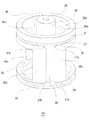
以下に、本発明の第1の実施の形態に係るロータリソレノイドを図面に基づいて説明する。図1は、本発明の第1の実施例に係るロータリソレノイドの分解斜視図である。図1において、10はロータリソレノイド、20はコイルボビン、21は上部枠、22a及び22bは縦枠、23は下部枠、24はシャフト固着部、25はビス穴、26a及び26bはガイド孔、27は上部周回溝、28aは縦溝、29は下部周回溝、40は構造支持体、41は内部固定磁極、42a及び42bは支持部、43はエンドキャップ部、44は貫通孔、45a及び45bはストッパ嵌合孔、46はベアリング嵌合孔、47及び48は内周面、49は段差面、50a及び50bは永久磁石、51はケース、52は開口部、53はエンドキャップ、54a及び54bは端子孔、55a及び55bは端子、56は保護板、57は開口部、58a及び58bは端子孔、60はコイル、61は上部線条、62a及び62bは縦線条、63は下部線条、64はビス、65及び66はワッシャ、67及び68はボールベアリング、69はフレキシブル配線板、70はシャフト、71は基端部、72は中間部、73は先端部、74はビス穴、75a及び75bはストッパである。また、図2は、本発明の第1の実施例に係るロータリソレノイドを示す斜視図であり、(a)は端子側の斜視図、(b)はシャフト先端側の斜視図である。図2の各符号は、全て図1と同じものを示す。なお、コイル60については、図1及び図2を初めとする各図面において、線条を繰り返し巻回した細かい態様の記載を省略し、総体的な外観形状によって表現している。
[First Embodiment]
Below, the rotary solenoid which concerns on the 1st Embodiment of this invention is demonstrated based on drawing. FIG. 1 is an exploded perspective view of a rotary solenoid according to a first embodiment of the present invention. In FIG. 1, 10 is a rotary solenoid, 20 is a coil bobbin, 21 is an upper frame, 22a and 22b are vertical frames, 23 is a lower frame, 24 is a shaft fixing portion, 25 is a screw hole, 26a and 26b are guide holes, and 27 is Upper circumferential groove, 28a is a longitudinal groove, 29 is a lower circumferential groove, 40 is a structure support, 41 is an internal fixed magnetic pole, 42a and 42b are support parts, 43 is an end cap part, 44 is a through hole, 45a and 45b are stoppers Fitting hole, 46 is a bearing fitting hole, 47 and 48 are inner peripheral surfaces, 49 is a stepped surface, 50a and 50b are permanent magnets, 51 is a case, 52 is an opening, 53 is an end cap, 54a and 54b are terminals Holes 55a and 55b are terminals, 56 is a protective plate, 57 is an opening, 58a and 58b are terminal holes, 60 is a coil, 61 is an upper wire, 62a and 62b are vertical wires, and 63 is a wire Partial wire strips, 64 screws, 65 and 66 washers, 67 and 68 ball bearings, 69 a flexible wiring board, 70 a shaft, 71 a proximal end portion, 72 an intermediate portion, 73 a distal end portion, and 74 a screw The holes 75a and 75b are stoppers. FIG. 2 is a perspective view showing a rotary solenoid according to the first embodiment of the present invention, in which (a) is a perspective view of a terminal side and (b) is a perspective view of a shaft front end side. 2 denote the same components as those in FIG. In addition, about the
図2に示すように、ロータリソレノイド10は、内部構造が略円筒形状のケース51に収納されており、(a)に示しているケース51の端面には端子55a及び55bが、(b)に示している端面にはシャフト70が突出している。ロータリソレノイド10の内部構造は、大別すると図1に示すように、内部構造を支持する台となる構造支持体40と、構造支持体40に対して一体的に設けた内部固定磁極41、シャフト70、ストッパ75a及び75bと、内部固定磁極41の外周面に貼り付けた永久磁石50a及び50bと、これらを覆うように設けたコイルボビン20と、コイルボビンの外周面に巻回したコイル60と、さらにこれらを覆うように設けたケース51を備えている。
As shown in FIG. 2, the
以下にロータリソレノイド10の細部の構造等について、図1に基づいて詳細に説明する。構造支持体40は、支持部42a及び42bと、エンドキャップ部43で構成される。支持部42a及び42bは、エンドキャップ部43から端子55a及び55bに向かって立ち上がるように形成されており、外周面は凸状円弧面、内周面は平坦面となっている。また、これら支持部の内周面同士は正対しており、かつ、エンドキャップ部43の中心がこれらの中間となるように配置されている。また、これらの内周面同士は、内部固定磁極41を間に嵌合するために好適な間隔に設定されている。さらに、支持部42a及び42bの頂部(シャフト70の基端側)には、ストッパ75a及び75bを嵌合して固着するためのストッパ嵌合孔45a及び45bが形成されている。なお、この実施の形態では、構造支持体40の材料として、磁性材料と非磁性材料とのいずれを用いることもできる。
The detailed structure of the
ストッパ75a及び75bは、先端側が。エンドキャップ部43は、略円盤形状に形成され、縁辺及びその近傍が肉薄になるような段差が形成されており、支持部42a及び42bは中心寄りの肉厚の部分から立ち上がっている。また、中心及びその近傍をベアリング嵌合孔46としており、ベアリング嵌合孔46にはボールベアリング68が嵌合される。
The
さらに、図3(b)に示すように、ベアリング嵌合孔46の内周面48には、ボールベアリング68の厚みに相当する高さの位置に、シャフト70の基端側(上側)が縮径するような段差を形成している。したがって、ボールベアリング68をベアリング嵌合孔46に圧入するときに、ボールベアリング68がこの段差に当接したところで圧入を止めることができるので、ボールベアリング68を過剰に押し込むことを防止できる。また、構造支持体40の肉薄の部分と肉厚の部分との段差面49は、コイルボビン20の下部枠23との間にわずかな間隙を持つように形成されている。段差面49とコイルボビン20の下部枠23と間隙は、非常に小さくなるよう設定されている。したがって、コイルボビン20の回転時に、何らかの要因によってコイルボビン20の下部枠23側が揺動する、つまり、コマが首を振りながら回転するのと同様の状態になると、下部枠23の内周面36が段差面49に接触することによって下部枠23の揺動を抑制する。
Further, as shown in FIG. 3B, the base end side (upper side) of the
コイルボビン20は、図1に示すように、下部枠23から縦枠22a及び22bが立ち上がるように形成され、さらに縦枠22a及び22bの頂部(シャフト70の基端側)に上部枠21が形成されている。下部枠23及び上部枠21は、コイルワイヤとも呼ばれる銅の線条を巻回するために円環形状に形成されている。縦枠22a及び22bは、シャフト70が介在するように配置され、シャフト70の中心軸が中間位置となる。
As shown in FIG. 1, the
コイルボビン20について、図3及び図5に基づいてさらに詳細に説明する。図3は、本発明の第1の実施例に係るロータリソレノイドの断面説明図(1)であり、(a)は正面図、(b)はA−A線断面図、(c)はB−B線断面図である。図3において、28bは縦溝、30は凹部、34a及び34bは縦枠、39は内周面、59は凹部、62bは縦線条であり、他の符号は図1と同じものを示す。また、図5は、第1の実施の形態に係るコイルボビンを示す斜視図である。図5において、30は凹部、31a及び31bは切欠、32aは貫通孔、33はテーパ部、35は天板部、36は内周面、37a及び37bは切欠である。
The
図3(b)に示すように、コイルボビン20は、樹脂からなり、上部枠21の下側に蓋状の天板部35が形成されており、上部枠21の内周面39と天板部35の上面とによって図5に示す凹部30を構成している。凹部30は、後述するように、端子55a及び55bとコイル60を構成する線条との接続手段であるフレキシブル配線板69を収納するための空間となっている。また、凹部30の中央には、シャフト固着部24が上部枠21よりもエンドキャップ53側に突出するように形成されている。これは、シャフト固着部24をエンドキャップ53に向かって長く延ばすことによって、シャフト70とコイルボビン20とが固着されている部分の面積が大きくなり、両者の固着状態をより強固なものにできることによる。
As shown in FIG. 3 (b), the
さらに、シャフト固着部24は、その中央にビス穴25が形成されている。シャフト70は、先端部73側をシャフト固着部24に挿入した状態でビス64とワッシャ65及び66によって固着されており、コイルボビン20とシャフト70とは一体的に設けられている。したがって、コイルボビン20が回転すると、これにつれてシャフト70も回転する。また、天板部35には、ガイド孔26a及び26bが形成されている。ガイド孔26a及び26bは、略円弧状になされたスリットであり、天板部35の中心、すなわちシャフト70の中心軸に対して点対称となるような位置及び形状になされている。前述したストッパ75a及び75bは、先端側がガイド孔26a及び26bに挿入されている。したがって、コイルボビン20の回転は、ストッパ75aとストッパ75bとの先端側がガイド孔26aとガイド孔26bの縁辺にそれぞれ当接したところで規制されることになる。したがって、ロータリソレノイド10において得られるシャフト70の回転角は、ガイド孔26a及び26bの長さに応じて、おおむね10度以上から180度弱の範囲で任意に設定できる。
Further, the
また、図5に示している下部枠23の内周面36は、図3(b)に示すように、構造支持体40の段差面49にきわめて近接しているが、内周面36と段差面49とが常時接触してコイルボビン20の回転を妨げることのない程度の公差を設定している。したがって、前述したように、コイルボビン20が安定的に回転しているときは内周面36と段差面49とが接触することはないが、回転中にコイルボビン20の下部枠23側が揺動したときには、段差面49との接触によって揺動が抑えられるので、シャフト70のトルクが安定する利点がある。なお、図3(b)に示すように、コイルボビン20の天板部35の下面は、内部固定磁極41及びボールベアリング67の上面にかなり近接しているが、これらについても常時接触してコイルボビン20の回転を妨げることのないような公差としている。
Further, as shown in FIG. 3B, the inner
コイルボビン20の上部枠21及び下部枠23には、図5に示すように、これらの周方向にそれぞれ上部周回溝27と下部周回溝29とを形成している。さらに、縦枠22a及び22bに縦溝28を形成し、縦枠34a及び34bにも図示していない縦溝を形成している。これらの溝を形成することによって、コイルボビン20に線条を巻き付ける際に、所定の部位をはずれて巻き付けることを防止できるようにしている。さらに、上部周回溝27の下側には、テーパ面33を形成している。テーパ面33は、上部周回溝27の端部近傍に巻回している線状が上部周回溝27の縁辺に掛かったときに、その線条がテーパ面33を滑り降りて上部周回溝27に収まるようにするために形成している。なお、このようなテーパ面は、図示していないが下部周回溝29側にも形成している。さらに、縦溝28と上部周回溝27とを接続している部分と、縦溝28と下部周回溝29とを接続している部分との角部に切欠31a及び31bと、切欠37a及び37bとをそれぞれ形成している。これらの切欠も線条を巻き付けやすくするために形成している。なお、図示していないが、縦枠34a及び34bにも同様の切欠を形成している。
As shown in FIG. 5, an upper
コイル60は、図1に示すように、コイルボビン20の構成、すなわち上部枠21、縦枠22a及び22b、並びに下部枠23に対応して、金属の線条を巻回し、上部線条61、縦線条62a及び62b、並びに下部線条63からなる構成としている。この実施の形態では、図5に示している上部枠21に形成した貫通孔32aの内周面39側から挿入した線条を、まず上部周回溝27を通って縦溝28を下向きに通し、下部周回溝20を半周した後、さらに縦溝28と反対側の縦溝を上向きに通し、次に上部周回溝27の貫通孔32aがない側を半周した後、再び縦溝28を下向きに通し、次に下部周回溝20の先に通さなかった側を半周した後、さらに縦溝28と反対側の縦溝を上向きに通し、次に上部周回溝27の貫通孔32aがある側を半周し、以降これを繰り返すように巻回することによってコイル60を形成している。
As shown in FIG. 1, the
コイル60の通電時には、縦線条62aを流れる電流と縦線条62bを流れる電流とは、上下逆方向となる。なお、線条を巻回する順序はこれの例に限られるものではないが、コイルボビン20の回転時における揺動を防止するために、下部周回溝20の片側ともう一方の側に巻回する巻数は同じ回数とすることが好ましい。また、コイル60の材料は銅に限られるものではなく、コイルの形成に好適な金属はいずれのものでも採用できる。さらに、図3(c)はコイル60の非通電時の状態を示しているが、この図に示すようにコイル60の非通電時には、縦線条62a及び62bは永久磁石50a及び50bの端部付近に位置している。このように配置することによって、コイル60の通電時にコイルボビン20の回転角を大きくすることが可能になる。
When the
内部固定磁極41は、磁性材料からなり、図1及び図3(b)に示すように筒状に形成されている。また、構造支持体40の支持部42a及び42bとの間に嵌合されており、さらに接着剤で構造支持体40に固着されている。さらに、支持部42a及び42bに覆われていない側面には、永久磁石50a及び50bが接着剤によって固着されている。くわえて、貫通孔44の上側開口には、ボールベアリング67が嵌合されている。なお、上側開口の内周面47には、ボールベアリング67の厚みに相当する深さの位置に、シャフト70の先端側(下側)が縮径するような段差を形成している。したがって、ボールベアリング67を貫通孔44に圧入するときに、ボールベアリング67がこの段差に当接したところで圧入を止めることができるので、ボールベアリング67を過剰に押し込むことを防止できる。
The internal fixed
永久磁石50a及び50bは、内側面が凹状円弧面に、外側面が凸状円弧面にそれぞれ形成され、かつ、内側面の曲率中心と外側面の曲率中心とがシャフト70の中心軸と一致している。また、図3(b)及び図4(b)から分かるように、永久磁石50a及び50bはコイルボビン20と内部固定磁極41との間の円筒形状の狭い空間内に設けられており、永久磁石50a及び50bとコイル60の縦線条62a及び62bとの間隙は非常に小さい。さらに、永久磁石50a及び50bの外周面は、上下方向の全幅に渡って縦線条62a及び62bに面している。したがって、この実施の形態においては、永久磁石50a及び50bの外周面全体がトルクの生成に寄与していると言える。
The
永久磁石50aは、シャフト70に対向している内周面側がN極、外周面側がS極となるように着磁されている。また、永久磁石及び50bは、シャフト70に対向している内周面側がS極、外周面側がN極となるように着磁されている。なお、これらの着磁方向は、シャフト70の中心軸を中心として扇状に広がるように方向付けられていることが好ましい。すなわち、扇状に着磁した場合、ロータリソレノイド10を平面視したときに、永久磁石50a及び50bの磁力線の方向は、内側面又は外側面の任意の部位の接線に対して直交する方向となる。コイル60を構成する各線条は、コイルボビン20が回転しているときに仮想的円弧面を描くように移動するので、永久磁石50a及び50bの磁力線の方向は、この仮想的円弧面とも直交することになる。つまり、コイル60の各線条を仮想的円弧面の接線方向に動かす力は、永久磁石50a及び50bをこのように着磁すると最も大きくなる。言い換えれば、最も効率的にトルクを得ることが可能な着磁形態となる。なお、永久磁石50a及び50bは、それぞれ図10と逆方向に着磁されていてもよい。
The
ケース51は、図1に示すように、略円筒形状に形成され、その両端部を閉止する蓋として、エンドキャップ53と、構造支持体40のエンドキャップ部43とが嵌合されている。また、ケース51は磁性材料からなり、後述するように、コイル60への通電時に、内部固定磁極41、並びに永久磁石50a及び50bと共に磁気回路を構成する。したがって、ケース51は、ロータリソレノイド10の内部機構を保護する機能と、外部固定磁極としての機能を併せ持っている。エンドキャップ53は、略円盤形状に形成され、縁辺及びその近傍が肉薄になるような段差が形成されており、この段差部がケース51の開口部52に嵌合される。また、エンドキャップ53の肉厚の部分には、端子55a及び55bを外部へ導出するために、端子孔54a及び54bが形成されている。さらに、図3(b)に示すように、エンドキャップ53は、ビス64の頭部がエンドキャップ53に当接してコイルボビン20及びシャフト70の回転を妨げることを防止するために、その下面に凹部59が形成されている。
As shown in FIG. 1, the
保護板56は、絶縁性材料によって略円盤形状に形成されており、中央には開口部57が形成され、さらに端子55a及び55bを配線する位置に端子孔58a及び58bが形成されている。開口部57は、図3(b)に示すように、コイルボビン20のシャフト固着部24が保護板56に接触してシャフト70及びコイルボビン20の回転を妨げることを防止するために形成されている。端子孔58a及び58bは、それぞれ端子55a及び55bを挿通するために形成されており、保護板56は挿通した端子55a及び55bによって保持されている。後述するように、フレキシブル配線板69は、その一部がコイルボビン20の回転に伴って動く。端子55a及び55bとフレキシブル配線板69との間に何もないと、ロータリソレノイド10を長期間使用するうちにフレキシブル配線板69が製造当初とは異なる状態に変形し、それに伴って端子55a及び55bまでも変形し、ねじれや接触による絶縁不良、断線などを起こすことが考えられる。そこで、保護板56を設けることによって端子55a及び55bの変形を防止している。なお、保護板56の移動を防止するために、保護板56の縁辺のいずれかに舌状の突出部を形成し、この突出部をケース51の内周面に接着してもよい。さらに、保護板56に代えて同形状のリジッド配線板を設け、このリジッド配線板にダイオードや磁気センサなど設けてもよい。
The
図4は、本発明の第1の実施例に係るロータリソレノイドの断面説明図(2)であり、(a)は側面図、(b)はC−C線断面図である。図4において、32bは貫通孔であり、その他の符号は、図1及び図3と同じものを示す。フレキシブル配線板69は、帯状に形成されおり、コイルボビン20の凹部30に収納されている。また、フレキシブル配線板69の一端部の接続ランドには、図5及び図4(b)に示したコイルボビン20の貫通孔32a及び32bを介して内周面39側に引き入れたコイル60の線条の端部を半田付けしている(半田付け部分は記載を省略している)。さらに、図示していないが、フレキシブル配線板69の他端部の接続ランドには、端子55a及び55bの先端部が半田付けされている。両端部の接続ランドの間の部分は、コイルボビン20の内周面39にほぼ沿った状態で配置されているが、端子55a及び55bの近傍部分は、端子55a及び55を螺旋状に取り巻くように配置されている。したがって、コイルボビン20の回転時には、コイル60を構成する線条に接続された側が回転につれて移動するが、端子55a及び55bの近傍部分が螺旋状の遊びとなっているので、端子55a及び55bに対して強い張力が働くことはない。
4A and 4B are cross-sectional explanatory views (2) of the rotary solenoid according to the first embodiment of the present invention, in which FIG. 4A is a side view and FIG. 4B is a cross-sectional view taken along the line CC. In FIG. 4, 32b is a through-hole, and other code | symbol shows the same thing as FIG.1 and FIG.3. The
シャフト70は、先端部73、中間部72、基端部71の順に段階的に縮径している。さらに、シャフト70は、中間部72がボールベアリング68を介して構造支持体40に、ボールベアリング67を介して内部固定磁極41に左右に回転自在な状態で支持されている。さらに、前述のように、シャフト70の先端部にはビス穴74が形成されており、シャフト70はビス64とワッシャ65及び66によってコイルボビン20と固着されている。したがって、シャフト70は、軸受となる二つのボールベアリングによって強固に支持されているので、先端部73にコイルボビン20を接続していても、コイルボビン20の慣性モーメントによる回転むらや揺動などを低減することができる。本実施の形態におけるシャフト70は、磁性、非磁性いずれの材料であっても動作する。なお、特に大きなトルクを必要とする場合などにおいては、磁性材料を用いることが好ましく、電磁ステンレスが特に好ましい。
The
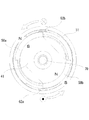
次に、本発明の第1の実施の形態に係るロータリソレノイド10の動作について説明する。図8は、本発明の第1の実施の形態に係るロータリソレノイドの動作を示す斜視図(1)である。また、図9は、本発明の第1の実施の形態に係るロータリソレノイドの動作を示す斜視図(2)である。さらに、図10は、通電方向と回転方向との関係を示す断面図である。図8、図9及び図10において用いた符号は、図1、図3及び図4と同じものを示す。なお、図10においては、ハッチングを省略している。
Next, the operation of the
図8は、図3及び図4に相当する。すなわち、コイル60の縦線条62aと縦線条62bとは、それぞれ永久磁石50aと永久磁石50bの側端近傍に位置している。また、ストッパ75aとストッパ75bとの先端側は、コイルボビン20のガイド孔26aとガイド孔26bとの縁辺にそれぞれ当接している。ここで、コイル60へ通電し、縦線条62と縦線条62bとに図10に示す方向に電流が流れると、永久磁石50a及び50bの近傍に荷電粒子の流れができ、この荷電粒子に流れに対するローレンツ力が発生する。
FIG. 8 corresponds to FIG. 3 and FIG. That is, the
そうすると、図10に示すように、コイル60に対する左回りの力が働いて、縦線条62aが永久磁石50bの外周側を通り抜けて永久磁石50aへ向かい、縦線条62bが永久磁石50aの外周側を通り抜けて永久磁石50bへ向ように回転する。このとき、シャフト70もコイルボビン20と一体的に回転する。また、フレキシブル配線板69のコイル60を半田付けした側の端部も同様に回転するが、端子55a及び55bの近傍に螺旋状の遊びを設けているので、端子55a及び55bに対して強い張力が働くことはない。コイルボビン20が図9に示している所定角度まで回転すると、ストッパ75aとストッパ75bとの先端側がコイルボビン20のガイド孔26aとガイド孔26bとの反対側の縁辺にそれぞれ当接するので、コイルボビン20の回転は停止する。
Then, as shown in FIG. 10, a counterclockwise force is applied to the
コイルボビン20が回転し切った状態において、図10とは逆方向に電流を流すと、コイルボビン20を上記とは反対方向に動かすローレンツ力が働くので、コイルボビン20には右回りの力が働く。したがって、コイルボビン20は、図8に示した元の位置、すなわちストッパ75aとストッパ75bとの先端側がコイルボビン20のガイド孔26aとガイド孔26bとの縁辺にそれぞれ当接する角度(方向)まで逆回転する。
In the state where the
なお、コイルボビン20を逆回転させるときに、逆方向に電流を流す手段以外の手段を採用してもよい。例えば、ケース51の内部又は外部に設けた弦巻バネなどの手段をシャフト70及びコイルボビン20を逆回転されるような状態に設けてもよい。このようにすれば、コイルボビン20が図9に示す角度まで回転したところでコイル60への通電を止めると、弦巻バネなどの手段の働きによってコイルボビン20が元の角度に戻るように動作するようになる。
Note that when the
以上説明したように、第1の実施の形態に係るロータリソレノイド10においては、シャフト70と一体的に回転する構成とすると共に、略円筒状のコイルボビン20の内側に永久磁石50a及び50bを配置し、かつ、永久磁石50a及び50bとコイル60の縦線条62a及び縦線条62bとをごく狭い間隙で対向させ、さらに、磁気回路を永久磁石50a及び50b、ケース51及び内部固定磁極41だけで構成するようにしたので、周辺空間への磁束漏れが少なくなり、発生した磁束を効率的にトルクに変換することができる。くわえて、コイルボビン20の内部空間に内部固定磁極41などの構成要素を配置している上に、ケース51の内部に大きな間隙を設ける必要がない。したがって、ロータリソレノイドの小型化を図る上で極めて好適な構成である。また、内部固定磁極41などの固定的な構成要素と、コイルボビン20などの可動的な構成要素との間にボールベアリング67及び68を設けているので、摩擦抵抗によるトルクの減衰を低減することが可能となる。さらに、ボールベアリング67及び68によって強固に保持されたシャフト70に対してコイルボビン20を固着しているので、コイルボビン20が回転中に周辺物に接触してトルクが減衰することを低減できる。また、コイルボビン20及びコイル60の構成をシャフト70の中心軸に対して点対称となるように配置しているので、質量が特定の一点に集中するなどアンバランスな構成になることがない。よって、コイルボビン20の回転中に、アンバランスな構成に起因するコイルボビン20の揺動を低減することが可能となる。したがって、ロータリソレノイド10は、小型化が容易であり、同時に高トルクを得るのに好適な構造を持っている。
As described above, the
[第2の実施の形態]
以下に、本発明の第2の実施の形態に係るロータリソレノイドを図面に基づいて詳細に説明する。図6は、本発明の第2の実施例に係るロータリソレノイドのコイルボビンを示す斜視図である。図6において、38はスリットであり、その他の符号は図5と同じものを示す。また、図7は、本発明の第2の実施例に係るロータリソレノイドを示す横断面図である。図7において用いた符号は、図3と同じものを示す。
[Second Embodiment]
Hereinafter, a rotary solenoid according to a second embodiment of the present invention will be described in detail with reference to the drawings. FIG. 6 is a perspective view showing a coil bobbin of a rotary solenoid according to the second embodiment of the present invention. In FIG. 6,
第2の実施の形態に係るロータリソレノイド10は、コイルボビン20の縦枠22aと縦枠22bとの間を縦溝28とするのではなく、スリット38としている。縦枠34aと縦枠34bについても同様の構成としている。したがって、この実施の形態においては、コイル60の縦線条62aと縦線条62bとが永久磁石50aと永久磁石50bとに対してむき出しの状態で対向している。その他の構成は、第1の実施の形態に係るロータリソレノイド10と同じである。したがって、この実施の形態においては、コイル60の巻数がさほど多くなく、永久磁石50a及び永久磁石50b側に線条が膨出する可能性が低いロータリソレノイドに好適である。
The
以上のように、第2の実施の形態に係るロータリソレノイド10においては、コイル60の縦線条62aと縦線条62bとが永久磁石50aと永久磁石50bとの間にごく狭い空間のみが介在する構造としたので、これらの間隙を極限まで狭めることができ、さらに磁束漏れを低減することができる。したがって、第1の実施の形態に係るロータリソレノイド10と同様に小型化することが可能になると共に、より大きなトルクを得ることができる。
As described above, in the
[第3の実施の形態]
以下に、本発明の第3の実施の形態に係るロータリソレノイドを図面に基づいて詳細に説明する。図11は、本発明の第3の実施例に係るロータリソレノイドの永久磁石とその周辺構造を示す斜視図である。図11において、50は永久磁石であり、その他の符号は図1と同様である。また、図12は、通電方向と回転方向との関係を示す断面図である。図12において用いた符号は、図1及び図11と同じものを示す。なお、図12においては、ハッチングを省略している。
[Third Embodiment]
Hereinafter, a rotary solenoid according to a third embodiment of the present invention will be described in detail with reference to the drawings. FIG. 11 is a perspective view showing a permanent magnet and its peripheral structure of a rotary solenoid according to a third embodiment of the present invention. In FIG. 11, 50 is a permanent magnet, and other symbols are the same as those in FIG. FIG. 12 is a cross-sectional view showing the relationship between the energization direction and the rotation direction. The reference numerals used in FIG. 12 are the same as those in FIGS. In FIG. 12, hatching is omitted.
第3の実施の形態に係るロータリソレノイド10は、第1の実施の形態の永久磁石50a及び50bに代えて永久磁石50を設けている。すなわち、永久磁石50は、底部のない略円筒形状に形成され、縦枠22aと縦枠22bとの間に嵌合される。さらに縦枠22a及び縦枠22bの外周面と永久磁石の内周面とは接着されている。永久磁石50の厚みは、図1の永久磁石50a及び50bと同じであり、コイルボビン20との間にわずかな間隙を設けている。また、図12に示すように、永久磁石50は、縦線条62aの近傍の部分がN極、縦線条62bの近傍の部分がS極となるように着磁されている。その他の部分の構成は、すべて第1の実施の形態と同じである。したがって、コイル60へ通電すると、永久磁石50の外周側が永久磁石50a及び50bと同様の極性を持つことから、第1の実施の形態と同様に図12の矢印の方向に回転する。
The
この実施の形態においては、永久磁石の容積は大きくなるが、その分より大きなトルクを得られるという利点がある。なお、この実施の形態においては、永久磁石50と支持部42a及び42bとを短絡する不要な磁気回路の生成を防止するために、構造支持体40は非磁性材料で形成することが非常に望ましい。
In this embodiment, the volume of the permanent magnet increases, but there is an advantage that a larger torque can be obtained. In this embodiment, in order to prevent generation of an unnecessary magnetic circuit that short-circuits the
[第4の実施の形態]
以下に、本発明の第4の実施の形態に係るロータリソレノイドを図面に基づいて詳細に説明する。図13は、本発明の第3の実施例に係るロータリソレノイドの永久磁石とその周辺構造を示す斜視図である。また、図14は、通電方向と回転方向との関係を示す断面図である。図13及び図14において用いた符号は、図11及び図12と同じものを示す。なお、図14においては、ハッチングを省略している。
[Fourth Embodiment]
Hereinafter, a rotary solenoid according to a fourth embodiment of the present invention will be described in detail with reference to the drawings. FIG. 13 is a perspective view showing a permanent magnet of a rotary solenoid and its peripheral structure according to a third embodiment of the present invention. FIG. 14 is a cross-sectional view showing the relationship between the energization direction and the rotation direction. The reference numerals used in FIGS. 13 and 14 are the same as those in FIGS. 11 and 12. In FIG. 14, hatching is omitted.
第4の実施の形態に係るロータリソレノイド10は、第1の実施の形態の固定内部磁極41と永久磁石50a及び50bとに代えて永久磁石50を設けている。すなわち、永久磁石50は、第1の実施の形態における固定内部磁極41と永久磁石50a及び50bとを合わせた形状に形成され、支持部42aと支持部42bとの間に嵌合されている。また、図14に示すように、永久磁石50は、縦線条62aの近傍の部分がN極、縦線条62bの近傍の部分がS極となるように着磁されている。その他の部分の構成は、すべて第1の実施の形態と同じである。したがって、コイル60へ通電すると、永久磁石50の外周側が永久磁石50a及び50bと同様の極性を持ち、永久磁石50が内部固定磁極としての作用も発揮するので、第1の実施の形態と同様に図14の矢印の方向に回転する。
The
この実施の形態においては、永久磁石の容積は大きくなり、さらに縦枠22aと縦枠22bとの間に嵌合するときに亀裂や欠けを生じない材料を選択する必要があるが、その分より大きなトルクを得られるという利点がある。なお、この実施の形態においては、永久磁石50と支持部42a及び42bとを短絡する不要な磁気回路の生成を防止するために、構造支持体40は非磁性材料で形成することが非常に望ましい。
In this embodiment, the volume of the permanent magnet is increased, and it is necessary to select a material that does not crack or chip when fitted between the
なお、本発明は以上に説明した内容に限定されるものではなく、コイルボビン、ケース、エンドキャップ又は構造支持体の細部の形状や、コイルボビンへの金属の線条の巻回順序などについては、各請求項に記載した範囲を逸脱しない限りにおいて種々の変形を加えることが可能である。また、各実施の形態に係るロータリソレノイドの構成を説明する際に述べた各部の変形例は、他の実施の形態に係るロータリソレノイドにおいても、構造的な矛盾を生じない限りにおいて好ましく適用できる。 The present invention is not limited to the above-described contents, and details of the shape of the coil bobbin, case, end cap or structural support, and the winding order of the metal filaments on the coil bobbin, etc. Various modifications can be made without departing from the scope of the claims. In addition, the modification of each part described when describing the configuration of the rotary solenoid according to each embodiment can be preferably applied to the rotary solenoids according to other embodiments as long as no structural contradiction occurs.
10 ロータリソレノイド
20 コイルボビン
21 上部枠
22a 縦枠
22b 縦枠
23 下部枠
24 シャフト固着部
25 ビス穴
26a ガイド孔
26b ガイド孔
27 上部周回溝
28 縦溝
29 下部周回溝
30 凹部
31a 切欠
31b 切欠
32a 貫通孔
32b 貫通孔
33 テーパ面
34a 縦枠
34b 縦枠
35 天板部
36 内周面
37a 切欠
37b 切欠
38 スリット
39 内周面
40 構造支持体
41 内部固定磁極
42a 支持部
42b 支持部
43 エンドキャップ部
44 貫通孔
45a ストッパ嵌合孔
45b ストッパ嵌合孔
46 ベアリング嵌合孔
47 内周面
48 内周面
49 段差面
50 永久磁石
50a 永久磁石
50b 永久磁石
51 ケース
52 開口部
53 エンドキャップ
54a 端子孔
54b 端子孔
55a 端子
55b 端子
56 保護板
57 開口部
58a 端子孔
58b 端子孔
59 凹部
60 コイル
61 上部線条
62 縦線条
62a 縦線条
62b 縦線条
63 下部線条
64 ビス
65 ワッシャ
66 ワッシャ
67 ボールベアリング
68 ボールベアリング
69 フレキシブル配線板
70 シャフト
71 基端部
72 中間部
73 先端部
74 ビス穴
75a ストッパ
75b ストッパ
10
Claims (9)
前記コイルボビンの内部に配置された第1の永久磁石及び第2の永久磁石と、
前記コイルボビンに金属の線条を巻回して形成されたコイルと、
前記コイルボビンと一体的に設けられると共に、回転自在になされたシャフトとを有するロータリソレノイドにおいて、
前記コイルボビンは、外周面上に第1の縦溝及び第2の縦溝が互いに背向するように形成され、
前記第1の永久磁石は、前記コイルボビンの内周面の前記第1の縦溝に背向する部位の近傍に配置され、前記第2の永久磁石は、前記コイルボビンの内周面の前記第2の縦溝に背向する部位の近傍に配置されると共に、前記第1の永久磁石と前記第2の永久磁石との着磁方向が逆向きになされ、
前記コイルは、前記線条の一部が前記コイルボビンの前記第1の縦溝及び前記第2の縦溝の内部に配線されると共に、前記コイルへの通電時に前記第1の縦溝の内部に配線された部分を流れる電流と前記第2の縦溝の内部に配線された部分を流れる電流とが逆方向となることを特徴とするロータリソレノイド。 A coil bobbin formed in a substantially cylindrical shape;
A first permanent magnet and a second permanent magnet disposed inside the coil bobbin;
A coil formed by winding a metal wire around the coil bobbin;
In a rotary solenoid that is provided integrally with the coil bobbin and that has a rotatable shaft,
The coil bobbin is formed on the outer peripheral surface so that the first vertical groove and the second vertical groove face each other,
The first permanent magnet is disposed in the vicinity of a portion of the inner peripheral surface of the coil bobbin facing away from the first vertical groove, and the second permanent magnet is the second permanent magnet on the inner peripheral surface of the coil bobbin. And the magnetizing direction of the first permanent magnet and the second permanent magnet is opposite to each other.
In the coil, a part of the wire is wired inside the first vertical groove and the second vertical groove of the coil bobbin, and inside the first vertical groove when the coil is energized. A rotary solenoid characterized in that a current flowing through a wired portion and a current flowing through a portion wired inside the second vertical groove are in opposite directions.
略円筒形状に形成されると共に、前記コイルボビンの内部に配置された永久磁石と、
前記コイルボビンに金属の線条を巻回して形成されたコイルと、
前記コイルボビンと一体的に設けられると共に左右に回転自在になされたシャフトとを有するロータリソレノイドにおいて、
前記コイルボビンは、外周面上に第1の縦溝及び第2の縦溝が互いに背向するように形成され、
前記永久磁石は、第1の極性部が前記コイルボビンの内周面の前記第1の縦溝に背向する部位の近傍に配置され、第2の極性部が前記コイルボビンの内周面の前記第2の縦溝に背向する部位の近傍に配置され、
前記コイルは、前記線条の一部が前記コイルボビンの前記第1の縦溝及び前記第2の縦溝の内部に配線されると共に、前記コイルへの通電時に前記第1の縦溝の内部に配線された部分を流れる電流と前記第2の縦溝の内部に配線された部分を流れる電流とが上下逆方向となることを特徴とするロータリソレノイド。 A coil bobbin formed in a substantially cylindrical shape;
A permanent magnet formed in a substantially cylindrical shape and disposed inside the coil bobbin;
A coil formed by winding a metal wire around the coil bobbin;
In a rotary solenoid having a shaft that is provided integrally with the coil bobbin and that is rotatable to the left and right,
The coil bobbin is formed on the outer peripheral surface so that the first vertical groove and the second vertical groove face each other,
The permanent magnet is disposed in the vicinity of a portion where the first polar portion faces away from the first vertical groove on the inner peripheral surface of the coil bobbin, and the second polar portion is disposed on the inner peripheral surface of the coil bobbin. It is arranged in the vicinity of the part facing away from the vertical groove of 2,
In the coil, a part of the wire is wired inside the first vertical groove and the second vertical groove of the coil bobbin, and inside the first vertical groove when the coil is energized. A rotary solenoid characterized in that a current flowing through a wired portion and a current flowing through a portion wired inside the second vertical groove are in opposite directions.
外周面を周回するように、かつ、前記第1の縦溝及び前記第2の縦溝の下端部に接続するように形成された下部周回溝とを備えていることを特徴とする請求項1から請求項4のいずれか一項に記載のロータリソレノイド。 The coil bobbin has an upper circumferential groove formed so as to circulate on an outer peripheral surface and to be connected to upper ends of the first vertical groove and the second vertical groove;
2. A lower circumferential groove formed so as to circulate around an outer peripheral surface and to be connected to lower ends of the first vertical groove and the second vertical groove. The rotary solenoid according to claim 1.
外周面を周回するように、かつ、前記第1のスリット及び前記第2のスリットの下端部に接続するように形成された下部周回溝とを備えていることを特徴とする請求項6に記載のロータリソレノイド。 The coil bobbin has an upper circumferential groove formed so as to circulate on an outer peripheral surface and to be connected to upper end portions of the first slit and the second slit;
The lower circumference groove formed so that it may go around an outer peripheral surface and may connect with the lower end part of the 1st slit and the 2nd slit, It is characterized by the above-mentioned. Rotary solenoid.
前記シャフトは、基端部が前記コイルボビンの前記底部に固着され、
略棒状に形成されると共に、先端側を前記コイルボビンの前記底部の前記スリットに挿入した状態で保持されたストッパをさらに有することを特徴とする請求項1から請求項7のいずれか一項に記載のロータリソレノイド。 The coil bobbin is formed in a bottomed cylindrical shape having a bottom on the base end side of the shaft, and a substantially arc-shaped slit is formed in the bottom.
The shaft has a proximal end fixed to the bottom of the coil bobbin,
8. The stopper according to claim 1, further comprising a stopper that is formed in a substantially rod shape and is held in a state in which a distal end side is inserted into the slit of the bottom portion of the coil bobbin. Rotary solenoid.
Priority Applications (1)
| Application Number | Priority Date | Filing Date | Title |
|---|---|---|---|
| JP2008331918A JP5114650B2 (en) | 2008-12-26 | 2008-12-26 | Rotary solenoid |
Applications Claiming Priority (1)
| Application Number | Priority Date | Filing Date | Title |
|---|---|---|---|
| JP2008331918A JP5114650B2 (en) | 2008-12-26 | 2008-12-26 | Rotary solenoid |
Publications (2)
| Publication Number | Publication Date |
|---|---|
| JP2010153686A JP2010153686A (en) | 2010-07-08 |
| JP5114650B2 true JP5114650B2 (en) | 2013-01-09 |
Family
ID=42572445
Family Applications (1)
| Application Number | Title | Priority Date | Filing Date |
|---|---|---|---|
| JP2008331918A Expired - Fee Related JP5114650B2 (en) | 2008-12-26 | 2008-12-26 | Rotary solenoid |
Country Status (1)
| Country | Link |
|---|---|
| JP (1) | JP5114650B2 (en) |
Family Cites Families (5)
| Publication number | Priority date | Publication date | Assignee | Title |
|---|---|---|---|---|
| JPS5910459U (en) * | 1982-07-12 | 1984-01-23 | 株式会社三協精機製作所 | lock actuator |
| JPS6063909U (en) * | 1983-10-07 | 1985-05-07 | 住友特殊金属株式会社 | rotary solenoid |
| JPH0356010Y2 (en) * | 1986-08-23 | 1991-12-16 | ||
| JPH0670530A (en) * | 1991-08-22 | 1994-03-11 | Hitachi Ltd | Rotary actuator |
| JPH07123680A (en) * | 1992-03-09 | 1995-05-12 | Shicoh Eng Co Ltd | Swing brushless actuator |
-
2008
- 2008-12-26 JP JP2008331918A patent/JP5114650B2/en not_active Expired - Fee Related
Also Published As
| Publication number | Publication date |
|---|---|
| JP2010153686A (en) | 2010-07-08 |
Similar Documents
| Publication | Publication Date | Title |
|---|---|---|
| US9077224B2 (en) | Rotor core, rotor, and rotating electric machine | |
| KR20200096414A (en) | Roter and motor | |
| JP7300525B2 (en) | axial gap motor | |
| CN103370860A (en) | Rotary solenoid | |
| KR100631190B1 (en) | PM type stepping motor with claw-pole | |
| JP2012070522A (en) | Spherical motor | |
| JP2010029017A (en) | Axial gap type rotary electric machine | |
| JP2006014578A (en) | Stepping motor | |
| US8907753B2 (en) | Rotary solenoid | |
| JPH044743A (en) | Rotary actuator | |
| JP6115448B2 (en) | Manufacturing method of rotor for rotating electrical machine and rotor for rotating electrical machine | |
| JP2010153686A (en) | Rotary solenoid | |
| JP2013121275A (en) | Linear actuator | |
| JP5418613B2 (en) | Field element and rotating electric machine | |
| JP5205663B2 (en) | Rotary solenoid | |
| JP5156927B2 (en) | Rotary solenoid | |
| JP2754296B2 (en) | Rotary actuator | |
| JP2022131772A (en) | motor | |
| JP5382791B2 (en) | Rotary solenoid | |
| JP5034069B2 (en) | Stepping motor | |
| JP2022131771A (en) | motor | |
| JP2007201207A (en) | Bobbin for coil and inductance element | |
| JP5339446B2 (en) | Rotary solenoid | |
| JP5317114B2 (en) | Rotary solenoid | |
| JP4541819B2 (en) | Torque motor |
Legal Events
| Date | Code | Title | Description |
|---|---|---|---|
| A621 | Written request for application examination |
Free format text: JAPANESE INTERMEDIATE CODE: A621 Effective date: 20111005 |
|
| A977 | Report on retrieval |
Free format text: JAPANESE INTERMEDIATE CODE: A971007 Effective date: 20120829 |
|
| TRDD | Decision of grant or rejection written | ||
| A01 | Written decision to grant a patent or to grant a registration (utility model) |
Free format text: JAPANESE INTERMEDIATE CODE: A01 Effective date: 20120904 |
|
| A01 | Written decision to grant a patent or to grant a registration (utility model) |
Free format text: JAPANESE INTERMEDIATE CODE: A01 |
|
| A61 | First payment of annual fees (during grant procedure) |
Free format text: JAPANESE INTERMEDIATE CODE: A61 Effective date: 20120913 |
|
| R150 | Certificate of patent or registration of utility model |
Ref document number: 5114650 Country of ref document: JP Free format text: JAPANESE INTERMEDIATE CODE: R150 Free format text: JAPANESE INTERMEDIATE CODE: R150 |
|
| FPAY | Renewal fee payment (event date is renewal date of database) |
Free format text: PAYMENT UNTIL: 20151026 Year of fee payment: 3 |
|
| R250 | Receipt of annual fees |
Free format text: JAPANESE INTERMEDIATE CODE: R250 |
|
| R250 | Receipt of annual fees |
Free format text: JAPANESE INTERMEDIATE CODE: R250 |
|
| LAPS | Cancellation because of no payment of annual fees |