JP5115219B2 - Magnetic separation device - Google Patents
Magnetic separation device Download PDFInfo
- Publication number
- JP5115219B2 JP5115219B2 JP2008019094A JP2008019094A JP5115219B2 JP 5115219 B2 JP5115219 B2 JP 5115219B2 JP 2008019094 A JP2008019094 A JP 2008019094A JP 2008019094 A JP2008019094 A JP 2008019094A JP 5115219 B2 JP5115219 B2 JP 5115219B2
- Authority
- JP
- Japan
- Prior art keywords
- magnetic
- raw water
- magnetic disk
- separation tank
- floc
- Prior art date
- Legal status (The legal status is an assumption and is not a legal conclusion. Google has not performed a legal analysis and makes no representation as to the accuracy of the status listed.)
- Expired - Fee Related
Links
Images


Classifications
-
- B—PERFORMING OPERATIONS; TRANSPORTING
- B03—SEPARATION OF SOLID MATERIALS USING LIQUIDS OR USING PNEUMATIC TABLES OR JIGS; MAGNETIC OR ELECTROSTATIC SEPARATION OF SOLID MATERIALS FROM SOLID MATERIALS OR FLUIDS; SEPARATION BY HIGH-VOLTAGE ELECTRIC FIELDS
- B03C—MAGNETIC OR ELECTROSTATIC SEPARATION OF SOLID MATERIALS FROM SOLID MATERIALS OR FLUIDS; SEPARATION BY HIGH-VOLTAGE ELECTRIC FIELDS
- B03C1/00—Magnetic separation
- B03C1/02—Magnetic separation acting directly on the substance being separated
Landscapes
- Separation Of Suspended Particles By Flocculating Agents (AREA)
- Water Treatment By Electricity Or Magnetism (AREA)
Description
本発明は磁気分離装置に係り、特に原水中の磁性フロックを磁気ディスクに吸着して原水中から分離除去する技術に関する。 The present invention relates to a magnetic separation device, and more particularly, to a technique for separating and removing magnetic flocs in raw water by attracting them to a magnetic disk.
下水や工場排水等の原水中に存在する汚濁物質を除去する装置として磁気分離装置がある。この磁気分離装置は、原水中に凝集剤と磁性粉を添加することにより、汚濁物質を磁性を帯びた磁性フロックとして形成し、この磁性フロックFを磁石を配設した磁気ディスクに吸着して分離除去するもので、マグシード法と呼ばれている。 There is a magnetic separation device as a device for removing pollutants present in raw water such as sewage and factory effluent. In this magnetic separation device, a flocculant and magnetic powder are added to raw water to form a pollutant as a magnetic floc with magnetism, and this magnetic floc F is attracted to a magnetic disk provided with a magnet and separated. What is removed is called the mug seed method.
特許文献1には、磁気分離装置を組み込んだ固液分離装置が開示されている。特許文献1に示すように、磁気分離装置は、分離槽内に、磁石を貼り付けた複数枚の磁気ディスクを回転軸に間隔を置いて配設したものであり、磁性フロックを磁気ディスクに吸着することで原水中から除去回収する。
しかしながら、従来の磁気分離装置は、原水中から磁性フロックを除去する性能が次の点で未だ充分とは言えない。 However, the conventional magnetic separation apparatus is still not sufficient in terms of the ability to remove magnetic floc from raw water in the following points.
(1)分離槽内に給水された原水は、複数枚の磁気ディスクに均等に接触することが原水中の磁性フロックを効率的に除去する上で重要である。しかし、従来の磁気分離装置は分離槽内の水流が偏り易い。 (1) In order to efficiently remove magnetic flocs in the raw water, it is important that the raw water supplied to the separation tank is in contact with a plurality of magnetic disks evenly. However, the conventional magnetic separation device tends to bias the water flow in the separation tank.
(2)磁性フロックを分離槽内の原水中に略半水没させた構成の場合、磁気ディスクに吸着した磁性フロックは原水中では剥離し易く、磁気ディスクの回転により原水中から大気中に搬送された時点では乾燥するので磁気ディスク面に固着して剥がれにくくなる。従来の磁気分離装置は、原水中において磁気ディスクに一旦吸着した磁性フロックが剥離してしまう問題に対する対策、吸着された磁性フロックを大気中にて効率的に回収するための対策が十分とは言えない。 (2) In the case where the magnetic floc is submerged substantially half-submerged in the raw water in the separation tank, the magnetic floc adsorbed on the magnetic disk is easy to peel off in the raw water and is transported from the raw water to the atmosphere by the rotation of the magnetic disk. Since it dries at the time, it adheres to the magnetic disk surface and is difficult to peel off. The conventional magnetic separation device has sufficient measures for the problem that the magnetic flocs once adsorbed to the magnetic disk in the raw water peel off, and the measures for efficiently recovering the adsorbed magnetic flocs in the atmosphere. Absent.
本発明はこのような事情に鑑みてなされたもので、従来の磁気分離装置がかかえる磁性フロックの吸着分離効率、及び回収効率の問題を解消し、原水中に含有する磁性フロックを高性能に除去することができる磁気分離装置を提供することを目的とする。 The present invention has been made in view of such circumstances, and solves the problem of the adsorption separation efficiency and recovery efficiency of the magnetic floc that the conventional magnetic separation apparatus has, and removes the magnetic floc contained in the raw water with high performance. An object of the present invention is to provide a magnetic separation device capable of performing the above.
請求項1に記載の発明は、前記目的を達成するために、磁性フロックを含有する原水が流入する分離槽と、前記分離槽内に配設された回転軸に所定間隔を有して並設され、前記磁性フロックを磁性力により吸着する複数枚の磁気ディスクと、吸着した磁性フロックを回収する回収手段と、を備えた磁気分離装置において、前記複数枚の磁気ディスクが前記分離槽の原水中に略半水没されるように配置され、前記分離槽の下端に形成された給水口から前記原水を分離槽内に上向流として給水すると共に、前記複数枚のそれぞれの磁気ディスクの真下には、前記給水口から給水された原水を前記磁気ディスク面の左右方向及び前記磁気ディスクの厚み方向に分流する分流部材が配設され、前記分離槽の前記回転軸と平行な両側には、前記磁気ディスクにより原水中の磁性フロックが除去された処理水が越流する一対のトラフが設けられ、前記分流部材は前記原水を分流し、各分流された原水を隣接する磁気ディスク間の間隙に流れ込むように案内することを特徴とする磁気分離装置を提供する。 In order to achieve the above object, the invention according to claim 1 is provided with a separation tank into which raw water containing magnetic floc flows and a rotating shaft disposed in the separation tank with a predetermined interval. A magnetic separation apparatus comprising: a plurality of magnetic disks that adsorb the magnetic flocs by magnetic force; and a recovery unit that collects the adsorbed magnetic flocs, wherein the plurality of magnetic disks are in the raw water of the separation tank. The raw water is supplied as an upward flow into the separation tank from a water supply port formed at the lower end of the separation tank, and is directly below each of the plurality of magnetic disks. A diversion member for diverting the raw water supplied from the water supply port in the left-right direction of the magnetic disk surface and the thickness direction of the magnetic disk is disposed on both sides of the separation tank parallel to the rotation axis. Di A pair of trough treated water magnetic flocs in the raw water are removed to the overflow is provided by click, the shunt member to flow into the gap between the magnetic disk adjacent the flowing said raw water min were each diverted raw water The magnetic separation device is characterized by being guided to the above.
請求項1によれば、分離槽の下端に形成した給水口から給水された原水は、分流部材に衝突して磁気ディスクの径方向左右と磁気ディスクの厚み方向に分流される。このように、給水口から給水された原水が分流部材に衝突して左右方向と磁気ディスクの厚み方向へ流れとして分流されることにより、磁気ディスク同士の間を流れる原水の流速が減速され、磁気ディスク同士の間をゆっくりとした上向流となって上昇する。これにより、原水中の磁性フロックを磁気ディスクに効率的に吸着することができる。 According to the first aspect of the present invention, the raw water supplied from the water supply port formed at the lower end of the separation tank collides with the flow dividing member and is divided in the radial direction of the magnetic disk and in the thickness direction of the magnetic disk. In this way, the raw water supplied from the water supply port collides with the flow dividing member and is divided as a flow in the left-right direction and the thickness direction of the magnetic disk, so that the flow rate of the raw water flowing between the magnetic disks is reduced, and the magnetic It rises as a slow upward flow between the disks. Thereby, the magnetic floc in raw water can be efficiently adsorbed to the magnetic disk.
また、分離槽の前記回転軸と平行な両側には、磁気ディスクにより原水中の磁性フロックが除去された処理水が越流する一対のトラフが設けられているので、分流した流れが分離槽内で滞留することなく、処理水を速やかに分離槽外に排出することができる。 In addition, a pair of troughs are provided on both sides parallel to the rotation axis of the separation tank so that the treated water from which the magnetic flocs in the raw water have been removed by the magnetic disk overflows. The treated water can be quickly discharged out of the separation tank without staying in the tank.
また、磁気ディスクの真下に分流部材を配置したことにより、原水が流速の速い上向流となって磁気ディスクの面近傍を流れることを防止できるので、磁気ディスクの面に一旦吸着した磁性フロックが剥離して原水中に脱落してしまうことがない。 In addition, by arranging the diversion member directly under the magnetic disk, it is possible to prevent the raw water from flowing near the surface of the magnetic disk as an upward flow with a high flow velocity. It will not peel off and fall into the raw water.
請求項2は請求項1において、前記分流部材は、上端面の厚みが前記磁気ディスクの厚みと同等に形成されると共に、下端にいくに従って厚みが薄くなる断面楔形状に形成されていることを特徴とする。 According to a second aspect of the present invention, in the first aspect, the flow dividing member is formed in a wedge shape having a cross-sectional wedge shape in which the thickness of the upper end surface is formed to be equal to the thickness of the magnetic disk and the thickness decreases toward the lower end. Features.
請求項2で規定したように分流部材の形状を形成することで、給水口から給水された原水を磁気ディスクの径方向左右と厚み方向に精度良く分流することができる。 By forming the shape of the diverting member as defined in claim 2, the raw water supplied from the water supply port can be accurately diverted in the radial direction left and right and the thickness direction of the magnetic disk.
請求項3は請求項1又は2において、前記給水口は、前記回転軸方向に長い四角筒形状に形成されていることを特徴とする。 A third aspect of the present invention is characterized in that, in the first or second aspect, the water supply port is formed in a rectangular tube shape that is long in the direction of the rotation axis.
請求項3で規定したように給水口を回転軸方向に長い四角筒形状に形成することで、分離槽内に均等に給水され易く、磁性フロックの除去性能を一層向上できる。 By forming the water supply port in a rectangular tube shape that is long in the direction of the rotation axis as defined in claim 3, it is easy to supply water evenly into the separation tank, and the magnetic floc removal performance can be further improved.
請求項4は請求項1〜3の何れか1において、前記複数枚のそれぞれの磁気ディスクの外周面と、前記分離槽の内面との間には、基端部が前記分離槽内面に固定され、先端部が自由端として前記磁気ディスクの外周面に接触されたシール板が配設されていることを特徴とする。 According to a fourth aspect of the present invention, in any one of the first to third aspects, a base end portion is fixed to the inner surface of the separation tank between the outer peripheral surface of each of the plurality of magnetic disks and the inner surface of the separation tank. In addition, a seal plate is provided in which the tip is in contact with the outer peripheral surface of the magnetic disk as a free end.
請求項4によれば、複数枚のそれぞれの磁気ディスクの外周面と、分離槽の内面との間にシール板を配設するようにしたので、磁気ディスクの外周面をショートパスして、磁気ディスクの面に接触せずにトラフに越流する流れを防止できるので、磁性フロックの除去性能を一層向上できる。 According to the fourth aspect of the present invention, the seal plate is disposed between the outer peripheral surface of each of the plurality of magnetic disks and the inner surface of the separation tank. Since the flow over the trough without contacting the disk surface can be prevented, the magnetic floc removal performance can be further improved.
請求項5は請求項1〜4の何れか1において、前記回収手段は、回転する磁気ディスクが大気中から原水中に進入する直前の磁気ディスク同士の間に、前記回転軸の近傍から前記分離槽の外部まで樋状に配設され、両側面上端のエッジ部分が磁気ディスク面に所定の付勢力を有して当接することにより、磁気ディスク面に吸着された磁性フロックを掻き取る樋状スクレーパと、樋状スクレーパ内に配設され、掻き取られて樋状スクレーパ内に落下堆積した磁性フロックを前記分離槽の外部まで搬送する搬送手段と、を備えたことを特徴とする。 According to a fifth aspect of the present invention, in the method according to any one of the first to fourth aspects, the recovery means may perform the separation from the vicinity of the rotating shaft between the magnetic disks immediately before the rotating magnetic disk enters the raw water from the atmosphere. A bowl-shaped scraper that is arranged in a bowl shape to the outside of the tank, and scrapes off the magnetic flocs adsorbed on the magnetic disk surface by the edges of the upper ends of both sides coming into contact with the magnetic disk surface with a predetermined urging force. And a conveying means that is disposed in the bowl-shaped scraper and is scraped off and deposited in the bowl-shaped scraper to the outside of the separation tank.
請求項5によれば、回転する磁気ディスクが大気中から原水中に進入する直前の磁気ディスク同士の間に、回転軸の近傍から分離槽の外部まで樋状に配設され、両側面上端のエッジ部分が磁気ディスク面に所定の付勢力を有して当接することにより、磁気ディスク面に吸着された磁性フロックを掻き取る樋状スクレーパを設けたので、大気中において乾燥して磁気ディスク面に固着した磁性フロックであっても、確実に掻き取ることができ、掻き取った磁性フロックを確実に樋状スクレーパ内に回収することができる。 According to the fifth aspect, the rotating magnetic disk is disposed in a bowl shape between the magnetic disks just before entering the raw water from the atmosphere, from the vicinity of the rotating shaft to the outside of the separation tank, Since the edge portion abuts against the magnetic disk surface with a predetermined urging force to provide a bowl-shaped scraper that scrapes off the magnetic flocs adsorbed on the magnetic disk surface, it is dried in the atmosphere and applied to the magnetic disk surface. Even the fixed magnetic floc can be surely scraped off, and the scraped magnetic floc can be reliably recovered in the bowl-shaped scraper.
以上説明したように、本発明に係る磁気分離装置によれば、従来の磁気分離装置がかかえる磁性フロックの吸着分離効率、及び回収効率の問題を解消し、原水中に含有する磁性フロックを高性能に除去することができる。 As described above, according to the magnetic separation apparatus of the present invention, the problem of the adsorption separation efficiency and the recovery efficiency of the magnetic floc that the conventional magnetic separation apparatus has solved is solved, and the magnetic floc contained in the raw water has a high performance. Can be removed.
以下、添付図面に従って本発明に係る磁気分離装置の好ましい実施の形態について詳説する。 Hereinafter, preferred embodiments of a magnetic separation device according to the present invention will be described in detail with reference to the accompanying drawings.
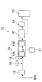
図1は、本発明の磁気分離装置20を、汚濁水浄化システム10に組み込んだフローを説明するブロック図である。また、図2は、汚濁水浄化システム10を構成する凝集装置14、磁気分離装置20、フィルター分離装置24の概念図である。
FIG. 1 is a block diagram for explaining a flow in which the
図1に示すように、汚濁水浄化システム10は、原水が原水ポンプ12によって先ず凝集装置14の急速攪拌槽14Aに送水される。また、原水ポンプ12と急速攪拌槽14Aとをつなぐ配管途中に、磁性粉を添加する磁性粉添加装置16と、凝集剤を添加する凝集剤添加装置18とが設けられ、磁性粉及び凝集剤が配管内を流れる原水中に添加される。磁性粉としては、例えば四三酸化鉄を好ましく用いることができる。また、凝集剤としては、ポリ塩化アルミニウム、塩化鉄、硫酸第二鉄等の水溶性の無機凝集剤を好ましく用いることができる。尚、図示しなかったが、原水中に磁性粉や凝集剤を添加する前に、数ミリの大きさの比較的大きなゴミはストレーナーを設けて濾過しておくことが好ましい。
As shown in FIG. 1, in the polluted
急速攪拌槽14Aでは、原水と、添加した磁性粉及び凝集剤とを高速回転する攪拌羽根19で急速攪拌することにより、数十μm程度の大きさの微小な磁性フロックF(磁性マイクロフロックともいう)を形成する。攪拌羽根19の先端部における回転周速としては、1〜2m/秒程度で行うことが好ましい。磁性マイクロフロックには、磁性粉、原水中の固形浮遊粒子、バクテリア、プランクトン等が取り込まれる。
In the
次に、磁性マイクロフロックを含有する原水は凝集装置14の緩速攪拌槽14Bに送水される。また、急速攪拌槽14Aと緩速攪拌槽14Bとをつなぐ連通室14Cの近傍に、高分子凝集剤を添加する高分子凝集剤添加装置21が設けられ、連通室14Cを流れる原水中に高分子凝集剤が添加される。高分子凝集剤としては、アニオン系及びノニオン系のものを好適に用いることができる。
Next, the raw water containing the magnetic micro floc is fed to the
緩速攪拌槽14Bは、磁性マイクロフロックと高分子凝集剤とを低速回転する攪拌羽根19で緩やかに攪拌することにより、数百μm〜数mm程度の大きな磁性フロックFを形成する。図2に示すように、緩速攪拌槽14Bは、複数段の連続した多段攪拌槽(A、B、C)として構成されることが好ましい。この場合、上流側の緩速攪拌槽Aから下流側の緩速攪拌槽Cにいくに従って、攪拌羽根19の回転速度が遅くなるように設定されている。これにより、上流側の緩速攪拌槽Aから下流側の緩速攪拌槽Cにいくに従って、磁性フロックFが成長していくと共に、成長した磁性フロックFが破壊されることを防止できる。例えば、攪拌羽根19の先端部における回転周速としては、緩速攪拌槽Aが0.5〜1m/秒程度、緩速攪拌槽Bが0.3〜0.7m/秒程度、緩速攪拌槽Cが0.1〜0.3m/秒程度であることが好ましい。
The
凝集装置14は、図2に示したように、急速攪拌槽14A、連通室14C、緩速攪拌槽14Bとを一体構造の装置として構成することが好ましいが、それぞれを配管でつなぐこともできる。
As shown in FIG. 2, the aggregating
大きさが成長した磁性フロックFを含有する原水は、本発明の磁気分離装置20に送水される。磁気分離装置20は、原水中の磁性フロックFを磁性力によって吸着分離するものであり、磁気分離装置20によって、原水中の磁性フロックFの約90%が分離除去される。磁気分離装置20の装置構成については、汚濁水浄化システム10のフロー全体を説明した後で詳細に説明する。
The raw water containing the magnetic floc F whose size has grown is fed to the
磁気分離装置20で除去された磁性フロックFは、遠心分離機やベルトプレス機等の脱水装置25により、含水率80%程度まで低減された後、トラック等により埋め立て処分場や焼却場、あるいは堆肥製造工場等に送られる。
The magnetic floc F removed by the
一方、磁気分離装置20で処理された処理水は、次にフィルター分離装置24に送水される。フィルター分離装置24では、処理水が回転ドラムフィルタ26の内側から外側に濾過され、処理水に残存する磁性フロックFが除去される。
On the other hand, the treated water treated by the
これにより、ゴミ、固形浮遊粒子、バクテリア、プランクトン等の汚濁物質が含まれる原水を浄化することができる。回転ドラムフィルタ26に付着した磁性フロックFは、回転ドラムフィルタ26の上方に配設されたシャワーリング装置28から洗浄水がシャワーリングされることによって、回転ドラムフィルタ26内のホッパーに集積され、装置外に排出される。この場合、回転ドラムフィルタ26によって浄化された処理水の一部を、循環ポンプ29でシャワーリング装置28に戻して洗浄水として再利用するとよい。また、シャワーリングにより磁性フロックFを含む汚れた洗浄排水は、ポンプ30により、原水ポンプの前段に戻される。
Thereby, raw water containing contaminants such as dust, solid suspended particles, bacteria, and plankton can be purified. The magnetic floc F adhering to the
[磁気分離装置]
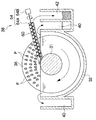
図3は、本発明の磁気分離装置20の一部を断面で示した斜視図であり、図4は側面断面図、図5は正面断面図である。
[Magnetic separator]
3 is a perspective view showing a part of the
これらの図に示すように、本発明の磁気分離装置20は、主として、磁性フロックFを含有する原水が流入する分離槽32と、分離槽32内に水平方向に配設された回転軸34に所定間隔を有して並設され、磁性フロックFを磁性力により吸着する複数枚の磁気ディスク36と、磁気ディスク36に吸着された磁性フロックFを回収する回収手段38とで構成される。尚、本実施の形態では3枚又は4枚の磁気ディスク36の例で説明するが、枚数には限定されない。
As shown in these drawings, the
分離槽32は、上面が開放されると共に、両端面が側壁41(図5参照)で閉塞された半円筒形状に形成される。分離槽32の両側(図3の左右)には、回転軸34と平行に形成された断面凹状の一対のトラフ40が分離槽32と一体形成されると共に、トラフ40の外側には、トラフ40と平行な断面凹状のフロック回収槽42が設けられる。尚、フロック回収槽42は、図3に示すように、回転する磁気ディスク36が原水中に進入する右側(図3の右側)に設けられる。
The
また、図5のように、分離槽32の一対の側壁41の上部には、軸受35を介して回転軸34が回転自在に支持されると共に、回転軸34の一端がモータ39に連結される。そして、回転軸34には、中心部に嵌合穴を有する複数枚の磁気ディスク36が所定間隔を有して嵌合支持される。磁気ディスク36同士の間には、磁気ディスク36同士の間隔を調整すると共に、磁気ディスク36の内周部を固定するスリーブ31が設けられる。磁気ディスク36同士の間隔は、磁気ディスク36の厚みに対して1倍〜3倍の範囲に設定することが好ましい。間隔が1倍未満では原水が磁気ディスク36同士の間に流れ込みにくくなると共に、3倍を超えて広過ぎると磁気ディスク36同士の間に強い磁性力を発生しにくくなる。
Further, as shown in FIG. 5, the rotating
また、回転軸34に支持された複数枚の磁気ディスク36は、分離槽32内の原水中に1/2〜2/3の割合で水没させることが好ましい。このように磁気ディスク36を部分的に水没させた構成の場合には、原水中で磁気ディスク36に吸着させた磁性フロックFを、磁気ディスク36が回転して磁性フロックFが大気中に搬送されたときに回収手段38で回収することになる。従って、磁性フロックFの吸着と回収との効率が最も良くなるように、磁気ディスク36の水没率を設定することが重要である。このためには例えば、回転軸34を回転自在に支持する一対の軸受35を、図示しない一対の昇降装置に支持させて、磁気ディスク36を油圧機構等により昇降させることにより水没率を可変できるように構成することも良い方法である。
The plurality of
また、分離槽32の下端には、回転軸34の軸線方向に長い四角筒形状の給水口44が形成され、この給水口44と凝集装置14の出口とが四角筒状の配管43(図4参照)で接続される。給水口44には、複数の分流部材46(図5参照)が配設される。この分流部材46は、図5に示すように、それぞれの磁気ディスク36の真下に配置され、上端面の厚みW1が磁気ディスク36の厚みW2と同等に形成されると共に、下端にいくに従って厚みが薄くなる断面楔形状に形成される。また、図4から分かるように、分流部材46の幅寸法D1は、給水口44の幅D2よりも小さく、給水口44に給水された原水が給水口44と分流部材46との間に形成された左右の隙間44A、44Bに分流されるように構成される。
Further, at the lower end of the
この分流部材46により、給水口44から給水された原水は、分流部材46に衝突して図4に示すように磁気ディスク36の径方向左右に分流される。このように、給水口44から給水された原水が分流部材46に衝突して左右方向へ2つの流れとして分流されることにより、磁気ディスク36同士の間を流れる原水の流速が減速され、磁気ディスク36同士の間をゆっくりとした上向流となって上昇する。これにより、原水中の磁性フロックFを磁気ディスク36に効率的に吸着することができる。また、上向流の流速を減速することで、磁気ディスク36に一旦吸着した磁性フロックFが剥離しにくくなる。
The
また、分流部材46により、給水口44から分離槽32内に流入した原水は、図5に示すように、磁気ディスク36の厚み方向にも分流される。これにより、磁気ディスク36に吸着した磁性フロックFが、給水口44から給水された原水の水流で剥離することを防止できる。即ち、図5から分かるように、楔形状の分流部材46を設けないと、磁気ディスク36の外周面36aが給水口44から給水された原水の上向流に直接曝されることになる。
Further, the raw water that has flowed into the
即ち、図6に示すように、分流部材46がない状態における原水の流れは、点線で示すように流速の速い上向流となって磁気ディスク36の面近傍を流れるので、磁性フロックF面に吸着した磁性フロックFのうち、特に外周面36a部分に近い磁性フロックFが原水の流れで掻き取られて原水中に脱落してしまう。これに対して、分流部材46により磁気ディスク36の外周面36aを原水の流れに直接曝さないようにすることで、給水口44から流入した原水は、図5の実線で示すように、分流部材46に当たって流速が遅くなり、更に磁気ディスク36の厚み方向に分流される。これにより、磁気ディスク面に一旦吸着された磁性フロックFが原水の流れで掻き取られることがない。
That is, as shown in FIG. 6, the flow of the raw water in the state without the
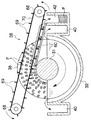
また、図4に示すように、分離槽32には、磁気ディスク36の外周面36aと分離槽32内面との隙間をシールして、給水口44から給水された原水が磁気ディスク36の外周面36aをショートパスしてトラフ40に流出しないためのシール板48が設けられる。
As shown in FIG. 4, in the
シール板48は、図7に示すように、基端部が分離槽32に回動自在に支持された回動軸50に固定されると共に、先端部が自由端として磁気ディスク36の外周面36aに接触している。そして、回動軸50は図示しないスプリング等により矢印方向に回転付勢されている。これにより、シール板48は、磁気ディスク36の外周面36aに対して所定の接触力で当接するので、磁気ディスクの回転を阻害することなく、原水が磁気ディスク36の外周面36aをショートパスすることを防止できる。シール板48の材質としては、磁気ディスク36よりも柔らかい弾性体が好ましく、例えばゴム板を好適に使用できる。
As shown in FIG. 7, the
次に、磁気ディスク36について説明する。
Next, the
磁気ディスク36は、内部にドーナッ状の空洞が形成された非磁性体のケース45内部に、永久磁石片37に挟まれた強磁性体のディスク基板33が配置されて構成される。尚、ディスク基板33の中心部には、回転軸34に挿通するための孔が形成されている。そして、回転軸34には通常3枚以上の磁気ディスク36が配設される。
The
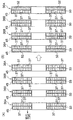
かかる複数枚の磁気ディスク36について、従来は図8(A)に示すように、回転軸34の両端部に配置される最外側磁気ディスク36Aも、回転軸34の両端より内側中央寄りに配置される内側磁気ディスク36Bも、強磁性体のディスク基板33の両面に永久磁石片37を配設していた。この為、最外側磁気ディスク36Aから分離槽32外への磁気漏れの問題や、最外側磁気ディスク36Aの変形の問題が生じていた。
Conventionally, as shown in FIG. 8A, the outermost
内側磁気ディスク36Bの場合には、両側に対向する磁気ディスクが存在するので、磁気ディスク36が等間隔で配置される限り、内側磁気ディスク36Bの磁性力が平衡状態を保つので、磁気漏れや変形の心配はない。
In the case of the inner
この対策として、図8(B)に示すように、内側磁気ディスク36Bについては従来通りディスク基板33の両面に永久磁石片37を配置し、強磁性体のディスク基板33を永久磁石片37同士で挟むようにする。一方、最外側磁気ディスク36Aについては、ディスク基板33両面の内側面(内側磁気ディスク36Bの側の面)のみに磁性力を発揮するための永久磁石片37を配置し、ディスク基板33の外側面には一枚の鉄板52を配置して、ディスク基板33を磁石と鉄板52で挟むようにした。この場合、ディスク基板33は、本質的に強磁性体であるが、鉄板52は強磁性体でも非磁性体でもよい。また、ディスク基板33と鉄板52とは、一枚の厚い強磁性体で一体物として構成してもよい。これにより、最外側磁気ディスク36Aの剛性を内側磁気ディスク36Bの剛性よりも大きくなるようにした。最外側磁気ディスク36Aのディスク基板33の剛性をどの程度大きくするかは、内側磁気ディスク36Bの磁性力に抗して最外側磁気ディスク36Aが変形しないことが必要である。従って、最外側磁気ディスク36Aと内側磁気ディスク36Bとの距離、永久磁石片37の磁性力、ディスク基板33の材質等により、鉄板52の厚みを適宜設定するとよい。
As a countermeasure against this, as shown in FIG. 8B, for the inner
最外側磁気ディスク36Aの場合も内側磁気ディスク36Bの場合も、強磁性体でディスク基板33を製作する場合には、永久磁石片37を磁気力によりディスク基板33に直接貼り付けることも可能であるが、接着剤で貼り付ける方法がより好ましい。この際に、ケース45内部に形成される空間に樹脂をモールドする構造形態も可能である。
In the case of the outermost
また、磁気ディスク36の剛性を高めるためには強磁性体のディスク基板33の面に永久磁石片37を嵌め込むポケット部(図示せず)を取り付けて、このポケット部に永久磁石片37を嵌め込むようにしてもよい。
In order to increase the rigidity of the
ディスク基板33の面に多数の永久磁石片37が固定された磁気ディスク36の製作方法としては、ディスク基板33を、基板33両面のうちの少なくとも一方面に多数の穴である上記のポケット部を有するハニカム構造に形成するディスク基板形成工程と、形成されたディスク基板33のポケット部に永久磁石片37を嵌め込む磁石嵌め込み工程と、永久磁石片37が嵌め込まれたディスク基板33を、内部にドーナッ状の空洞が形成されたケース45内部に収納する収納工程と、で構成される。
As a manufacturing method of the
これにより、ポケット部の側壁がリブ(補強材)の役目をするので、剛性を高めることができる。この場合、ポケット部は、非磁性体の材料で形成することが必要であり、ポケット部を強磁性体のディスク基板33に接着剤で貼り付ける。これは、ポケット部を磁性体(特に強磁性体)で形成すると、ポケット部の側壁に磁束が吸収され、結果として磁石表面近傍の磁場だけが強くなり、磁化方向に関し永久磁石片37から離れた一に高い磁場が作りにくくなるためである。
Thereby, since the side wall of a pocket part plays the role of a rib (reinforcement material), rigidity can be improved. In this case, the pocket portion needs to be formed of a non-magnetic material, and the pocket portion is attached to the
このように最外側磁気ディスク36Aを構成することにより、簡単な対策で磁気シールドや磁気コイルを設けなくても磁気漏れを解消でき、しかも最外側磁気ディスク36Aが変形することもない。尚、ポケット部を備えた内側磁気ディスク36Bを製作するには、ディスク基板33の両面にポケット部を形成すればよい。
By configuring the outermost
しかし、最外側磁気ディスク36Aのディスク基板33の外側面に永久磁石片37を配設しないことにより、最外側磁気ディスク36Aの外側面と分離槽32内面との間を通過した原水は、磁性フロックFが吸着分離されないままトラフに流出する危険がある。この対策として、図5に示すように、最外側磁気ディスク36Aの外側面と分離槽32内面との間隙が、最外側磁気ディスク36Aの回転を阻害しない遮蔽部材54で埋設されるようにした。遮蔽部材54としては、最外側磁気ディスク36Aの回転を阻害しないことが必要であり、樹脂やスポンジ等の摩擦が小さく柔らかい素材のものを好適に使用することができる。これにより、最外側磁気ディスク36Aの外側面に永久磁石片37を配設しなくても、磁性フロックFがそのままトラフ40に流出してしまうことはない。図5から分かるように、遮蔽部材54でシールしても、最外側磁気ディスク36Aの外側面と分離槽32内面との間に凹状の隙間が形成されるが、最外側磁気ディスク36Aが回転することで遠心力が作用するので、凹状の隙間に原水が滞留することはない。
However, since the
また、最外側磁気ディスク36Aの剛性を高めるためには、磁気ディスク36のケース45自体をハニカム構造にする方法があり、この方法を採用することで、磁気ディスク36の軽量化を図ることもできる。このハニカム構造の方法は、最外側磁気ディスク36Aに限らず、内側磁気ディスク36Bについても適用できる。
Further, in order to increase the rigidity of the outermost
次に、磁気ディスク36に吸着された磁性フロックFを回収するフロック回収手段38について説明する。
Next, the flock collecting means 38 for collecting the magnetic flock F attracted to the
フロック回収手段38は、主として、樋状スクレーパ60と、搬送手段62とで構成される。
The flock collecting means 38 is mainly composed of a bowl-shaped
樋状スクレーパ60は、回転する磁気ディスク36が大気中から原水中に進入する直前の磁気ディスク36同士の間に(図5参照)、回転軸34近傍からフロック回収槽42の上方まで樋状に配設される。そして、樋状スクレーパ60の両側面上端のエッジ部分60Aが磁気ディスク36の面に所定の付勢力を有して当接することにより、磁気ディスク36の面に吸着された磁性フロックFを掻き取るように構成される。
The hook-shaped
また、搬送手段62は、樋状スクレーパ60内に配設され、掻き取られて樋状スクレーパ60内に落下堆積した磁性フロックFをフロック回収槽42の上方に搬送してフロック回収槽42に落下させる。搬送手段62としては、スクリューコンベア64やヒレ付きベルトコンベア66を好ましく使用することができ、図9〜図11はスクリューコンベア64の場合であり、図12、図13はヒレ付きベルトコンベア66の場合である。尚、図9、図10、図12では、磁気ディスク36の大気中部分のみに磁性フロックFを図示した。
Further, the conveying means 62 is disposed in the bowl-shaped
図9に示すように、樋状スクレーパ60は、側面の上端エッジ部分60Aが磁気ディスク36の面に所定の押圧力を有して当接していると共に、上端エッジ部分60Aはシャープな薄肉形状に形成される。これにより、時計周り方向に回転する磁気ディスク36の面に吸着された磁性フロックFは、樋状スクレーパ60の上端エッジ部分60Aで掻き取られ、樋状スクレーパ60内に落下する。
As shown in FIG. 9, the bowl-shaped
図9〜図11に示すように、樋状スクレーパ60内には、スクリューコンベア64のスクリュー部64Aが収納され、スクリュー部64Aの一端がモータ64Bに連結される。この場合、図11に示すように、樋状スクレーパ60の側面から底面に至る内面形状は、搬送のデッドスペースが形成されないように半円状にすることが好ましい。これにより、樋状スクレーパ60内に落下堆積された磁性フロックFは、スクリューコンベア64によりフロック回収槽42の上方まで搬送され、フロック回収槽42に落下する。
As shown in FIGS. 9 to 11, a
また、搬送手段62として、ヒレ付きベルトコンベア66を採用する場合には、図12、図13に示すように構成される。即ち、ヒレ付きベルトコンベア66は、磁気ディスク36の径方向両側に一対のプーリ68が配置され、この一対のプーリ同士の間に、ヒレ69を有する無端状ベルト70が巻き懸けられる。また、一対のプーリ68のうちの一方が図示しないモータ等の駆動手段に連結される。この無端状ベルト70は、磁気ディスク36の面には接触しない。ヒレ69は無端状ベルト70の外側面に所定間隔を置いて多数配置され、無端状ベルト70に対して垂直に形成される。この場合、図13に示すように、樋状スクレーパ60の側面から底面に至る内面形状は、搬送のデッドスペースが形成されないようにヒレ69の形状に合わせることが好ましい。例えば、ヒレ69の形状を逆台形にした場合には、樋状スクレーパ60の内面形状も逆台形にする。
Further, when a finned belt conveyor 66 is employed as the conveying means 62, it is configured as shown in FIGS. That is, in the belt conveyor 66 with fins, a pair of
尚、図9〜図13では、樋状スクレーパ60の支持構造やヒレ付きベルトコンベア66のプーリ68の支持構造については特に示していないが、例えば磁気分離装置20の装置本体に支持することができる。また、樋状スクレーパ60の傾きについては、図10(スクリューコンベア)では右上がりで示し、図12(ヒレ付きベルトコンベア)では右下がりで示したが、右上がりに形成することがより好ましい。これは、樋状スクレーパ60内に落下体積した磁性フロックFが搬送手段62で搬送される間に、磁性フロック中の水分が樋状スクレーパ60を伝って流れるが、右上がりにすることで、水分がフロック回収槽42に流れ込むことを防止できる。フロック回収槽42に回収する磁性フロックFはできるだけ低水分にして減容化を図ることが重要である。この為、樋状スクレーパ60の右上がりの傾きを調整できるように、回収手段38全体の傾きを調整する調整手段(図示せず)を設けることが好ましい。例えば、スクリューコンベア方式の回収手段38の場合には、樋状スクレーパ60の長さ方向中心部を回動軸で支持するようにして、シリンダ装置等の伸縮装置により樋状スクレーパ60をシーソーのように揺動可能に構成することもできる。
9 to 13 do not particularly show the support structure of the bowl-shaped
次に、上記の如く構成された磁気分離装置20の作用について説明する。
Next, the operation of the
磁性フロックFを含有した原水は、分離槽32の下端に形成された給水口44から流入し、分流部材46によって分流される。この分流部材46によって、原水は連続回転する磁気ディスク36の面に対して左右両側に分流されると共に、磁気ディスク36同士の間の強磁性空間に流れ込むように分流される。分流された原水が分離槽32内を上昇する途中で、原水中の磁性フロックFが磁気ディスク36の面に吸着される。磁性フロックFが吸着されて浄化された処理水は、磁性フロックFの左右両側に設けられた一対のトラフ40に越流する。
The raw water containing the magnetic floc F flows from the
一方、磁気ディスク36に吸着された磁性フロックFは、磁気ディスク36の連続回転により水面上の大気中に搬送され、大気中に露出する。磁性フロックFが大気中に露出することにより、磁性フロックFの水分が重力により磁気ディスク36の面を伝って分離槽32内に流れ落ちる。更に、磁気ディスク36に吸着された磁性フロックFは、磁気ディスク36の磁性力により圧密化される。これにより、磁性フロックFの脱水が促進され、含水率が約90%のスラッジ状になる。
On the other hand, the magnetic floc F attracted to the
脱水が促進された磁性フロックFは、磁気ディスク36の連続回転により樋状スクレーパ60の位置まで搬送され、樋状スクレーパ60の側面エッジ部分60Aで掻き取られ、樋状スクレーパ60内に落下する。樋状スクレーパ60内に落下した磁性フロックFは、スクリューコンベア64又はヒレ付きベルトコンベア66の搬送手段62により搬送されて、フロック回収槽42の上方まで搬送されてフロック回収槽42に落下する。
The magnetic floc F whose dehydration has been promoted is transported to the position of the bowl-shaped
かかる磁気分離装置20による磁性フロックFの磁気分離において、複数枚の磁気ディスク36の真下に分流部材46を設けたので、原水中の磁性フロックFを磁気ディスク36に効率的に吸着することができる。
In the magnetic separation of the magnetic floc F by the
また、磁気ディスクと分離槽との間にシール板48を設けたことにより、磁性力が発揮されない磁気ディスク36の外周面を原水がショ―トパスしてトラフ40に越流しないようにできる。これにより、トラフ40に越流する処理水の水質が悪化することがない。
Further, by providing the
また、回転軸34に配設された複数枚の磁気ディスク36のうち、内側磁気ディスク36Bについては従来通りディスク基板33の両面に永久磁石片37を配置する一方、最外側磁気ディスク36Aについては、ディスク基板33の内側面(内側磁気ディスクの側の面)のみに磁性力を発揮するための永久磁石片37を配設した。そして、最外側磁気ディスク36Aの永久磁石片を配設するディスク基板33の剛性が内側磁気ディスクのディスク基板の剛性よりも大きくなるようにした。この場合、ハニカム構造の磁気ディスク36を採用すれば、必要な剛性を確保した上で、軽量化を図ることができる。
In addition, among the plurality of
更には、最外側磁気ディスク36Aの外側面と分離槽32内面との間に遮蔽部材54を埋め込むようにした。これにより、最外側磁気ディスク36Aからの磁性漏れや変形を防止できると共に、最外側磁気ディスク36Aの外側面を原水が通過してトラフ40に越流しないので、処理水の水質が悪くなることもない。
Further, the shielding
また、回収手段38として、樋状スクレーパ60を設けたことで、磁気ディスク36に吸着した磁性フロックFを確実に回収することができる。
Further, since the bowl-shaped
10…汚濁水浄化システム、12…原水ポンプ、14…凝集装置、14A…急速攪拌槽、14B…緩速攪拌槽、16…磁性粉添加装置、18…凝集剤添加装置、19…攪拌羽根、20…磁気分離装置、24…フィルター分離装置、25…脱水装置、26…回転ドラムフィルタ、28…シャワーリング装置、29…循環ポンプ、30…ポンプ、31…スリーブ、32…分離槽、33…ディスク基板、34…回転軸、35…軸受、36…磁気ディスク、37…永久磁石片、38…回収手段、39…モータ、40…トラフ、41…側壁、42…フロック回収槽、43…四角筒状の配管、44…給水口、45…ケース、46…分流部材、48…シール板、50…回動軸、52…補強部材、55…蓋部材、60…樋状スクレーパ、62…搬送手段、64…スクリューコンベア、66…ヒレ付きベルトコンベア、68…プーリ、69…ヒレ、70…無端状ベルト、F…磁性フロック
DESCRIPTION OF
Claims (5)
前記複数枚の磁気ディスクが前記分離槽の原水中に略半水没されるように配置され、前記分離槽の下端に形成された給水口から前記原水を分離槽内に上向流として給水すると共に、
前記複数枚のそれぞれの磁気ディスクの真下には、前記給水口から給水された原水を前記磁気ディスク面の左右方向及び前記磁気ディスクの厚み方向に分流する分流部材が配設され、
前記分離槽の前記回転軸と平行な両側には、前記磁気ディスクにより原水中の磁性フロックが除去された処理水が越流する一対のトラフが設けられ、
前記分流部材は前記原水を分流し、各分流された原水を隣接する磁気ディスク間の間隙に流れ込むように案内することを特徴とする磁気分離装置。 A separation tank into which raw water containing magnetic floc flows, and a plurality of magnetic disks arranged in parallel with a predetermined interval on a rotating shaft disposed in the separation tank and adsorbing the magnetic floc by magnetic force; In a magnetic separation device comprising a collecting means for collecting the adsorbed magnetic floc,
The plurality of magnetic disks are arranged so as to be submerged in the raw water of the separation tank, and the raw water is supplied into the separation tank as an upward flow from a water supply port formed at the lower end of the separation tank. ,
Directly below each of the plurality of magnetic disks, a diversion member is arranged to divert raw water supplied from the water supply port in the left-right direction of the magnetic disk surface and the thickness direction of the magnetic disk,
On both sides of the separation tank parallel to the rotation axis, a pair of troughs where the treated water from which the magnetic flocs in the raw water have been removed by the magnetic disk overflow are provided ,
The magnetic separation device is characterized in that the diversion member diverts the raw water and guides the diverted raw water so as to flow into a gap between adjacent magnetic disks .
回転する磁気ディスクが大気中から原水中に進入する直前の磁気ディスク同士の間に、前記回転軸の近傍から前記分離槽の外部まで樋状に配設され、両側面上端のエッジ部分が磁気ディスク面に所定の付勢力を有して当接することにより、磁気ディスク面に吸着された磁性フロックを掻き取る樋状スクレーパと、
樋状スクレーパ内に配設され、掻き取られて樋状スクレーパ内に落下堆積した磁性フロックを前記分離槽の外部まで搬送する搬送手段と、を備えたことを特徴とする請求項1〜4の何れか1の磁気分離装置。 The recovery means includes
Between the magnetic disks just before the rotating magnetic disk enters the raw water from the atmosphere, it is arranged in a bowl shape from the vicinity of the rotating shaft to the outside of the separation tank, and the edge portions at the upper ends of both side surfaces are magnetic disks. A bowl-shaped scraper that scrapes the magnetic floc adsorbed on the magnetic disk surface by contacting the surface with a predetermined urging force;
5. A conveying means disposed in the bowl-shaped scraper, for conveying the magnetic floc scraped off and deposited in the bowl-shaped scraper to the outside of the separation tank. Any one of the magnetic separation devices.
Priority Applications (6)
| Application Number | Priority Date | Filing Date | Title |
|---|---|---|---|
| JP2008019094A JP5115219B2 (en) | 2007-10-01 | 2008-01-30 | Magnetic separation device |
| CN2008101689054A CN101402065B (en) | 2007-10-01 | 2008-09-27 | Magnetic separation device |
| KR1020080095411A KR101544614B1 (en) | 2007-10-01 | 2008-09-29 | Magnetic separation device |
| CA2640019A CA2640019C (en) | 2007-10-01 | 2008-09-29 | Magnetic separation apparatus |
| PCT/JP2008/067715 WO2009044719A1 (en) | 2007-10-01 | 2008-09-30 | Magnetic separation device |
| MX2010003429A MX2010003429A (en) | 2007-10-01 | 2008-09-30 | Magnetic separation device. |
Applications Claiming Priority (3)
| Application Number | Priority Date | Filing Date | Title |
|---|---|---|---|
| JP2007257791 | 2007-10-01 | ||
| JP2007257791 | 2007-10-01 | ||
| JP2008019094A JP5115219B2 (en) | 2007-10-01 | 2008-01-30 | Magnetic separation device |
Publications (2)
| Publication Number | Publication Date |
|---|---|
| JP2009101339A JP2009101339A (en) | 2009-05-14 |
| JP5115219B2 true JP5115219B2 (en) | 2013-01-09 |
Family
ID=40536309
Family Applications (1)
| Application Number | Title | Priority Date | Filing Date |
|---|---|---|---|
| JP2008019094A Expired - Fee Related JP5115219B2 (en) | 2007-10-01 | 2008-01-30 | Magnetic separation device |
Country Status (4)
| Country | Link |
|---|---|
| JP (1) | JP5115219B2 (en) |
| KR (1) | KR101544614B1 (en) |
| CN (1) | CN101402065B (en) |
| MX (1) | MX2010003429A (en) |
Cited By (1)
| Publication number | Priority date | Publication date | Assignee | Title |
|---|---|---|---|---|
| US10225899B2 (en) | 2015-04-14 | 2019-03-05 | Kowa Company, Ltd. | Light system for plant cultivation |
Families Citing this family (17)
| Publication number | Priority date | Publication date | Assignee | Title |
|---|---|---|---|---|
| JP5208835B2 (en) * | 2009-03-31 | 2013-06-12 | 株式会社日立プラントテクノロジー | Coagulation / separation device for treated water |
| JP2011121033A (en) | 2009-12-14 | 2011-06-23 | Hitachi Plant Technologies Ltd | Magnetic separation apparatus and magnetic separation method, wastewater treatment apparatus, and wastewater treatment method |
| JP5485750B2 (en) * | 2010-03-05 | 2014-05-07 | 株式会社日立製作所 | Magnetic separation device and wastewater treatment device |
| CN102603042A (en) * | 2012-03-28 | 2012-07-25 | 四川环能德美科技股份有限公司 | Magnetic separating magnetic drum |
| JP5730421B2 (en) * | 2014-02-18 | 2015-06-10 | 株式会社日立製作所 | Magnetic separation device and wastewater treatment device |
| CN106241973A (en) * | 2015-09-09 | 2016-12-21 | 无锡亮慧环保机械有限公司 | The Magnetic Isolation processing means of sludge water |
| CN106241927A (en) * | 2015-09-09 | 2016-12-21 | 无锡亮慧环保机械有限公司 | The sewage treating apparatus separated with bubble auxiliary |
| CN105565446B (en) * | 2016-02-04 | 2018-04-13 | 青岛太平洋化工装备有限公司 | Add magnetic flocculation advanced water purifying system |
| CN106186218A (en) * | 2016-08-24 | 2016-12-07 | 安徽清普环保装备有限公司 | A kind of board-like magnetic separating device |
| CN106746148B (en) * | 2017-03-17 | 2023-08-01 | 成都源蓉科技有限公司 | Magnetic loading sedimentation filtration purification system |
| CN110342646B (en) * | 2019-07-03 | 2024-06-11 | 王超 | Microorganism sewage treatment system and sewage treatment method |
| CN114100851B (en) * | 2020-08-27 | 2023-11-14 | 宝山钢铁股份有限公司 | Magnetic impurity treatment system |
| CN114162580A (en) * | 2022-01-08 | 2022-03-11 | 安徽普氏生态环境工程有限公司 | Magnetic separator applying composite scraper |
| CN115259534B (en) * | 2022-08-10 | 2024-02-06 | 鞍山市松楠矿用机械制造有限公司 | Water treatment method and equipment for sand aggregate production |
| CN115557622B (en) * | 2022-08-22 | 2024-07-26 | 广东常绿环保科技有限公司 | Intelligent adjustable sewage treatment equipment for reworking enterprises |
| CN118384587A (en) * | 2023-03-28 | 2024-07-26 | 李菊香 | Pharmaceutical wastewater floccule filtering equipment |
| CN118681689A (en) * | 2024-07-02 | 2024-09-24 | 云浮市云安区颂鑫建筑陶瓷原料有限公司 | An intelligent processing device for quartz sand |
Family Cites Families (8)
| Publication number | Priority date | Publication date | Assignee | Title |
|---|---|---|---|---|
| JP2930107B2 (en) * | 1992-03-02 | 1999-08-03 | 日立プラント建設株式会社 | Sewage treatment equipment |
| JP3241462B2 (en) * | 1992-07-10 | 2001-12-25 | 稲葉 栄子 | Method and apparatus for magnetically coagulating impurities in liquid |
| JPH10244424A (en) * | 1997-02-28 | 1998-09-14 | Makino Milling Mach Co Ltd | Processing waste separation equipment for electric discharge machines |
| JP4139547B2 (en) * | 1999-11-02 | 2008-08-27 | 株式会社日立製作所 | Membrane magnetic separator |
| CN2412658Y (en) * | 2000-03-20 | 2001-01-03 | 四川冶金环能工程有限责任公司 | Rare-earth magnetic dick separation purifying apparatus |
| JP3325010B2 (en) * | 2000-05-09 | 2002-09-17 | 株式会社プロジェクト・オーガン | Magnetic solid-liquid separator |
| JP2002066375A (en) * | 2000-08-31 | 2002-03-05 | Hitachi Ltd | Magnetic separation device for removal |
| JP2002102745A (en) * | 2000-09-29 | 2002-04-09 | Japan Science & Technology Corp | Magnetic separation device |
-
2008
- 2008-01-30 JP JP2008019094A patent/JP5115219B2/en not_active Expired - Fee Related
- 2008-09-27 CN CN2008101689054A patent/CN101402065B/en not_active Expired - Fee Related
- 2008-09-29 KR KR1020080095411A patent/KR101544614B1/en not_active Expired - Fee Related
- 2008-09-30 MX MX2010003429A patent/MX2010003429A/en active IP Right Grant
Cited By (1)
| Publication number | Priority date | Publication date | Assignee | Title |
|---|---|---|---|---|
| US10225899B2 (en) | 2015-04-14 | 2019-03-05 | Kowa Company, Ltd. | Light system for plant cultivation |
Also Published As
| Publication number | Publication date |
|---|---|
| CN101402065A (en) | 2009-04-08 |
| KR20090033801A (en) | 2009-04-06 |
| CN101402065B (en) | 2013-06-05 |
| KR101544614B1 (en) | 2015-08-17 |
| JP2009101339A (en) | 2009-05-14 |
| MX2010003429A (en) | 2010-06-09 |
Similar Documents
| Publication | Publication Date | Title |
|---|---|---|
| JP5115219B2 (en) | Magnetic separation device | |
| JP5115220B2 (en) | Magnetic separation device | |
| JP4648917B2 (en) | Magnetic separation filtration purification device | |
| CA2640019C (en) | Magnetic separation apparatus | |
| JP5019074B2 (en) | Magnetic separation device | |
| CA2567693C (en) | Magnetic separation purifying apparatus and magnetic separation purifying method | |
| US20080073284A1 (en) | Device and method for utilizing magnetic seeding and separation in a water treatment system | |
| US20070039894A1 (en) | Water treatment using magnetic and other field separation technologies | |
| KR101728529B1 (en) | Treatment apparatus for sewage | |
| US20080073280A1 (en) | Device for Removing Magnetic Floc from a Magnetic Collector in a Water Treatment System | |
| US20080073283A1 (en) | Magnetic Separator for Water Treatment System | |
| US20160221845A1 (en) | Magnetic ballast clarification designs and applications | |
| JP4317668B2 (en) | Membrane magnetic separator | |
| JP5115221B2 (en) | Magnetic disk, manufacturing method thereof, and magnetic separation device | |
| JP6282455B2 (en) | Filtration device | |
| CA2639885C (en) | Magnetic separation apparatus, magnetic disk and method of forming magnetic disk | |
| KR101544613B1 (en) | Magnetic separation apparatus magnetic disk and method of forming magnetic disk | |
| JP4821085B2 (en) | Magnetic separation and purification apparatus and magnetic separation and purification method | |
| KR100852312B1 (en) | Magnetic Separation Purification Device and Magnetic Separation Purification Method | |
| WO2006112007A1 (en) | Apparatus for water filtration/purification and method thereof | |
| KR20040033932A (en) | sewage disposal system | |
| KR200201954Y1 (en) | Assistant apparatus of sludge removal apparatus | |
| CN224062523U (en) | Full-automatic dirt-cleaning and scale-removing instrument | |
| JP2012148226A (en) | Magnetic separator | |
| AU2005331412B2 (en) | Magnetic separation cleaning apparatus and magnetic separation cleaning method |
Legal Events
| Date | Code | Title | Description |
|---|---|---|---|
| A621 | Written request for application examination |
Free format text: JAPANESE INTERMEDIATE CODE: A621 Effective date: 20100302 |
|
| A131 | Notification of reasons for refusal |
Free format text: JAPANESE INTERMEDIATE CODE: A131 Effective date: 20120531 |
|
| A521 | Written amendment |
Free format text: JAPANESE INTERMEDIATE CODE: A523 Effective date: 20120723 |
|
| TRDD | Decision of grant or rejection written | ||
| A01 | Written decision to grant a patent or to grant a registration (utility model) |
Free format text: JAPANESE INTERMEDIATE CODE: A01 Effective date: 20120918 |
|
| A01 | Written decision to grant a patent or to grant a registration (utility model) |
Free format text: JAPANESE INTERMEDIATE CODE: A01 |
|
| A61 | First payment of annual fees (during grant procedure) |
Free format text: JAPANESE INTERMEDIATE CODE: A61 Effective date: 20121001 |
|
| R150 | Certificate of patent or registration of utility model |
Free format text: JAPANESE INTERMEDIATE CODE: R150 |
|
| FPAY | Renewal fee payment (event date is renewal date of database) |
Free format text: PAYMENT UNTIL: 20151026 Year of fee payment: 3 |
|
| S111 | Request for change of ownership or part of ownership |
Free format text: JAPANESE INTERMEDIATE CODE: R313111 |
|
| R350 | Written notification of registration of transfer |
Free format text: JAPANESE INTERMEDIATE CODE: R350 |
|
| LAPS | Cancellation because of no payment of annual fees |