JP5115324B2 - Focus detection apparatus and imaging apparatus - Google Patents
Focus detection apparatus and imaging apparatus Download PDFInfo
- Publication number
- JP5115324B2 JP5115324B2 JP2008128348A JP2008128348A JP5115324B2 JP 5115324 B2 JP5115324 B2 JP 5115324B2 JP 2008128348 A JP2008128348 A JP 2008128348A JP 2008128348 A JP2008128348 A JP 2008128348A JP 5115324 B2 JP5115324 B2 JP 5115324B2
- Authority
- JP
- Japan
- Prior art keywords
- light
- color
- focus detection
- light receiving
- correction value
- Prior art date
- Legal status (The legal status is an assumption and is not a legal conclusion. Google has not performed a legal analysis and makes no representation as to the accuracy of the status listed.)
- Expired - Fee Related
Links
Images






Landscapes
- Focusing (AREA)
- Automatic Focus Adjustment (AREA)
- Studio Devices (AREA)
Description
この発明は、焦点検出装置および撮像装置に関するものである。 The present invention relates to focal point detection apparatus and an imaging apparatus.
結像光学系の射出瞳の異なる領域を通過した一対の光束を一対の受光素子で受光し、それぞれの受光素子に形成される像ズレに基づいて焦点調節を行う焦点検出装置において、受光素子に入射する光量の、像高および受光素子の位置ずれに基づくアンバランスによる受光素子の出力変動を補正する焦点検出方法が知られている(特許文献1)。 In a focus detection apparatus that receives a pair of light beams that have passed through different regions of an exit pupil of an imaging optical system by a pair of light receiving elements and performs focus adjustment based on an image shift formed in each light receiving element, A focus detection method that corrects output fluctuation of a light receiving element due to imbalance based on an incident light quantity, an image height and a position shift of the light receiving element is known (Patent Document 1).
しかしながら、上記従来技術では、被写体によっては受光素子の出力むらは補正できないという問題があった。 However, the above conventional technique has a problem that output unevenness of the light receiving element cannot be corrected depending on the subject.
この発明が解決しようとする課題は、被写体によらず受光信号を補正することができる焦点検出装置および撮像装置を提供することである。 Problems which the present invention is to provide is to provide a focus that can be corrected point detection apparatus and an imaging apparatus a light reception signal regardless of the subject.
この発明は、以下の解決手段によって上記課題を解決する。なお、発明の実施形態を示す図面に対応する符号を付して説明するが、この符号は発明の理解を容易にするためだけのものであって発明を限定する趣旨ではない。 The present invention solves the above problems by the following means. In addition, although the code | symbol corresponding to drawing which shows embodiment of this invention is attached | subjected and demonstrated, this code | symbol is only for making an understanding of invention easy, and is not the meaning which limits invention.
[1]本発明の第1の観点に係る焦点検出装置は、複数の受光部(161dn)をそれぞれ有し、光束を受光して一対の受光信号を出力する一対の受光手段(161d)と、前記複数の受光部の位置に応じた第1補正値、及び、前記複数の受光部の位置に応じた、前記第1補正値とは異なる第2補正値を記憶する記憶手段(170)と、前記受光手段により受光される前記光束の色が第1色であるか、第2色であるかを判断する判断部(170)と、前記受光手段により受光される前記光束の色が前記第1色であると前記判断部により判断されたとき、前記第1補正値を用いて前記受光信号を補正し、前記受光手段により受光される前記光束の色が前記第2色であると前記判断部により判断されたとき、前記第1補正値及び前記第2補正値を用いて前記受光信号を補正する補正手段(170)と、前記補正手段により補正された前記一対の受光信号の相関を演算することで、前記光学系の焦点調節状態を検出する焦点検出手段(162,163)と、前記焦点検出手段による焦点検出結果に応じて、焦点調節光学系(211)の駆動を制御する制御手段(163,164)と、を備えることを特徴とする。 [1] A focus detection apparatus according to a first aspect of the present invention includes a pair of light receiving units (161d) each having a plurality of light receiving units (161dn) , receiving a light beam and outputting a pair of light receiving signals, Storage means (170) for storing a first correction value according to the positions of the plurality of light receiving units and a second correction value different from the first correction value according to the positions of the plurality of light receiving units ; A determination unit (170) for determining whether the color of the light beam received by the light receiving unit is the first color or the second color, and the color of the light beam received by the light receiving unit is the first color. When the determination unit determines that the color is a color, the determination unit corrects the light reception signal using the first correction value, and determines that the color of the light beam received by the light reception unit is the second color. When the first correction value and the second correction value are determined. And a correction means (170) for correcting the light reception signal and a focus detection means (162) for detecting the focus adjustment state of the optical system by calculating a correlation between the pair of light reception signals corrected by the correction means. 163) and control means (163, 164) for controlling the driving of the focus adjustment optical system (211) according to the focus detection result by the focus detection means .
上記発明において、前記第1補正値は、白色光源の光束に対する白色光源用補正値であり、前記第2補正値は、単色光源の光束の波長に起因して生じる前記一対の受光信号間の出力差に対応する傾き係数であるように構成することができる。また、上記発明において、前記補正手段(170)は、前記受光手段(161d)により受光される前記光束の色が前記第2色であると前記判断部(170)により判断されたとき、前記白色光源用補正値を用いて前記一対の受光信号を補正した後に、前記傾き係数を用いて補正した前記一対の受光信号のうちいずれか一方を補正するように構成することができる。 In the above invention, the first correction value is a white light source correction value for a light beam of a white light source, and the second correction value is an output between the pair of light reception signals generated due to the wavelength of the light beam of a monochromatic light source. It can be configured to have a slope coefficient corresponding to the difference . Further, in the above invention, the correction means (170) is configured such that when the determination unit (170) determines that the color of the light beam received by the light receiving means (161d) is the second color, After correcting the pair of light reception signals using the light source correction value, one of the pair of light reception signals corrected using the inclination coefficient can be corrected.
[2]本発明の第2の観点に係る焦点検出装置は、複数の受光部(161dn)をそれぞれ有し、光束を受光して一対の受光信号を出力する一対の受光手段(161d)と、前記複数の受光部の位置に応じた第1補正値、及び、前記複数の受光部の位置に応じた前記第1補正値とは異なる第2補正値を記憶する記憶手段(170)と、前記受光手段により受光される前記光束の色が第1色であるか、第2色であるかを判断する判断部(170)と、前記受光手段により受光される前記光束の色が前記第1色であると前記判断部により判断されたとき、前記第1補正値を用いて前記受光信号を補正し、前記受光手段により受光される前記光束の色が前記第2色であると前記判断部により判断されたとき、前記第2補正値を用いて前記受光信号を補正する補正手段(170)と、前記補正手段により補正された前記一対の受光信号の相関を演算することで、前記光学系の焦点調節状態を検出する焦点検出手段(162,163)と、前記焦点検出手段による焦点検出結果に応じて、焦点調節光学系の駆動を制御する制御手段(164,165)と、を備えることを特徴とする。[2] A focus detection apparatus according to a second aspect of the present invention includes a pair of light receiving units (161d) each having a plurality of light receiving portions (161dn), receiving a light beam and outputting a pair of light receiving signals, Storage means (170) for storing a first correction value according to the position of the plurality of light receiving parts and a second correction value different from the first correction value according to the positions of the plurality of light receiving parts; A determination unit (170) for determining whether the color of the light beam received by the light receiving unit is the first color or the second color, and the color of the light beam received by the light receiving unit is the first color When the determination unit determines that the received light signal is corrected by the first correction value, the determination unit determines that the color of the light beam received by the light receiving unit is the second color. When it is determined, the received light signal is converted using the second correction value. Correction means (170) for correcting, focus detection means (162, 163) for detecting a focus adjustment state of the optical system by calculating a correlation between the pair of light receiving signals corrected by the correction means, And control means (164, 165) for controlling the driving of the focus adjustment optical system according to the focus detection result by the focus detection means.
上記発明において、前記第1補正値は、白色光源による光束に対する白色光源用補正値であり、前記第2補正値は、単色光源による光束に対する単色光源用補正値であり、前記受光手段(161d)により受光される前記光束が白色であると前記判断部(170)により判断されたとき、前記第1補正値を用いて前記受光信号を補正し、前記受光手段により受光される前記光束が単色であると前記判断部により判断されたとき、前記第2補正値を用いて前記受光信号を補正するように構成することができる。また、上記発明において、被写体に対して単色光を照射する照射手段(303)を備え、前記判断部(170)は、前記照射手段による照射が行われていない場合には、前記受光手段により受光される前記光束が白色であると判断し、前記照射手段による照射が行われた場合には、前記受光手段により受光される前記光束が単色であると判断するように構成することができる。 In the above invention, the first correction value is a white light source correction value for a light beam by a white light source, and the second correction value is a single color light source correction value for a light beam by a monochromatic light source, and the light receiving means (161d) When the determination unit (170) determines that the light beam received by the light source is white, the light correction signal is corrected using the first correction value, and the light beam received by the light receiving unit is monochromatic. When it is determined by the determination unit that there is, the received light signal can be corrected using the second correction value . Further, in the above invention, an irradiating unit (303) for irradiating a subject with monochromatic light is provided, and the determination unit (170) receives light by the light receiving unit when irradiation by the irradiating unit is not performed. When the light beam is determined to be white and the irradiation unit performs irradiation, the light beam received by the light receiving unit may be determined to be monochromatic.
上記発明において、前記焦点検出手段(162,163)は、前記光学系による画面内に設定された焦点検出位置に対する前記焦点調節状態を検出し、前記光学系による像のうち、前記焦点検出位置に対応する像の色を検出する色検出手段(137)をさらに備え、前記補正手段(170)は、前記色検出手段により検出された色に応じた補正値により前記受光信号を補正するように構成することができる。 In the above invention, the focus detection means (162, 163) detects the focus adjustment state with respect to the focus detection position set in the screen by the optical system, and sets the focus detection position in the image by the optical system. It further comprises color detection means (137) for detecting the color of the corresponding image, and the correction means (170) is configured to correct the received light signal with a correction value corresponding to the color detected by the color detection means. can do.
上記発明において、前記受光手段(161d)は、前記光学系(210)を介した一対の光束(A,B)を受光するものであり、前記光学系と前記受光手段との間の前記光束の光路中に設けられた、前記一対の光束が入射する光学部品(121)を備え、前記補正手段(170)は、前記光学部品に対する前記一対の光束の入射角(α,β)が互いに異なる場合に、前記受光信号を補正するように構成することができる。 In the above invention, the light receiving means (161d) receives a pair of light beams (A, B) via the optical system (210), and the light beam between the optical system and the light receiving means. When provided with an optical component (121) that is provided in the optical path and on which the pair of light beams are incident, the correction means (170) has different incident angles (α, β) of the pair of light beams with respect to the optical components. In addition, the light receiving signal can be corrected.
[3]発明に係る撮像装置は、上記発明に係る焦点検出装置を備えたことを特徴とする。 [3] An image pickup apparatus according to the invention includes the focus detection device according to the invention.
上記発明において、被写体に対して光を照射する照射手段(303)を備え、前記補正手段(170)は、前記光の照射に応じて前記受光信号を補正するように構成することができる。 In the above invention, it is possible to provide an irradiating means (303) for irradiating the subject with light, and the correcting means (170) can be configured to correct the received light signal in accordance with the irradiation of the light.
また上記発明において、被写体の色を検出する色検出手段(137)を備え、前記補正手段(170)は、前記色検出手段により検出された色に応じて前記受光信号を補正するように構成することができる。 Further, in the above invention, color detection means (137) for detecting the color of the subject is provided, and the correction means (170) is configured to correct the light reception signal in accordance with the color detected by the color detection means. be able to.
上記発明によれば、被写体の色に応じて適切に受光信号のむらを補正することができる。 According to the above invention, it is possible to appropriately correct the unevenness of the received light signal according to the color of the subject.
以下においては、上記発明を一眼レフデジタルカメラに適用した実施形態を図面に基づいて説明する。ただし上記発明は、銀塩フィルムカメラやコンパクトカメラその他の撮像装置にも適用することができる。 In the following, an embodiment in which the above invention is applied to a single-lens reflex digital camera will be described with reference to the drawings. However, the above-described invention can also be applied to a silver salt film camera, a compact camera, and other imaging devices.
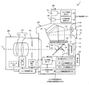
図1は、本実施形態に係る一眼レフデジタルカメラ1を示すブロック図であり、上記発明の受光装置、焦点検出装置および撮像装置に関する構成以外のカメラの一般的構成については、その図示と説明を一部省略する。 FIG. 1 is a block diagram illustrating a single-lens reflex digital camera 1 according to the present embodiment. The general configuration of the camera other than the configuration related to the light receiving device, the focus detection device, and the imaging device of the invention is illustrated and described. Some are omitted.
本実施形態の一眼レフデジタルカメラ1(以下、単にカメラ1という。)は、カメラボディ100とレンズ鏡筒200とストロボ装置300とを備え、カメラボディ100とレンズ鏡筒200は着脱可能に結合され、カメラボディ100とストロボ装置300も着脱可能に結合されている。
The single-lens reflex digital camera 1 (hereinafter simply referred to as camera 1) of the present embodiment includes a
レンズ鏡筒200には、フォーカスレンズ211やズームレンズ212を含むレンズ群210や絞り装置220などからなる撮影光学系が内蔵されている。
The
フォーカスレンズ211は、その光軸L1に沿って移動可能に設けられ、エンコーダ260によってその位置が検出されつつレンズ駆動モータ230によってその位置が調節される。そして、エンコーダ260で検出されたフォーカスレンズ211の位置情報は、レンズ制御部250を介して後述するレンズ駆動制御部165へ送信される。また、レンズ駆動モータ230は、後述する焦点検出結果に基づいて演算された駆動量や駆動速度に応じて、レンズ駆動制御部165からレンズ制御部250を介して受信される駆動信号により駆動する。
The
絞り装置220は、上記撮影光学系を通過して撮像素子110に至る光束の光量を制限するために、光軸L1を中心にした開口径が調節可能とされている。絞り装置220による開口径の調節は、たとえば自動露出モードにおいて演算された絞り値に応じた信号が、カメラ制御部170からレンズ制御部250を介して絞り駆動部240へ送信されることにより行われる。また、開口径の調節は、カメラボディ100に設けられた操作部150によるマニュアル操作により、設定された絞り値に応じた信号がカメラ制御部170からレンズ制御部250を介して絞り駆動部240へ送信されることによっても行われる。
The
一方、カメラボディ100は、被写体からの光束を撮像素子110、ファインダ135、測光センサ137及び焦点検出モジュール161へ導くためのミラー系120を備える。このミラー系120は、回転軸123を中心にして被写体の観察位置と撮影位置との間で所定角度だけ回転するクイックリターンミラー121と、このクイックリターンミラー121に軸支されてクイックリターンミラー121の回動に合わせて回転するサブミラー122とを備える。図1においては、ミラー系120が被写体の観察位置にある状態を実線で示し、被写体の撮影位置にある状態を二点鎖線で示す。
On the other hand, the
ミラー系120は、被写体の観察位置にある状態では光軸L1の光路上に挿入される一方で、被写体の撮影位置にある状態では光軸L1の光路から退避するように回転する。
The
クイックリターンミラー121はハーフミラーで構成され、被写体の観察位置にある状態では、被写体からの光束(光軸L1)の一部の光束(光軸L2,L3)を当該クイックリターンミラー121で反射してファインダ135および測光センサ137へ導き、一部の光束(光軸L4)を透過させてサブミラー122へ導く。これに対して、サブミラー122は全反射ミラーで構成され、クイックリターンミラー121を透過した光束(光軸L4)を焦点検出モジュール161へ導く。
The
したがって、ミラー系120が観察位置にある場合は、被写体からの光束(光軸L1)はファインダ135、測光センサ137および焦点検出モジュール161へ導かれ、撮影者により被写体が観察されるとともに、露出演算やフォーカスレンズ211の焦点調節状態の検出が実行される。そして、撮影者がレリーズボタンを全押しするとミラー系120が撮影位置に回動し、被写体からの光束(光軸L1)は全て撮像素子110へ導かれ、撮影した画像データを図示しないメモリに保存する。
Therefore, when the
焦点検出モジュール161は、被写体光を用いた位相差検出方式による自動合焦制御を実行するための焦点検出素子であり、サブミラー122で反射した光束(光軸L4)の、撮像素子110の撮像面と光学的に等価な位置に固定されている。
The
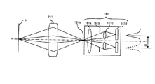
図2Aは、図1に示す焦点検出モジュール161の構成例を示す図、図2Bは図2Aに示すラインセンサ161dを拡大して示す正面図である。
2A is a diagram showing a configuration example of the
本例の焦点検出モジュール161は、コンデンサレンズ161a、一対の開口が形成された絞りマスク161b、一対の再結像レンズ161cおよび一対のラインセンサ161dを有し、フォーカスレンズ211の射出瞳の異なる一対の領域を通る一対の光束をラインセンサ161dで受光して得られる一対の像信号の位相ずれを周知の相関演算によって求めることにより焦点調節状態を検出する。ラインセンサ161dは、図2Bに示すように光軸L4に対して垂直方向に並ぶ複数の受光部161dnを有し、各受光部161dnから受光信号が出力される。
The
そして、図2Aに示すように被写体Pが撮像素子110の等価面(予定結像面)161eで結像すると合焦状態となるが、フォーカスレンズ211が光軸L1方向に移動することで、結像点が等価面161eより被写体側にずれたり(前ピンと称される)、カメラボディ100側にずれたりすると(後ピンと称される)、ピントずれの状態となる。
As shown in FIG. 2A, when the subject P forms an image on the equivalent surface (planned imaging surface) 161e of the
なお、被写体Pの結像点が等価面161eより被写体側にずれると、一対のラインセンサ161dで検出される一対の像信号の間隔Wが、合焦状態の間隔Wに比べて短くなり、逆に被写体像Pの結像点がカメラボディ100側にずれると、一対のラインセンサ161dで検出される一対の像信号の間隔Wが、合焦状態の間隔Wに比べて長くなる。
When the imaging point of the subject P is shifted from the equivalent surface 161e toward the subject, the interval W between the pair of image signals detected by the pair of
すなわち、合焦状態では一対のラインセンサ161dで検出される像信号がラインセンサの中心に対して重なるが、非合焦状態ではラインセンサの中心に対して各像信号がずれる、すなわち位相差が生じるので、この位相差(ずれ量)に応じた量だけフォーカスレンズ211を移動させることでピントを合わせる。
That is, in the in-focus state, the image signals detected by the pair of
図1に戻り、AF−CCD制御部162は、オートフォーカスモードにおいて、焦点検出モジュール161のラインセンサ161dのゲインや蓄積時間を制御するもので、焦点検出位置として選択された焦点検出エリア1352(図3B参照)に関する情報をカメラ制御部170から受け、この焦点検出エリア1352に相当する一対のラインセンサ161dにて検出された一対の像信号を読み出し、デフォーカス演算部163へ出力する。
Returning to FIG. 1, the AF-CCD control unit 162 controls the gain and accumulation time of the
デフォーカス演算部163は、AF−CCD制御部162から送られてきた一対の像信号のずれ量をデフォーカス量ΔWに変換し、これをレンズ駆動量演算部164へ出力する。 The defocus calculation unit 163 converts the shift amount of the pair of image signals sent from the AF-CCD control unit 162 into a defocus amount ΔW, and outputs this to the lens drive amount calculation unit 164.
レンズ駆動量演算部164は、デフォーカス演算部163から送られてきたデフォーカス量ΔWに基づいて、当該デフォーカス量ΔWに応じたレンズ駆動量Δdを演算し、これをレンズ駆動制御部165へ出力する。 The lens drive amount calculation unit 164 calculates a lens drive amount Δd corresponding to the defocus amount ΔW based on the defocus amount ΔW sent from the defocus calculation unit 163, and supplies this to the lens drive control unit 165. Output.
レンズ駆動制御部165は、レンズ駆動量演算部164から送られてきたレンズ駆動量Δdに基づいてレンズ駆動モータ230へ駆動指令を送出し、レンズ駆動量Δdだけフォーカスレンズ211を移動させる。
The lens drive control unit 165 sends a drive command to the lens drive motor 230 based on the lens drive amount Δd sent from the lens drive amount calculation unit 164, and moves the
撮像素子110は、カメラボディ100の、被写体からの光束の光軸L1上であって、レンズ群210を含む撮影光学系の予定焦点面となる位置に設けられ、その前面にシャッター111が設けられている。撮像素子110は、複数の光電変換素子が二次元に配列されたものであって、二次元CCDイメージセンサ、MOSセンサまたはCIDなどで構成することができる。この撮像素子110で光電変換された電気画像信号は、カメラ制御部170で画像処理されたのち図示しないメモリに保存される。なお、撮影画像を格納するメモリは内蔵型メモリやカード型メモリなどで構成することができる。
The
一方、クイックリターンミラー121で反射された被写体からの光束は、撮像素子110と光学的に等価な面に配置された焦点板131に結像し、ペンタプリズム133と接眼レンズ134とを介して撮影者の眼球に導かれる。このとき、透過型液晶表示器132は、焦点板131上の被写体像に焦点検出エリアマーク1352(図3B参照)などを重畳して表示するとともに、被写体像外のエリアにシャッター速度、絞り値、撮影枚数などの撮影に関する情報を表示する。これにより、撮影準備状態において、ファインダ134を通して被写体およびその背景ならびに撮影関連情報などを観察することができる。
On the other hand, the light beam from the subject reflected by the
操作部150は、シャッターレリーズボタンや撮影者がカメラ1の各種動作モードを設定するための入力スイッチであり、自動露出モード/マニュアル露出モード、オートフォーカスモード/マニュアルフォーカスモードの切換や、オートフォーカスモードの中でも、ワンショットモード/コンティニュアスモードの切換が行えるようになっている。また、シャッターレリーズボタンは全押ししたときにシャッターがONされるが、これ以外にも、オートフォーカスモードにおいて当該ボタンを半押しするとフォーカスレンズの合焦動作がONとなり、ボタンを離すとOFFになる。また、単写/連写設定ボタンも含まれ、連写モードでレリーズボタンを全押しすると1秒間に所定枚数の画像を撮影することができる。この操作部150により設定された各種モードはカメラ制御部170へ送信される。
The
カメラボディ100にはカメラ制御部170が設けられている。カメラ制御部170はマイクロプロセッサとメモリなどの周辺部品から構成され、レンズ制御部250と電気的に接続され、このレンズ制御部250からレンズ情報を受信するとともに、レンズ制御部250へデフォーカス量や絞り制御信号などの情報を送信する。また、カメラ制御部170は、上述したように撮像素子110から画像情報を読み出すとともに、必要に応じて所定の情報処理を施し、図示しないメモリに出力する。また、カメラ制御部170は、撮影画像情報の補正やレンズ鏡筒200の焦点調節状態、絞り調節状態などを検出するなど、カメラ1全体の制御を司る。
The
接眼レンズ134の近傍には、測光用レンズ136と測光センサ137が設けられ、焦点板131に結像した被写体光の一部を受光する。
In the vicinity of the
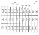
本例の測光センサ137は、二次元カラーCCDイメージセンサなどで構成され、図3Aに示すように複数の矩形状画素137Pが縦横に配列されてなる。図3Aは測光センサ137を示す平面図である。一つの画素137Pの表面には3つの矩形状開口部1371(137R,137G,137B)が形成され、それぞれ赤色、緑色、青色の分光感度特性を有する受光素子によって光束を受光する。なお、開口部1371以外の領域1372は光束に対して感度を有しない不感帯領域である。
The
測光センサ137は、受光した光束の輝度に応じた測光信号を画素137Pごと又は所定の画素群ごとにカメラ制御部170へ出力し、撮影の際の撮像素子110の露出値を演算する。また、測光センサ137による画素ごと又は所定の画素群ごとの測光信号は、カメラ制御部170へ出力されて、撮影シーンの解析や認識にも用いられ、輝度や色彩に基づいて焦点調節対象の位置を解析または認識したり、人物撮影や風景撮影などの撮影モードの選択をしたり、各種画像処理に用いられる。
The
図1に戻り、本例のカメラ1はストロボ装置300を備える。ストロボ装置300にはメイン発光部301が設けられ、発光回路で構成されるストロボ駆動部302により発光駆動される。発光量や発光タイミングの制御は、測光センサ137の出力に基づいてカメラ制御部170からの制御信号によって実行される。
Returning to FIG. 1, the camera 1 of this example includes a
ストロボ装置300にはAF補助光発光部303が設けられ、赤色(波長625〜740nm)にピークをもつLEDで構成されている。AF補助光発光部303は、発光回路で構成されるAF補助光駆動部304により発光駆動され、AF補助光を発光させるか否かの判断はカメラ制御部170で行なわれる。
The
たとえば、測光センサ137の出力によりカメラ制御部170が低輝度であると判断した場合や、ラインセンサ161dの出力によりカメラ制御部170が被写体のコントラストが低いと判断した場合は、カメラ制御部170からの制御信号をAF補助光駆動部304へ送出し、AF補助光駆動部304はAF補助光を発光させる。
For example, when the camera control unit 170 determines that the brightness is low due to the output of the
ところで、焦点検出モジュール161により焦点検出操作を行う際に、受光する光束の色によってラインセンサ161dの各受光部161dnにおける感度(受光信号の出力)にバラツキが生じる。
By the way, when the focus detection operation is performed by the
すなわち、焦点検出モジュール161は、フォーカスレンズ211の射出瞳の異なる一対の領域を通る一対の光束をラインセンサ161dで受光することから、図4Aに示すようにフォーカスレンズ211を通過した一対の光束を光線Aと光線Bで代表すると、これら光線A,Bはハーフミラーであるクイックリターンミラー121を通過する際に、異なる入射角α,βで通過することになり、フォーカスレンズ211の上方からの光線Aの入射角αは下方からの光線Bの入射角βに比べて小さくなる(α<β)。
In other words, the
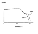
クイックリターンミラー121の分光透過率特性は、図4Bに示すように入射角によって異なり、特に長波長領域における透過率特性の差は短波長領域や中波長領域に比べて大きい。すなわち、青色光線や緑色光線では入射角による透過率の相違は比較的小さいが、赤色光線や近赤外光線は入射角による透過率の相違は大きくなる。したがって、ラインセンサ161dで受光する光束が、特に赤や近赤外である場合には、当該一対のラインセンサ161dのそれぞれの出力(受光信号)を光束の波長に応じて補正する必要性が大きい。なお、ラインセンサ161dで受光する光束が白色光である場合における光線Aと光線Bとの透過率の相違は、図4Bに示す透過率プロファイルを吸収光波長で積分した値となる。
The spectral transmittance characteristic of the
このため、本例のカメラ1は以下の補正処理を実行する。 Therefore, the camera 1 of this example executes the following correction process.
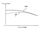
まず、ラインセンサ161dで受光する光束が白色光である場合における、一対のラインセンサ161dそれぞれの受光部161dnの出力は図5Aのようになる。図5Aは、白色光源においてラインセンサ161dの位置(各受光部161dn)に対する出力を示したグラフである。このケースでは、絞り装置220や撮像素子110の調整誤差やフォーカスレンズ211の影響によって各ラインセンサ161dの中心から両端に向かうにしたがって出力が小さくなる。また、光線Aと光線Bについては左右対称のプロファイルを示す。
First, when the light beam received by the
図5Aに示すラインセンサ161dの各受光部161dnの出力を、図5Bに示すように均一に補正するために、本例ではカメラ制御部170の内蔵メモリに白色光源用補正係数を記憶させている。図5Bは補正処理後のラインセンサの各受光部の出力を示すグラフである。
In this example, the white light source correction coefficient is stored in the built-in memory of the camera control unit 170 in order to uniformly correct the output of each light receiving unit 161dn of the
この白色光源用補正係数は、一対の光線A,Bごと、かつ各ラインセンサ161dの受光部161dnごとに決定された値である。そして、光線Aに対する白色光源用補正係数をWPAi、光線Bに対する白色光源用補正係数をWPBi、受光部161dnの数をn個、光線Aを受光するラインセンサの各受光部161dの出力をRAi、光線Bを受光するラインセンサの各受光部161dの出力をRBi、光線Aを受光するラインセンサの各受光部161dの補正後の出力をOutAi、光線Bを受光するラインセンサの各受光部161dの補正後の出力をOutBiとすると、カメラ制御部170は、下記式1の演算を実行し、図5Bに示すように各受光部161dnの出力を均一に補正する。
The white light source correction coefficient is a value determined for each of the pair of light beams A and B and for each light receiving portion 161dn of each
《式1》
OutAi=RAi×WPAi
OutBi=RBi×WPBi
(ただし、i=1〜nの自然数である。)
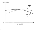
これに対し、ラインセンサ161dで受光する光束が赤色、近赤外、青色などの単色光である場合における、一対のラインセンサ161dそれぞれの受光部161dnの出力は図5Cのようになる。図5Cは、単色光源においてラインセンサ161dの位置(各受光部161dn)に対する出力を示したグラフである。このケースでは、絞り装置220や撮像素子110の調整誤差やフォーカスレンズ211の影響に加え、単色光源の波長よって各ラインセンサ161dの中心から両端に向かうにしたがって出力が小さくなり、図5Aに比べて歪が大きい。また、光線Aと光線Bについては左右対称のプロファイルを示す。
<< Formula 1 >>
OutAi = RAi × WPAi
OutBi = RBi × WPBi
(However, i = 1 to n is a natural number.)
On the other hand, when the light beam received by the
図5Cに示すラインセンサ161dの各受光部161dnの出力を、上述した白色光源用補正係数で補正処理すると、図5Dに示すようになる。すなわち、単色光源の波長による歪に相当する補正残差が生じる。そこで、本例のカメラ1においては、この補正残差を含めた誤差を補正するために、カメラ制御部170の内蔵メモリに単色光源用補正係数を記憶させている。
When the output of each light receiving portion 161dn of the
この単色光源用補正係数は、単色光源の波長ごと、一対の光線A,Bごと、かつ各ラインセンサ161dの受光部161dnごとに決定された値である。そして、光線Aに対する特定(たとえば赤色)の単色光源用補正係数をRedPAi、光線Bに対する赤色光源用補正係数をRedPBi、受光部161dnの数をn個、光線Aを受光するラインセンサの各受光部161dの出力をRAi、光線Bを受光するラインセンサの各受光部161dの出力をRBi、光線Aを受光するラインセンサの各受光部161dの補正後の出力をOutAi、光線Bを受光するラインセンサの各受光部161dの補正後の出力をOutBiとすると、カメラ制御部170は、下記式2の演算を実行し、図5Dに示す補正残差をゼロにするように各受光部161dnの出力を均一に補正する。
The correction coefficient for the monochromatic light source is a value determined for each wavelength of the monochromatic light source, for each pair of light beams A and B, and for each light receiving portion 161dn of each
《式2》
OutAi=RAi×RedPAi
OutBi=RBi×RedPBi
(ただし、i=1〜nの自然数である。)
なお、図5Eは、図5Dの光線Aと光線Bとの、ラインセンサ位置に対する出力の差を示すグラフであり、かかる残差は一次相関となることが知見されているので、式2に代えて、上述した式1の処理を実行したのち、いずれか一方の出力に図5Eに示す残差の傾き係数を用いて補正することもできる。
<< Formula 2 >>
OutAi = RAi × RedPAi
OutBi = RBi × RedPBi
(However, i = 1 to n is a natural number.)
Note that FIG. 5E is a graph showing the output difference between the light beam A and the light beam B in FIG. 5D with respect to the line sensor position, and it has been found that such a residual is a linear correlation. Then, after executing the processing of Equation 1 described above, it is also possible to correct the residual slope coefficient shown in FIG. 5E for one of the outputs.
次に、本例のカメラのAF動作を説明する。 Next, the AF operation of the camera of this example will be described.
図6は、本例のカメラ1のAF動作例を示すフローチャートである。まず、操作部150のレリーズボタンが半押しされると焦点検出制御が開始され、図3Bに示すいずれかの焦点検出エリア1352に相当する焦点検出モジュール161のラインセンサ161dに予備蓄積がされたのち(ステップS1)、予備蓄積された電荷を出力し、この出力レベルが所定値以上であるか否かを判定する(ステップS3)。
FIG. 6 is a flowchart showing an AF operation example of the camera 1 of this example. First, when the release button of the
出力レベルが低く被写体のコントラストが低いと適切な焦点検出ができないので、出力レベルが所定値未満の場合はステップS3へ進んでAF補助光を発光させる。この制御信号は、カメラ制御部170からAF補助光駆動部304へ送出され、AF補助光駆動部304によりAF補助光が発光する。 If the output level is low and the contrast of the subject is low, proper focus detection cannot be performed. If the output level is less than the predetermined value, the process proceeds to step S3 to emit AF auxiliary light. This control signal is sent from the camera control unit 170 to the AF auxiliary light driving unit 304, and the AF auxiliary light driving unit 304 emits AF auxiliary light.
なお、ステップS2において出力レベルが所定値以上であるときはAF補助光を発光させる必要がないことからステップS3をジャンプしてステップS4へ進む。 When the output level is equal to or higher than the predetermined value in step S2, it is not necessary to emit the AF auxiliary light, so step S3 is jumped and the process proceeds to step S4.
ステップS4では、AF補助光が発光しているか否かを判定する。AF補助光が発光しているか否かは、カメラ制御部170からAF補助光駆動部304へ送出される制御信号の有無により判定することができる。 In step S4, it is determined whether or not AF auxiliary light is emitted. Whether or not AF auxiliary light is emitted can be determined by the presence or absence of a control signal sent from the camera control unit 170 to the AF auxiliary light driving unit 304.
そして、AF補助光が発光している場合はステップS5へ進み、AF補助光が発光していない場合はステップS6へ進む。 If the AF auxiliary light is emitted, the process proceeds to step S5. If the AF auxiliary light is not emitted, the process proceeds to step S6.
ステップS5では、ラインセンサ161dの各受光部161dnの出力を補正するための補正係数を単色光源用補正係数RedPAi,RedPBiに設定する。なお、本例のAF補助光発光部303は赤色LEDで構成されているので、補正係数は赤色光源に対応した補正係数とする。
In step S5, the correction coefficient for correcting the output of each light receiving part 161dn of the
これに対し、ステップS6では、ラインセンサ161dの各受光部161dnの出力を補正するための補正係数を白色光源用補正係数WPAi,WPBiに設定する。AF補助光が発光していないので、ラインセンサ161dで受光する光束は白色光となるからである。
On the other hand, in step S6, the correction coefficient for correcting the output of each light receiving unit 161dn of the
ステップS7では、実際のAF操作を実行するために、選択された図3Bに示すいずれかの焦点検出エリア1352に相当するラインセンサ161dに電荷を蓄積し、AF−CCD制御部162へ各受光部161dnの電荷を出力する。この出力がRAi,RBi(i=1〜nの自然数)である。
In step S7, in order to execute the actual AF operation, charges are accumulated in the selected
ステップS8では、ステップS5またはS6で設定された補正係数に基づいて、ラインセンサ161dの各受光部161dnの出力を補正する。すなわち、ステップS5により赤色光源用補正係数が設定された場合は、上述した式2に基づいて出力を補正し、ステップS6により白色光源用補正係数が設定された場合には、上述した式1に基づいて出力を補正する。
In step S8, the output of each light receiving unit 161dn of the
ステップS9では、ステップS8で補正した出力をデフォーカス演算部163へ送出し、デフォーカス演算部163は、この出力(一対の像信号のずれ量に相当)をデフォーカス量ΔWに変換し、これをレンズ駆動量演算部164へ出力する。 In step S9, the output corrected in step S8 is sent to the defocus calculation unit 163, and the defocus calculation unit 163 converts this output (corresponding to the shift amount of the pair of image signals) into the defocus amount ΔW, Is output to the lens driving amount calculation unit 164.
レンズ駆動量演算部164は、デフォーカス演算部163から送られてきたデフォーカス量ΔWに基づいて、当該デフォーカス量ΔWに応じたレンズ駆動量Δdを演算し、これをレンズ駆動制御部165へ出力する。 The lens drive amount calculation unit 164 calculates a lens drive amount Δd corresponding to the defocus amount ΔW based on the defocus amount ΔW sent from the defocus calculation unit 163, and supplies this to the lens drive control unit 165. Output.
ステップS10では、レンズ駆動制御部165は、レンズ駆動量演算部164から送られてきたレンズ駆動量Δdに基づいてレンズ駆動モータ230へ駆動指令を送出し、レンズ駆動量Δdだけフォーカスレンズ211を移動させる。
In step S10, the lens drive control unit 165 sends a drive command to the lens drive motor 230 based on the lens drive amount Δd sent from the lens drive amount calculation unit 164, and moves the
ステップS11では、フォーカスレンズ211の移動後の焦点検出操作を実行し、所定の閾値以内の場合は合焦と判定してAF操作を終了するが、所定の閾値以内にない場合はステップS1へ戻って以上の操作を繰り返す。
In step S11, the focus detection operation after the movement of the
以上のように、本例のカメラ1によれば、ラインセンサ161dの各受光部161dnの出力の補正係数を、赤色光源であるAF補助光が発光している場合は赤色光源用補正係数に設定し、AF補助光が発光せず白色光源の場合は白色光源用補正係数に設定するので、色の相違によって受光部161dnの出力を適切な値に補正することができる。
As described above, according to the camera 1 of this example, the correction coefficient of the output of each light receiving unit 161dn of the
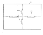
特に図3Bに示すファインダ画面1351に設定された複数の焦点検出エリア1352のうち、縦方向に設定された焦点検出エリア1352Aは、光線Aと光線Bとのクイックリターンミラー121に対する入射角α,βに差が生じることから、横方向に設定された焦点検出エリア1352に比べ、色の相違による補正効果が大きくなる。
In particular, among the plurality of
図7は、本例のカメラ1の他のAF動作例を示すフローチャートである。 FIG. 7 is a flowchart showing another AF operation example of the camera 1 of this example.
図6に示すAF動作例では、カメラ制御部170のメモリに白色光源用補正係数WPAi,WPBiと単色光源用補正係数RedPAi,RedPBiを記憶させ、AF補助光の発光の有無に応じてラインセンサ161dの受光信号出力を補正したが、被写体の色に応じたラインセンサ161dの出力を補正することもできる。
In the AF operation example shown in FIG. 6, the white light source correction coefficients WPAi and WPBi and the monochromatic light source correction coefficients RedPAi and RedPBi are stored in the memory of the camera control unit 170, and the
すなわち、ステップS21では、測光センサ137により検出された被写体の受光信号のうち選択された焦点検出エリア1352に対応する測光センサ137のエリアの受光信号に基づいて、被写体の色を検出する。
That is, in step S21, the color of the subject is detected based on the light reception signal in the area of the
カメラ制御部170には、白色光源用補正係数WPAi,WPBiに代えて、赤色光源用補正係数RedPAi,RedPBiと、青色光源用補正係数BluPAi,BluPBiと、緑色光源用補正係数GrePAi,GrePBiが予め記憶されている。 Instead of the white light source correction coefficients WPAi and WPBi, the camera control unit 170 stores in advance red light source correction coefficients RedPAi and RedPBi, blue light source correction coefficients BluPAi and BluPBi, and green light source correction coefficients GrePAi and GrePBi. Has been.
ステップS22では、ステップS21で検出された被写体の色情報を(r,b,g)としたときに、下記式3により補正係数PAi,PBiを生成する。 In step S22, when the color information of the subject detected in step S21 is (r, b, g), correction coefficients PAi and PBi are generated by the following equation 3.
《式3》
PAi=RedPAi×r+BluPAi×b+GrePAi×g
PBi=RedPBi×r+BluPBi×b+GrePBi×g
ステップS23では、実際のAF操作を実行するために、選択された図3Bに示すいずれかの焦点検出エリア1352に相当するラインセンサ161dに電荷を蓄積し、AF−CCD制御部162へ各受光部161dnの電荷を出力する。この出力がRAi,RBi(i=1〜nの自然数)である。
<< Formula 3 >>
PAi = RedPAi × r + BluPAi × b + GrePAi × g
PBi = RedPBi × r + BluPBi × b + GrePBi × g
In step S23, electric charges are accumulated in the
ステップS24では、ステップS22で生成された補正係数PAi,PBiに基づいて、ラインセンサ161dの各受光部161dnの出力を補正する。
In step S24, the output of each light receiving unit 161dn of the
すなわち、下記式4に基づいて出力を補正する。 That is, the output is corrected based on the following formula 4.
《式4》
OutAi=RAi×PAi
OutBi=RBi×PBi
(ただし、i=1〜nの自然数である。)
ステップS25では、ステップS24で補正した出力をデフォーカス演算部163へ送出し、デフォーカス演算部163は、この出力(一対の像信号のずれ量に相当)をデフォーカス量ΔWに変換し、これをレンズ駆動量演算部164へ出力する。
<< Formula 4 >>
OutAi = RAi × PAi
OutBi = RBi × PBi
(However, i = 1 to n is a natural number.)
In step S25, the output corrected in step S24 is sent to the defocus calculation unit 163, and the defocus calculation unit 163 converts this output (corresponding to the shift amount of the pair of image signals) into a defocus amount ΔW. Is output to the lens driving amount calculation unit 164.
レンズ駆動量演算部164は、デフォーカス演算部163から送られてきたデフォーカス量ΔWに基づいて、当該デフォーカス量ΔWに応じたレンズ駆動量Δdを演算し、これをレンズ駆動制御部165へ出力する。 The lens drive amount calculation unit 164 calculates a lens drive amount Δd corresponding to the defocus amount ΔW based on the defocus amount ΔW sent from the defocus calculation unit 163, and supplies this to the lens drive control unit 165. Output.
ステップS26では、レンズ駆動制御部165は、レンズ駆動量演算部164から送られてきたレンズ駆動量Δdに基づいてレンズ駆動モータ230へ駆動指令を送出し、レンズ駆動量Δdだけフォーカスレンズ211を移動させる。
In step S26, the lens drive control unit 165 sends a drive command to the lens drive motor 230 based on the lens drive amount Δd sent from the lens drive amount calculation unit 164, and moves the
ステップS27では、フォーカスレンズ211の移動後の焦点検出操作を実行し、所定の閾値以内の場合は合焦と判定してAF操作を終了するが、所定の閾値以内にない場合はステップS1へ戻って以上の操作を繰り返す。
In step S27, the focus detection operation after the movement of the
以上のように、本例のカメラ1によれば、ラインセンサ161dの各受光部161dnの出力の補正係数を被写体の色に応じた補正係数に設定するので、色の相違によって受光部161dnの出力を適切な値に補正することができる。
As described above, according to the camera 1 of the present example, the correction coefficient of the output of each light receiving unit 161dn of the
なお、さらに他のAF動作例として、図6に示すステップS6に代えて図7に示すステップS21〜S22を実行することもできる。 As still another AF operation example, steps S21 to S22 shown in FIG. 7 can be executed instead of step S6 shown in FIG.
また、レリーズ動作にともなって、クイックリターンミラー121の角度が経時変化し、光線A,Bの入射角が図4Aに示す状態から変化することがある。この場合は、たとえばレリーズ回数10万回につきミラーが0.1度変化するとして、この角度変化に応じた補正係数を記憶しておき、レリーズ回数に応じた補正係数に応じて補正するようにしてもよい。
Further, with the release operation, the angle of the
1…一眼レフデジタルカメラ
100…カメラボディ
110…撮像素子
131…焦点板
136…測光用レンズ
137…測光センサ
138…絞り
161…焦点検出モジュール
161d…ラインセンサ
161dn…受光部
170…カメラ制御部
200…レンズ鏡筒
210…レンズ群
220…絞り装置
230…レンズ駆動モータ
240…絞り駆動装置
250…レンズ制御部
300…ストロボ装置
301…メイン発光部
302…ストロボ駆動部
303…AF補助光発光部
304…AF補助光駆動部
DESCRIPTION OF SYMBOLS 1 ... Single-lens reflex
Claims (11)
前記複数の受光部の位置に応じた第1補正値、及び、前記複数の受光部の位置に応じた、前記第1補正値とは異なる第2補正値を記憶する記憶手段と、
前記受光手段により受光される前記光束の色が第1色であるか、第2色であるかを判断する判断部と、
前記受光手段により受光される前記光束の色が前記第1色であると前記判断部により判断されたとき、前記第1補正値を用いて前記受光信号を補正し、前記受光手段により受光される前記光束の色が前記第2色であると前記判断部により判断されたとき、前記第1補正値及び前記第2補正値を用いて前記受光信号を補正する補正手段と、
前記補正手段により補正された前記一対の受光信号の相関を演算することで、前記光学系の焦点調節状態を検出する焦点検出手段と、
前記焦点検出手段による焦点検出結果に応じて、焦点調節光学系の駆動を制御する制御手段と、を備えることを特徴とする焦点検出装置。 A plurality of light receiving portions, respectively, and a pair of light receiving means for outputting a pair of light receiving signal by receiving the light beam,
Storage means for storing a first correction value according to the positions of the plurality of light receiving units and a second correction value different from the first correction value according to the positions of the plurality of light receiving units ;
A determination unit for determining whether the color of the light beam received by the light receiving unit is a first color or a second color;
When the determination unit determines that the color of the light beam received by the light receiving unit is the first color, the light receiving signal is corrected using the first correction value and received by the light receiving unit. Correction means for correcting the received light signal using the first correction value and the second correction value when the determination unit determines that the color of the luminous flux is the second color;
A focus detection unit that detects a focus adjustment state of the optical system by calculating a correlation between the pair of light reception signals corrected by the correction unit;
A focus detection apparatus comprising: control means for controlling driving of the focus adjustment optical system according to a focus detection result by the focus detection means .
前記第1補正値は、白色光源の光束に対する白色光源用補正値であり、The first correction value is a white light source correction value for a light beam of a white light source,
前記第2補正値は、単色光源の光束の波長に起因して生じる前記一対の受光信号間の出力差に対応する傾き係数であることを特徴とする焦点検出装置。The focus correction apparatus, wherein the second correction value is an inclination coefficient corresponding to an output difference between the pair of received light signals caused by a wavelength of a light beam of a monochromatic light source.
前記補正手段は、前記受光手段により受光される前記光束の色が前記第2色であると前記判断部により判断されたとき、前記白色光源用補正値を用いて前記一対の受光信号を補正した後に、前記傾き係数を用いて補正した前記一対の受光信号のうちいずれか一方を補正することを特徴とする焦点検出装置。The correction unit corrects the pair of light reception signals using the correction value for the white light source when the determination unit determines that the color of the light beam received by the light reception unit is the second color. A focus detection apparatus that corrects either one of the pair of received light signals corrected by using the inclination coefficient later.
前記複数の受光部の位置に応じた第1補正値、及び、前記複数の受光部の位置に応じた前記第1補正値とは異なる第2補正値を記憶する記憶手段と、Storage means for storing a first correction value according to the positions of the plurality of light receiving units and a second correction value different from the first correction value according to the positions of the plurality of light receiving units;
前記受光手段により受光される前記光束の色が第1色であるか、第2色であるかを判断する判断部と、A determination unit for determining whether the color of the light beam received by the light receiving unit is a first color or a second color;
前記受光手段により受光される前記光束の色が前記第1色であると前記判断部により判断されたとき、前記第1補正値を用いて前記受光信号を補正し、前記受光手段により受光される前記光束の色が前記第2色であると前記判断部により判断されたとき、前記第2補正値を用いて前記受光信号を補正する補正手段と、When the determination unit determines that the color of the light beam received by the light receiving unit is the first color, the light receiving signal is corrected using the first correction value and received by the light receiving unit. Correction means for correcting the light reception signal using the second correction value when the determination unit determines that the color of the light beam is the second color;
前記補正手段により補正された前記一対の受光信号の相関を演算することで、前記光学系の焦点調節状態を検出する焦点検出手段と、A focus detection unit that detects a focus adjustment state of the optical system by calculating a correlation between the pair of light reception signals corrected by the correction unit;
前記焦点検出手段による焦点検出結果に応じて、焦点調節光学系の駆動を制御する制御手段と、を備えることを特徴とする焦点検出装置。A focus detection apparatus comprising: control means for controlling driving of the focus adjustment optical system according to a focus detection result by the focus detection means.
前記第1補正値は、白色光源による光束に対する白色光源用補正値であり、
前記第2補正値は、単色光源による光束に対する単色光源用補正値であり、
前記受光手段により受光される前記光束が白色であると前記判断部により判断されたとき、前記第1補正値を用いて前記受光信号を補正し、前記受光手段により受光される前記光束が単色であると前記判断部により判断されたとき、前記第2補正値を用いて前記受光信号を補正することを特徴とする焦点検出装置。 The focus detection apparatus according to claim 4,
The first correction value is a correction value for a white light source with respect to a light beam by a white light source,
The second correction value is a correction value for a monochromatic light source with respect to a light beam by a monochromatic light source,
When the determination unit determines that the light beam received by the light receiving unit is white, the light reception signal is corrected using the first correction value, and the light beam received by the light receiving unit is monochromatic. A focus detection apparatus that corrects the light reception signal using the second correction value when the determination unit determines that there is .
被写体に対して単色光を照射する照射手段を備え、An irradiation means for irradiating the subject with monochromatic light;
前記判断部は、前記照射手段による照射が行われていない場合には、前記受光手段により受光される前記光束が白色であると判断し、前記照射手段による照射が行われた場合には、前記受光手段により受光される前記光束が単色であると判断することを特徴とする焦点検出装置。The determination unit determines that the light beam received by the light receiving unit is white when irradiation by the irradiation unit is not performed, and when irradiation by the irradiation unit is performed, A focus detection apparatus, wherein the light beam received by the light receiving means is determined to be monochromatic.
前記焦点検出手段は、前記光学系による画面内に設定された焦点検出位置に対する前記焦点調節状態を検出し、
前記光学系による像のうち、前記焦点検出位置に対応する像の色を検出する色検出手段をさらに備え、
前記補正手段は、前記色検出手段により検出された色に応じた補正値により前記受光信号を補正することを特徴とする焦点検出装置。 In the focus detection apparatus according to any one of claims 1 to 6 ,
The focus detection means detects the focus adjustment state with respect to a focus detection position set in the screen by the optical system,
Color detection means for detecting the color of the image corresponding to the focus detection position among the images by the optical system,
The focus detection apparatus, wherein the correction unit corrects the light reception signal with a correction value corresponding to the color detected by the color detection unit.
前記受光手段は、前記光学系を介した一対の光束を受光するものであり、
前記光学系と前記受光手段との間の前記光束の光路中に設けられた、前記一対の光束が入射する光学部品を備え、
前記補正手段は、前記光学部品に対する前記一対の光束の入射角が互いに異なる場合に、前記受光信号を補正することを特徴とする焦点検出装置。 In the focus detection apparatus according to any one of claims 1 to 7 ,
The light receiving means receives a pair of light beams via the optical system,
An optical component provided in the optical path of the light beam between the optical system and the light receiving means, on which the pair of light beams are incident;
The focus detection apparatus, wherein the correction unit corrects the light reception signal when incident angles of the pair of light beams with respect to the optical component are different from each other.
被写体に対して光を照射する照射手段を備え、
前記補正手段は、前記光の照射に応じて前記受光信号を補正することを特徴とする撮像装置。 The imaging device according to claim 9 ,
An irradiation means for irradiating the subject with light;
The image pickup apparatus, wherein the correction unit corrects the light reception signal in accordance with the light irradiation.
被写体の色を検出する色検出手段を備え、
前記補正手段は、前記色検出手段により検出された色に応じて前記受光信号を補正することを特徴とする撮像装置。 The imaging device according to claim 9 ,
Color detecting means for detecting the color of the subject;
The image pickup apparatus, wherein the correction unit corrects the light reception signal in accordance with the color detected by the color detection unit.
Priority Applications (1)
| Application Number | Priority Date | Filing Date | Title |
|---|---|---|---|
| JP2008128348A JP5115324B2 (en) | 2008-05-15 | 2008-05-15 | Focus detection apparatus and imaging apparatus |
Applications Claiming Priority (1)
| Application Number | Priority Date | Filing Date | Title |
|---|---|---|---|
| JP2008128348A JP5115324B2 (en) | 2008-05-15 | 2008-05-15 | Focus detection apparatus and imaging apparatus |
Publications (2)
| Publication Number | Publication Date |
|---|---|
| JP2009276605A JP2009276605A (en) | 2009-11-26 |
| JP5115324B2 true JP5115324B2 (en) | 2013-01-09 |
Family
ID=41442097
Family Applications (1)
| Application Number | Title | Priority Date | Filing Date |
|---|---|---|---|
| JP2008128348A Expired - Fee Related JP5115324B2 (en) | 2008-05-15 | 2008-05-15 | Focus detection apparatus and imaging apparatus |
Country Status (1)
| Country | Link |
|---|---|
| JP (1) | JP5115324B2 (en) |
Families Citing this family (1)
| Publication number | Priority date | Publication date | Assignee | Title |
|---|---|---|---|---|
| JP7585150B2 (en) * | 2020-07-30 | 2024-11-18 | オリンパス株式会社 | IMAGING APPARATUS, METHOD FOR EXECUTING PHASE-DIFFERENCE AUTOFOCUS, ENDOSCOPYRIGHT SYSTEM, AND PROGRAM |
Family Cites Families (6)
| Publication number | Priority date | Publication date | Assignee | Title |
|---|---|---|---|---|
| JPS59116604A (en) * | 1982-11-22 | 1984-07-05 | Olympus Optical Co Ltd | Focus detection |
| JPS62174710A (en) * | 1986-01-28 | 1987-07-31 | Minolta Camera Co Ltd | Focus detecting device |
| JP2643326B2 (en) * | 1988-07-07 | 1997-08-20 | キヤノン株式会社 | Single-lens reflex camera with focus detection device |
| JPH05134169A (en) * | 1991-11-12 | 1993-05-28 | Olympus Optical Co Ltd | Focal point detecting device |
| JP4504031B2 (en) * | 2004-01-22 | 2010-07-14 | オリンパス株式会社 | Camera system |
| JP2007140305A (en) * | 2005-11-21 | 2007-06-07 | Canon Inc | Imaging device |
-
2008
- 2008-05-15 JP JP2008128348A patent/JP5115324B2/en not_active Expired - Fee Related
Also Published As
| Publication number | Publication date |
|---|---|
| JP2009276605A (en) | 2009-11-26 |
Similar Documents
| Publication | Publication Date | Title |
|---|---|---|
| US7936986B2 (en) | Image pickup apparatus control method thereof and image pickup system | |
| JP2010197551A (en) | Imaging apparatus and image synthesis method | |
| JP5168798B2 (en) | Focus adjustment device and imaging device | |
| JP5168797B2 (en) | Imaging device | |
| JP2007233032A (en) | Focus adjustment device and imaging device | |
| JP5966299B2 (en) | FOCUS DETECTION DEVICE AND IMAGING DEVICE HAVING THE SAME | |
| JP5115324B2 (en) | Focus detection apparatus and imaging apparatus | |
| JP5256847B2 (en) | Imaging device | |
| JP5309661B2 (en) | Exposure calculation device and imaging device | |
| JP2009205061A (en) | Lens driving device and imaging apparatus | |
| JP5458860B2 (en) | Imaging device | |
| JP5803065B2 (en) | Focus detection apparatus and imaging apparatus | |
| JP6699679B2 (en) | Imaging device | |
| JP5391587B2 (en) | Imaging device | |
| JP4865275B2 (en) | Focus detection apparatus and imaging apparatus | |
| JP4532169B2 (en) | Focus detection device | |
| JP5493470B2 (en) | Focus adjustment device and imaging device provided with the same | |
| JP6503625B2 (en) | Image pickup device and image pickup apparatus provided with the same | |
| JP5407310B2 (en) | FOCUS DETECTION DEVICE AND IMAGING DEVICE HAVING THE SAME | |
| JP4928236B2 (en) | Imaging apparatus and imaging system | |
| JP5115325B2 (en) | Lens barrel and imaging device | |
| JP4541808B2 (en) | Imaging apparatus and imaging system | |
| JP6391448B2 (en) | Imaging apparatus and control method thereof | |
| JP2013054288A (en) | Focus detecting device and imaging apparatus | |
| JP2019053315A (en) | Focus adjustment device and imaging device |
Legal Events
| Date | Code | Title | Description |
|---|---|---|---|
| A621 | Written request for application examination |
Free format text: JAPANESE INTERMEDIATE CODE: A621 Effective date: 20110331 |
|
| A521 | Request for written amendment filed |
Free format text: JAPANESE INTERMEDIATE CODE: A523 Effective date: 20110921 |
|
| A977 | Report on retrieval |
Free format text: JAPANESE INTERMEDIATE CODE: A971007 Effective date: 20120305 |
|
| A131 | Notification of reasons for refusal |
Free format text: JAPANESE INTERMEDIATE CODE: A131 Effective date: 20120313 |
|
| A521 | Request for written amendment filed |
Free format text: JAPANESE INTERMEDIATE CODE: A523 Effective date: 20120514 |
|
| TRDD | Decision of grant or rejection written | ||
| A01 | Written decision to grant a patent or to grant a registration (utility model) |
Free format text: JAPANESE INTERMEDIATE CODE: A01 Effective date: 20120918 |
|
| A01 | Written decision to grant a patent or to grant a registration (utility model) |
Free format text: JAPANESE INTERMEDIATE CODE: A01 |
|
| A61 | First payment of annual fees (during grant procedure) |
Free format text: JAPANESE INTERMEDIATE CODE: A61 Effective date: 20121001 |
|
| R150 | Certificate of patent or registration of utility model |
Free format text: JAPANESE INTERMEDIATE CODE: R150 Ref document number: 5115324 Country of ref document: JP Free format text: JAPANESE INTERMEDIATE CODE: R150 |
|
| FPAY | Renewal fee payment (event date is renewal date of database) |
Free format text: PAYMENT UNTIL: 20151026 Year of fee payment: 3 |
|
| FPAY | Renewal fee payment (event date is renewal date of database) |
Free format text: PAYMENT UNTIL: 20151026 Year of fee payment: 3 |
|
| R250 | Receipt of annual fees |
Free format text: JAPANESE INTERMEDIATE CODE: R250 |
|
| R250 | Receipt of annual fees |
Free format text: JAPANESE INTERMEDIATE CODE: R250 |
|
| R250 | Receipt of annual fees |
Free format text: JAPANESE INTERMEDIATE CODE: R250 |
|
| R250 | Receipt of annual fees |
Free format text: JAPANESE INTERMEDIATE CODE: R250 |
|
| R250 | Receipt of annual fees |
Free format text: JAPANESE INTERMEDIATE CODE: R250 |
|
| R250 | Receipt of annual fees |
Free format text: JAPANESE INTERMEDIATE CODE: R250 |
|
| LAPS | Cancellation because of no payment of annual fees |