JP5115731B2 - Imaging apparatus, image processing method, and program - Google Patents
Imaging apparatus, image processing method, and program Download PDFInfo
- Publication number
- JP5115731B2 JP5115731B2 JP2008191230A JP2008191230A JP5115731B2 JP 5115731 B2 JP5115731 B2 JP 5115731B2 JP 2008191230 A JP2008191230 A JP 2008191230A JP 2008191230 A JP2008191230 A JP 2008191230A JP 5115731 B2 JP5115731 B2 JP 5115731B2
- Authority
- JP
- Japan
- Prior art keywords
- image
- imaging
- shooting
- images
- angular velocity
- Prior art date
- Legal status (The legal status is an assumption and is not a legal conclusion. Google has not performed a legal analysis and makes no representation as to the accuracy of the status listed.)
- Active
Links
Images


Landscapes
- Studio Devices (AREA)
Description
本発明は、画像劣化を生じさせずに高速でパノラマ画像の生成を可能とする撮像装置及び画像処理方法並びにプログラムに関する。 The present invention relates to an imaging apparatus, an image processing method, and a program capable of generating a panoramic image at high speed without causing image degradation.
画角の広いパノラマ画像を作成するためには、円柱状に画像を投影する必要がある。従来のパノラマ画像の作成方法として、例えば、スイングレンズ式カメラと呼ばれるパノラマ撮影専用の特殊なカメラを用いて、円筒面に被写体像を撮影してパノラマ画像を合成する方法が提案されている。しかし、このスイングレンズ式カメラは、価格が高いという欠点がある。 In order to create a panoramic image with a wide angle of view, it is necessary to project the image in a cylindrical shape. As a conventional method of creating a panoramic image, for example, a method of synthesizing a panoramic image by photographing a subject image on a cylindrical surface using a special camera dedicated to panoramic photographing called a swing lens type camera has been proposed. However, this swing lens type camera has a drawback that it is expensive.
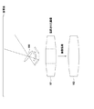
そこで、特殊なカメラを使わずに複数回撮影することでパノラマ画像を合成するパノラマ撮影モードを有するデジタルスチルカメラが提案されている。このデジタルスチルカメラにおいては、例えば図6に示すように、カメラを回転させながら撮影範囲を少しずつ重ねて複数回撮影を行い、撮影した複数の画像を画像処理によりつなぎ合わせることでパノラマ画像を合成する。 Therefore, a digital still camera having a panoramic shooting mode in which panoramic images are synthesized by shooting a plurality of times without using a special camera has been proposed. In this digital still camera, as shown in FIG. 6, for example, while rotating the camera, the shooting range is gradually overlapped and shot several times, and the shot images are combined by image processing to synthesize a panoramic image. To do.
具体的に、図6に示す方法では、レンズ100から入射される被写体像に基づく複数の画像を撮影し、撮影した複数の画像を重ね合わせることで合成画像101を作成する。しかし、この図6に示す方法で合成される合成画像101は、多角形状に投影されるため、撮影した複数の画像をそのまま並べただけでは像が折れ曲がってしまい、画像の繋ぎ目が滑らかに結合しない。換言すると、図6に示す方法では、平面に撮影された画像同士を繋ぎ合わせるため、画像の繋ぎ目部分で急に折れ曲がった不連続な画像となってしまう。そこで、図6に示す方法では、例えば撮影された画像に対して画像処理を行い合成することで、繋ぎ目が滑らかなパノラマ画像102を生成する。
Specifically, in the method illustrated in FIG. 6, a plurality of images based on the subject image incident from the
しかしながら、図6に示す方法では、上述したように撮影された画像に対して画像処理を施すため時間を要し、高速でパノラマ画像を作成するのが困難となるため、撮影終了後すぐに作成したパノラマ画像を鑑賞することができない。また、図6に示す方法では、撮影された画像に画像処理を施すため、この画像処理に伴って補正後のパノラマ画像102に画像劣化が生じてしまう虞がある。
However, in the method shown in FIG. 6, it takes time to perform image processing on the image captured as described above, and it is difficult to create a panoramic image at high speed. Can't view the panorama image Further, in the method shown in FIG. 6, since image processing is performed on the photographed image, there is a possibility that image degradation occurs in the corrected
本発明では、上記従来の課題を解決するものであり、パノラマ画像に劣化を生じさせずに、高速にパノラマ画像の合成を可能とする撮像装置及び画像処理方法並びにプログラムを提供することを目的とする。 An object of the present invention is to solve the above-described conventional problems, and to provide an imaging apparatus, an image processing method, and a program capable of combining panoramic images at high speed without causing deterioration of the panoramic images. To do.
すなわち、本発明に係る撮像装置は、レンズから入射される被写体像を撮像面に撮像する撮像部と、当該撮像装置の動きに基づいて、撮影開始位置に対する相対的な角度を検出する角度検出部と、上記撮像部の撮像面に撮像された第1の画像の一部を構成するスリット状の短手方向の長さWの第2の画像を上記撮像面の中央部分から読み出し、当該読み出した複数の第2の画像と、当該複数の第2の画像それぞれに対応する上記撮影開始位置に対する相対的な角度とに基づいて、パノラマ画像を合成する制御部とを備え、上記制御部は、当該撮像装置の動きに基づいて、上記第2の画像を読み出す際の上記長さW又は上記撮像部の連写速度を制御する。 That is, an imaging device according to the present invention includes an imaging unit that captures a subject image incident from a lens on an imaging surface, and an angle detection unit that detects a relative angle with respect to a shooting start position based on the movement of the imaging device. And reading a second image having a slit-like length W in the lateral direction that forms part of the first image picked up on the image pickup surface of the image pickup unit from the center portion of the image pickup surface . A control unit configured to synthesize a panoramic image based on a plurality of second images and a relative angle with respect to the shooting start position corresponding to each of the plurality of second images, and the control unit includes: Based on the movement of the imaging device, the length W when reading the second image or the continuous shooting speed of the imaging unit is controlled.
また、本発明に係る画像処理方法は、レンズから入射される被写体像を撮像面に撮像する撮像工程と、撮像装置の動きに基づいて、撮影開始に対する相対的な角度を角度検出部により検出する角度検出工程と、上記撮像面に撮像された第1の画像の一部を構成するスリット状の短手方向の長さWの第2の画像を上記撮像面の中央部分から読み出す読み出し工程と、複数の上記第2の画像と当該複数の第2の画像それぞれに対応する上記撮影開始位置に対する相対的な角度とに基づいて、パノラマ画像を合成する合成工程とを有し、上記読み出し工程では、上記撮像装置の動きに基づいて、上記第2の画像を読み出す際の上記長さW又は上記撮像部の連写速度を制御する。 In addition, the image processing method according to the present invention detects, by the angle detection unit, a relative angle with respect to the start of imaging based on an imaging process of imaging a subject image incident from a lens on an imaging surface and movement of the imaging device. An angle detection step, and a reading step of reading out from the center portion of the imaging surface a second image having a length W in the short-side direction that forms a part of the first image imaged on the imaging surface ; A synthesis step of synthesizing a panoramic image based on a plurality of the second images and a relative angle with respect to the shooting start position corresponding to each of the plurality of second images, and in the reading step, Based on the movement of the imaging device, the length W when reading the second image or the continuous shooting speed of the imaging unit is controlled.
また、本発明に係るプログラムは、レンズから入射される被写体像を撮像面に撮像する撮像工程と、撮像装置の動きに基づいて、撮影開始に対する相対的な角度を角度検出部により検出する角度検出工程と、上記撮像面に撮像された第1の画像の一部を構成するスリット状の短手方向の長さWの第2の画像を上記撮像面の中央部分から読み出す読み出し工程と、複数の上記第2の画像と当該複数の第2の画像それぞれに対応する上記撮影開始位置に対する相対的な角度とに基づいて、パノラマ画像を合成する合成工程とを有し、上記読み出し工程では、上記撮像装置の動きに基づいて、上記第2の画像を読み出す際の上記長さW又は上記撮像部の連写速度を制御する処理をコンピュータに実行させるためのものである。 In addition, the program according to the present invention includes an imaging process for imaging a subject image incident from a lens on an imaging surface, and an angle detection for detecting a relative angle with respect to a shooting start by an angle detection unit based on the movement of the imaging device. A step of reading out a second image having a length W in the short direction of the slit, which forms a part of the first image captured on the imaging surface, from a central portion of the imaging surface, and a plurality of steps A synthesis step of synthesizing a panoramic image based on the second image and a relative angle with respect to the shooting start position corresponding to each of the plurality of second images, and in the reading step, the imaging This is for causing the computer to execute processing for controlling the length W or the continuous shooting speed of the imaging unit when reading the second image based on the movement of the apparatus.
本発明によれば、撮像装置の動きに応じて第2の画像のスリット状の短手方向の長さW又は連写速度を制御することにより、画像の繋ぎ目が滑らかなパノラマ画像を合成することができる。したがって、本発明によれば、画像を滑らかにするための画像処理が不要となるため、画像処理に伴った画像の劣化を生じさせずに、高速にパノラマ画像を合成することが可能となる。 According to the present invention, a panoramic image with smooth joints between images is synthesized by controlling the slit-like length W of the second image or the continuous shooting speed in accordance with the movement of the imaging device. be able to. Therefore, according to the present invention, it is not necessary to perform image processing for smoothing the image, so that it is possible to synthesize a panoramic image at high speed without causing image degradation due to image processing.
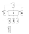
以下、図面を参照しながら、本発明を適用した具体的な実施形態について説明する。図1に示すように、本発明を適用した撮像装置1は、固体撮像素子10と、AFE(アナログフロントエンド回路)11と、制御部12と、角速度センサ13と、スイッチ14と、マイコン15と、メモリ16と、記録媒体17と、操作部18とを備える。撮像装置1においては、撮像装置1の動きとして角速度センサ13による角速度値を検出し、検出した角速度値に応じて、固体撮像素子10の撮像面に撮像された第1の画像の一部を構成するスリット状の短手方向の長さWの第2の画像の長さW又は連写速度を制御する。そして、撮像装置1においては、固体撮像素子10から読み出した複数の第2の画像と、第2の画像それぞれに対応する撮影開始位置に対する相対的な角度とに基づいて、パノラマ画像を合成する。これにより、撮像装置1においては、パノラマ画像を合成する際に必要な画像処理が不要となり、パノラマ画像に劣化を生じさせずに、高速に画像の繋ぎ目が滑らかなパノラマ画像を合成することが可能となる。
Hereinafter, specific embodiments to which the present invention is applied will be described with reference to the drawings. As shown in FIG. 1, an
固体撮像素子10は、例えばCCD(Charge Coupled Device)やCMOS(Complementary Metal Oxide Semiconductor)で構成され、図示しないレンズから入射される被写体像を電気信号に変換(光電変換)して撮像信号を生成する。そして、固体撮像素子10は、電気信号に変換された撮像信号をAFE11に供給する。本実施形態では、後に詳述するように高速連写や撮像面の一部分からの高速な画像の読み出しを可能とするために、固体撮像素子10をCMOSで構成するのが好ましい。
The solid-
AFE11は、固体撮像素子10のアナログフロントエンド回路であり、固体撮像素子10から供給される撮像信号に対してアナログ処理(自動利得制御)や雑音除去処理を行う。そして、AFE11により処理された撮像信号は、A/D変換回路(図示せず)によりデジタル信号に変換され、制御部12に供給される。
The AFE 11 is an analog front-end circuit of the solid-
制御部12は、例えばASIC(Application Specific Integrated Circuit)やMPU(Micro Processor Unit)で構成され、A/D変換回路から供給されたデジタル信号に対して画像処理を行う。制御部12は、例えば画像処理として、ホワイトバランス処理、エッジ強調処理、JPEG規格のデータ圧縮・伸長等を行う。そして制御部12は、画像処理後の画像信号をメモリ16や記録媒体17に供給する。また、制御部12は、操作部18からの操作信号に基づいて、通常撮影時の第1のモードとパノラマ撮影時の第2のモードとを切り替える。
The
角速度センサ13は、例えば通常手ぶれ補正のために用いられるジャイロセンサで構成され、撮像装置1が動いたときの角速度を検出する。角速度センサ13は、例えばパノラマ撮影モード時には、撮像装置1の動きに基づく撮影開始から撮影終了までの角速度値を検出し、この検出した角速度値をスイッチ14を介して制御部12及びマイコン15に供給する。
The
スイッチ14では、制御部12の制御により第1のモードでは接続を切り離し、第2のモードでは接続することにより、第2のモード時における角速度センサ13からマイコン15への角速度値の供給を可能とする。
In the
マイコン15は、各種の制御演算を行なう部位である。マイコン15は、例えば、パノラマ撮影モード時にはスイッチ14がオンとなり、角速度センサ13から供給される角速度値を積分して撮影開始位置に対する相対的な角度を演算する。そして、マイコン15は、演算した相対的な角度を制御部12及びメモリ16に供給する。なお、マイコン15は制御部12に含まれる構成としてもよい。
The
メモリ16は、RAM等で構成され、制御部12から供給される画像信号を一時的に記憶する。また、メモリ16は、制御部12からの制御信号に応じて記憶されている画像信号を読み出す。
The
記録媒体17は、例えば、半導体メモリ、磁気記録媒体、光磁気記録媒体等で構成され、制御部12から供給される画像信号を格納するための媒体である。
The
操作部18は、図示しないレンズや固体撮像素子10における絞り値や露出時間を調整するためのキー等で構成される。また、操作部18は、例えばシャッタボタンを有し、ユーザによるシャッタボタンの押圧入力操作に基づいて、撮像を開始又は停止する旨の操作信号を生成して制御部12に送信する。さらに、操作部18は、通常撮影時の第1のモードとパノラマ撮影時の第2のモードとを切り換えるためのボタンを有する。
The
次に、本実施形態に係るパノラマ画像の合成方法の一例について、図2を参照しながら説明する。図2に示すように、制御部12は、レンズ20を介して固体撮像素子10の撮像面に撮像された被写体の画像(第1の画像)の一部を構成するスリット状(短冊状)の画像21(第2の画像)を読み出す際の短手方向の長さWを、角速度センサ13により検出した角速度値に基づいて制御する。すなわち、制御部12は、合成画像22を作成する際に、撮像装置1の移動方向に対して略平行方向の長さWとなるスリット状の第2の画像を読み出す。つまり、制御部12は、第2の画像を読み出す際に、角速度センサ13からの角速度値が所定の閾値以上である場合には、第2の画像を読み出す際の長さWを大きくし、角速度値が所定の閾値未満である場合には、第2の画像を読出す際の長さWを小さくする。
Next, an example of a panoramic image synthesis method according to the present embodiment will be described with reference to FIG. As shown in FIG. 2, the
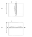
例えば、図3(A)に示すように、制御部12は、固体撮像素子10の中央部分のスリット状に結像された画像、すなわち画像30aを画像信号として読み出す。換言すると、制御部12は、固体撮像素子10の撮像面に撮像された画像から、スリット状の短手方向(x方向)の長さがW、長手方向(y方向)の長さがLである画像30aを読み出す。なお、画像30aにおける長さLは、長さyよりも小さくてもよい。
For example, as illustrated in FIG. 3A, the
また、制御部12は、図3(B)に示すように、固体撮像素子10の撮像面の長手方向に対して水平方向に撮像された画像から、スリット状の画像30bを画像信号として読み出すようにしてもよい。つまり、制御部12は、スリット状の短手方向(y方向)の長さがW、長手方向(x方向)の長さがLである画像30bを、固体撮像素子10の撮像面に撮像された画像から読み出す。すなわち、制御部12は、第2の画像を、この第2の画像の長手方向が、固体撮像素子10の撮像面の長手方向(x方向)と略平行となるように読み出すようにしてもよい。図3(B)に示す場合においては、画像30bとして読み出すことで、図3(A)の画像30aと比較して、より第2の画像の読み出し領域を大きくすることができる。したがって、撮像装置1においては、より広い範囲を撮影したパノラマ画像を合成することが可能となる。
Further, as shown in FIG. 3B, the
ここで、図3に示す画像30a又は画像30bの短手方向の幅が長すぎると、図2に示す投影面23が円柱と見なせなくなり、画像が滑らかに繋がらない可能性があり、記憶容量の大きなメモリ16が必要となる。また、画像30a又は画像30bの短手方向の長さWが短すぎても、合成する際の繋ぎ目部分が多くなりパノラマ画像が滑らかに繋がらなくなってしまったり、パノラマ画像の合成処理に時間がかかってしまう虞がある。
Here, if the width in the short direction of the
そこで、制御部12は、図3に示すように、固体撮像素子10から読み出す画像30a、画像30bの短手方向の長さWを固体撮像素子10のx方向又はy方向に対して10分の1程度とするのが好ましい。すなわち、制御部12は、図3(A)に示す例では、画像30aの短手方向の長さWを(x/10)とし、図3(B)に示す例では、画像30bの短手方向の長さWを(y/10)とするのが好ましい。例えば、撮像装置1において35mm換算で焦点距離が35mmの場合、短手方向の長さWに相当する水平画角は、約6度となる。
Therefore, as shown in FIG. 3, the
さらに、制御部12は、図3に示すように、固体撮像素子10の中央部の画角の狭い部分から画像30a又は画像30bを読み出すため、第2の画像における歪を小さくすることができる。例えば、制御部12は、第2の画像を固体撮像素子10の中央部以外から読み出す場合と比較して、読み出した第2の画像における歪をより小さくすることができる。したがって、撮像装置1においては、作成されるパノラマ画像の繋ぎ目を、より滑らかなものとすることができる。
Furthermore, as shown in FIG. 3, the
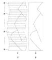
そして、制御部12は、複数の画像と、マイコン15により演算した画像に対応する撮影開始に対する相対的な角度とに基づいて、パノラマ画像を合成する。具体的には、制御部12は、図4(A)に示すように、メモリ16に記憶された複数の撮影開始位置に対する相対的な角度から、撮影開始時に撮像された第2の画像40と、その後に撮像された複数の第2の画像41、第2の画像42、・・・及び第2の画像66とのずれ量をそれぞれ算出する。そして、制御部12は、算出したずれ量に基づいて、第2の画像40から第2の画像66を重ね合わせることで合成画像70を作成する。そして、制御部12は、図4(B)に示すように、合成画像70に対してトリミング処理を施すことにより、合成画像70の長手方向の上下の凹凸部分を滑らかにしてパノラマ画像80を作成する。
And the
このように、撮像装置1においては、角速度センサ13により検出した角速度値に基づいて固体撮像素子10の撮像面に撮像された第1の画像の一部を構成するスリット状の短手方向の長さがWである第2の画像を読み出す。そして、撮像装置1においては、固体撮像素子10から読み出した複数の第2の画像と、この第2の画像にそれぞれ対応する撮影開始位置に対する相対的な角度とに基づいてパノラマ画像を合成する。
As described above, in the
したがって、撮像装置1では、従来のパノラマ画像作成方法においてパノラマ画像を合成する際に必要であった画像処理が不要となる。換言すると、撮像装置1においては、パノラマ画像を合成する際にトリミング以外の画像処理が不要となるため、パノラマ画像に劣化を生じさせず、高速に画像の繋ぎ目が滑らかなパノラマ画像を合成することが可能となる。
Therefore, the
また、撮像装置1においては、固体撮像素子10から読み出した複数の第2の画像と、これらの第2の画像に対応する撮影開始位置に対する相対的な角度をメモリ16に記憶させておく。そして、撮像装置1では、撮影終了後にメモリ16から相対的な角度を読み出して、撮影開始時に撮像された第2の画像とその後に撮像された第2の画像とのずれ量を算出する。このようにして、撮像装置1では、算出したずれ量に基づいてメモリ16から読み出した複数の第2の画像を重ね合わせてパノラマ画像を合成することで、より高速にパノラマ画像を合成することが可能となる。
In the
続いて、図5に示すフローチャートを参照しながら、本実施形態に係るパノラマ画像合成方法の処理例について説明する。なお、通常の撮影モードにおける処理動作については、省略するものとする。 Next, a processing example of the panoramic image synthesis method according to the present embodiment will be described with reference to the flowchart shown in FIG. Note that the processing operation in the normal shooting mode is omitted.
ステップS1では、撮像装置1においては、ハードウェアの診断や初期化を行った後、撮影パラメータ処理を行う。具体的に、制御部12は、露出計により識別された明るさに関する情報に基づいて絞り値やシャッタ速度を計算することで露出制御やホワイトバランスの調整を行う。また、制御部12は、EE(Electric To Electric)画像を表示部に表示させる。
In step S1, the
ステップS2では、制御部12は、例えば操作部18におけるシャッタボタンの押圧操作により生成される操作信号の有無に基づいて、撮影開始タイミングを識別する。制御部12は、シャッタボタンが押圧されたと判断した場合には、ステップS3の処理に移行する。一方、制御部12は、シャッタボタンが押圧されていないと判断した場合にはステップS1へ戻り、上述した撮影パラメータ処理を再び実行する。また、ステップS2では、制御部12は、ステップS1で調整した絞り値、シャッタ速度、ホワイトバランス等の撮影パラメータを固定する。また、マイコン15は、角速度センサ13から出力された角速度値の積分処理を開始し、この角速度値の積分処理を撮影終了まで続ける。
In step S <b> 2, the
ステップS3では、撮像装置1においては、画像の撮影を開始する。具体的に、制御部12は、角速度センサ13により検出した角速度値に基づいて、固体撮像素子10の撮像面から読み出すスリット状の短手方向の長さがWである第2の画像の読み出し幅を決定する。すなわち、制御部12は、角速度センサ13により検出した角速度値が所定の閾値以上である場合には、固体撮像素子10から第2の画像を読み出す際の長さWを大きくし、角速度値が所定の閾値未満である場合には、第2の画像を読み出す際の長さWを小さくする。例えば、制御部12は、図3(A)に示す固体撮像素子10の撮像面に撮像されたスリット状の画像30aのx方向の幅や、図3(B)に示す固体撮像素子10の撮像面に撮像されたスリット状の画像30bのy方向の幅を制御する。
In step S3, the
このように、制御部12は、角速度センサ13により検出した角速度値に応じて固体撮像素子10の撮像面から読み出す第2の画像の読み出し幅を決定することで、読み出した第2の画像を合成する際の繋ぎ目部分を調整することができる。したがって、撮像装置1においては、パノラマ画像を滑らかに繋げることができ、パノラマ画像の合成処理を高速に行うことが可能となる。また、撮像装置1においては、必要以上に記憶容量の大きなメモリ16が不要となるため、製造コストを削減することが可能となる。
As described above, the
また、制御部12は、角速度センサ13から出力される角速度値に応じて、連写速度を制御する。具体的に、制御部12は、角速度センサ13により検出した角速度値が所定の閾値以上である場合には固体撮像素子10における連写速度を上げ、角速度値が所定の閾値未満である場合には連写速度を下げる。すなわち、制御部12は、角速度センサ13から得られる角速度に応じて、連写時のシャッタのタイミングを制御する。このように、制御部12は、角速度値に応じて連写速度を制御することで、各画像が同じ角度となるように固体撮像素子10から読み出すことができる。このように撮像装置1においては、角速度センサ13からの角速度値に基づいて、第2の画像を読み出す際の長さWや連写速度を制御することで、合成されるパノラマ画像の繋ぎ目を滑らかにできるため、上述したように画像の劣化を防止することができる。
The
ステップS4では、制御部12は、例えば固体撮像素子10から読み出した第2の画像と、この第2の画像に対応するマイコン15により算出した撮影開始位置に対する現在の相対的な角度とをメモリ16に記憶する。
In step S4, the
ステップS5およびステップS6では、制御部12は、最後の撮影から一定時間内に撮像装置1が一定角度動いたか否かを判定する。制御部12は、撮像装置1が一定の角度動かないまま、最後の撮影から一定時間が経過した場合には、パノラマ画像の撮影が終了したものと判断し、ステップS7の処理に移行する。また、制御部12は、撮影終了のタイミングを、操作部18におけるシャッタボタンの押圧入力が継続しているか否かに基づいて判定するようにしてもよい。
In step S5 and step S6, the
ステップS5およびステップS6において、制御部12は、最後の撮影から一定時間内に撮像装置1が一定角度動いたと判断した場合には、ステップS3の処理を再度実行する。すなわち、制御部12は、一定時間内に撮像装置1が一定角度以上動くかどうかを判定し、一定角度以上動いた場合には、固体撮像素子10から第2の画像を読み出す。
In step S5 and step S6, when the
具体的に、パノラマ画像を合成するためには2割乃至5割程度のオーバーラップが必要となる。そこで、制御部12は、ステップS6の処理において、例えば35mm換算で焦点距離が35mmの場合、撮影開始位置に対して同一中心軸で4度ほど撮像装置1が回転すると、画像を撮影するステップS3の処理に移行するようにする。
Specifically, about 20% to 50% overlap is required to synthesize panoramic images. Therefore, in the process of step S6, for example, when the focal length is 35 mm in terms of 35 mm, the
ステップS7では、制御部12は、パノラマ画像を合成する。具体的に制御部12は、上述した図4(A)に示すように、メモリ16に記憶された複数の撮影開始位置に対する相対的な角度から、撮影開始時に撮像された第2の画像40と、その後に撮像された複数の第2の画像41、第2の画像42、・・・、及び第2の画像66とのずれ量をそれぞれ算出する。そして、制御部12は、算出した第2の画像40と、その他の第2の画像41乃至第2の画像66とのずれ量に基づいて、第2の画像40から第2の画像66を重ね合わせることで合成画像70を合成する。
In step S7, the
そして、制御部12は、図4(B)に示すように、合成画像70に対してトリミング処理を施すことにより、合成画像70の長手方向の上下の凹凸部分を滑らかにしてパノラマ画像80を作成する。
Then, as shown in FIG. 4B, the
このように、撮像装置1では、従来のパノラマ画像の作成において画像の繋ぎ目を滑らかにするために必要だった画像処理が不要となるため、パノラマ画像を高速で作成することができる。
As described above, the
ステップS8では、制御部12は、パノラマ画像をメモリ16に記録する。具体的に、制御部12は、ステップS7で合成したパノラマ画像80に対して所定の画像処理、圧縮処理を行い、記録媒体17に記憶する。
In step S <b> 8, the
以上のように、撮像装置1によれば、角速度センサ13から出力される角速度値に応じて、固体撮像素子10から第2の画像を読み出す際の長さWを制御する。撮像装置1では、読み出した第2の画像と、第2の画像に対応するマイコン15により演算した撮影開始位置に対する相対的な角度とをメモリ16に記憶する。撮像装置1では、メモリ16に記憶された複数の撮影開始位置に対する相対的な角度から撮影開始時に撮像された第2の画像とその後に撮像された複数の第2の画像とのずれ量をそれぞれ算出する。そして、撮像装置1では、算出したずれ量に基づいて複数の第2の画像を重ね合わせることでパノラマ画像を合成する。
As described above, according to the
ここで、従来のパノラマ画像の作成方法では、撮像装置の指示に従って、複数枚の画像を撮影し、撮影終了後にPC等でパノラマ画像を合成する必要があるため、撮影終了後すぐにパノラマ画像を鑑賞することができない。また、従来のパノラマ画像の作成方法では、撮像装置内でパノラマ画像を作成することができる場合でも、撮像装置の指示に従って複数枚の画像を撮影してパノラマ画像を合成するため、パノラマ画像の作成に時間を要することになる。さらに、従来のパノラマ画像の作成方法では、多角形状に撮影された画像同士を繋ぎ合わせる際に、画像の繋ぎ目を滑らかにするための画像処理が必要になるため、画像処理に伴う画像の劣化が生じてしまう。 Here, in the conventional panoramic image creation method, it is necessary to shoot a plurality of images in accordance with an instruction from the imaging device and synthesize the panoramic image with a PC or the like after the shooting is completed. I can't appreciate it. In addition, in the conventional panorama image creation method, even when a panorama image can be created in the imaging device, a plurality of images are shot and combined to create a panorama image according to the instructions of the imaging device. It will take time. Furthermore, the conventional panoramic image creation method requires image processing to smooth the joints of images when connecting images captured in a polygonal shape. Will occur.
一方、撮像装置1によれば、パノラマ画像を合成する際に画像の繋ぎ目を滑らかにするための画像処理が不要となる、換言すると、トリミング以外の処理が不要となる。したがって、撮像装置1によれば、パノラマ画像に劣化を生じさせず、画像の繋ぎ目が滑らかなパノラマ画像を高速で作成することが可能となる。また、撮像装置1によれば、撮影直後に合成したパノラマ画像をLCDパネル等の表示部で鑑賞することが可能となる。また、撮像装置1によれば、角速度に応じた長さWの第2の画像を固体撮像素子10から読み出すことで、従来のパノラマ撮影方法のように、撮影指示に従うことなく撮影を行うことができるため、撮影の際の煩わしさを解消することができる。
On the other hand, according to the
なお、上述した実施の形態では、撮影方向を水平方向へ移動させる場合を例に挙げて説明したが、かかる場合に限定されるものではなく、例えば撮影方向を垂直方向へ移動させる場合においても本発明を同様に適用することが可能である。また、図3に示す処理手順ように、撮影終了後にパノラマ画像を合成する例に限定されず、例えば、制御部12は、順次リアルタイムでパノラマ画像を合成するような処理を行うようにしてもよい。また、角速度センサ13の代わりに、例えば加速度センサを用いて、撮像装置1における加速度を検出し、マイコン15により撮影開始位置に対する相対的な角度を演算するようにしてもよい。また、制御部12は、上述した処理動作のプログラムを、ハードウェア又はソフトウェア或いは両者の複合構成によって実行することが可能である。
In the above-described embodiment, the case where the shooting direction is moved in the horizontal direction has been described as an example. However, the present invention is not limited to such a case. For example, the case where the shooting direction is moved in the vertical direction is also described. It is possible to apply the invention as well. Further, as illustrated in the processing procedure illustrated in FIG. 3, the present invention is not limited to the example in which the panoramic image is synthesized after the photographing is completed. . Further, instead of the
1 撮像装置、10 固体撮像素子、11 AFE、12 制御部、13 角速度センサ、14 スイッチ、15 マイコン、16 メモリ、17 記録媒体
DESCRIPTION OF
Claims (7)
当該撮像装置の動きに基づいて、撮影開始位置に対する相対的な角度を検出する角度検出部と、
上記撮像部の撮像面に撮像された第1の画像の一部を構成するスリット状の短手方向の長さWの第2の画像を上記撮像面の中央部分から読み出し、当該読み出した複数の第2の画像と、当該複数の第2の画像それぞれに対応する上記撮影開始位置に対する相対的な角度とに基づいて、パノラマ画像を合成する制御部とを備え、
上記制御部は、当該撮像装置の動きに基づいて、上記第2の画像を読み出す際の上記長さW又は上記撮像部の連写速度を制御する撮像装置。 An imaging unit that captures an image of a subject incident from a lens on an imaging surface;
An angle detector that detects a relative angle with respect to the shooting start position based on the movement of the imaging device;
A second image having a slit-like length W in the lateral direction that constitutes a part of the first image captured on the imaging surface of the imaging unit is read from the central portion of the imaging surface, and the plurality of read-out plural images A control unit that synthesizes a panoramic image based on a second image and a relative angle with respect to the shooting start position corresponding to each of the plurality of second images;
The said control part is an imaging device which controls the said length W at the time of reading a said 2nd image, or the continuous shooting speed of the said imaging part based on the motion of the said imaging device.
上記撮影開始から撮影終了までの角速度値を検出する角速度センサと、
上記角速度センサにより検出した上記角速度値を積分して、上記撮影開始位置に対する相対的な角度を演算する演算部と
を備え、
上記制御部は、上記角速度センサにより検出した角速度値に基づいて、上記第2の画像を読み出す際の上記長さW又は上記撮像部の連写速度を制御する請求項1記載の撮像装置。 The angle detector is
An angular velocity sensor that detects an angular velocity value from the start of shooting to the end of shooting;
A calculation unit that integrates the angular velocity value detected by the angular velocity sensor and calculates a relative angle with respect to the photographing start position;
The imaging apparatus according to claim 1, wherein the control unit controls the length W or the continuous shooting speed of the imaging unit when reading the second image based on an angular velocity value detected by the angular velocity sensor.
上記制御部は、撮影終了後に上記記憶部に記憶された複数の上記撮影開始位置に対する相対的な角度から、撮影開始時に撮像された上記第2の画像と、その後に撮像された上記複数の第2の画像とのずれ量をそれぞれ算出し、当該ずれ量に基づいて上記複数の第2の画像を重ね合わせることで、上記パノラマ画像を合成する請求項2記載の撮像装置。 A storage unit for storing a relative angle with respect to the shooting start position calculated by the calculation unit corresponding to the plurality of second images read by the control unit and the plurality of second images;
The control unit, based on a relative angle with respect to the plurality of shooting start positions stored in the storage unit after completion of shooting, the second image captured at the start of shooting, and the plurality of second images captured thereafter. The imaging apparatus according to claim 2, wherein the amount of deviation from the second image is calculated, and the panoramic image is synthesized by superimposing the plurality of second images based on the amount of deviation.
撮像装置の動きに基づいて、撮影開始に対する相対的な角度を角度検出部により検出する角度検出工程と、
上記撮像面に撮像された第1の画像の一部を構成するスリット状の短手方向の長さWの第2の画像を上記撮像面の中央部分から読み出す読み出し工程と、
複数の上記第2の画像と当該複数の第2の画像それぞれに対応する上記撮影開始位置に対する相対的な角度とに基づいて、パノラマ画像を合成する合成工程とを有し、
上記読み出し工程では、上記撮像装置の動きに基づいて、上記第2の画像を読み出す際の上記長さW又は上記撮像部の連写速度を制御する画像処理方法。 An imaging step of imaging a subject image incident from a lens on an imaging surface;
An angle detection step of detecting, by an angle detection unit, a relative angle with respect to the start of shooting based on the movement of the imaging device;
A reading step of reading out a second image having a length W in the short-side direction, which forms a part of the first image captured on the imaging surface, from the central portion of the imaging surface ;
Combining a panoramic image based on a plurality of the second images and a relative angle with respect to the shooting start position corresponding to each of the plurality of second images,
In the reading step, an image processing method for controlling the length W or the continuous shooting speed of the imaging unit when reading the second image based on the movement of the imaging device.
撮像装置の動きに基づいて、撮影開始に対する相対的な角度を角度検出部により検出する角度検出工程と、
上記撮像面に撮像された第1の画像の一部を構成するスリット状の短手方向の長さWの第2の画像を上記撮像面の中央部分から読み出す読み出し工程と、
複数の上記第2の画像と当該複数の第2の画像それぞれに対応する上記撮影開始位置に対する相対的な角度とに基づいて、パノラマ画像を合成する合成工程とを有し、
上記読み出し工程では、上記撮像装置の動きに基づいて、上記第2の画像を読み出す際の上記長さW又は上記撮像部の連写速度を制御する処理をコンピュータに実行させるためのプログラム。 An imaging step of imaging a subject image incident from a lens on an imaging surface;
An angle detection step of detecting, by an angle detection unit, a relative angle with respect to the start of shooting based on the movement of the imaging device;
A reading step of reading out a second image having a length W in the short-side direction, which forms a part of the first image captured on the imaging surface, from the central portion of the imaging surface ;
Combining a panoramic image based on a plurality of the second images and a relative angle with respect to the shooting start position corresponding to each of the plurality of second images,
In the reading step, a program for causing a computer to execute processing for controlling the length W or the continuous shooting speed of the imaging unit when reading the second image based on the movement of the imaging device.
Priority Applications (1)
| Application Number | Priority Date | Filing Date | Title |
|---|---|---|---|
| JP2008191230A JP5115731B2 (en) | 2008-07-24 | 2008-07-24 | Imaging apparatus, image processing method, and program |
Applications Claiming Priority (1)
| Application Number | Priority Date | Filing Date | Title |
|---|---|---|---|
| JP2008191230A JP5115731B2 (en) | 2008-07-24 | 2008-07-24 | Imaging apparatus, image processing method, and program |
Publications (2)
| Publication Number | Publication Date |
|---|---|
| JP2010028764A JP2010028764A (en) | 2010-02-04 |
| JP5115731B2 true JP5115731B2 (en) | 2013-01-09 |
Family
ID=41734112
Family Applications (1)
| Application Number | Title | Priority Date | Filing Date |
|---|---|---|---|
| JP2008191230A Active JP5115731B2 (en) | 2008-07-24 | 2008-07-24 | Imaging apparatus, image processing method, and program |
Country Status (1)
| Country | Link |
|---|---|
| JP (1) | JP5115731B2 (en) |
Cited By (1)
| Publication number | Priority date | Publication date | Assignee | Title |
|---|---|---|---|---|
| US10445909B2 (en) | 2015-11-30 | 2019-10-15 | Canon Kabushiki Kaisha | Image processing apparatus that generates a wide angle image using a plurality of images, and related control method and storage medium |
Families Citing this family (7)
| Publication number | Priority date | Publication date | Assignee | Title |
|---|---|---|---|---|
| KR101756839B1 (en) * | 2011-05-17 | 2017-07-11 | 삼성전자주식회사 | Digital photographing apparatus and control method thereof |
| JP5996169B2 (en) | 2011-07-27 | 2016-09-21 | オリンパス株式会社 | Image processing system, information processing apparatus, and program |
| JP6124700B2 (en) | 2012-07-27 | 2017-05-10 | キヤノン株式会社 | IMAGING DEVICE, ITS CONTROL METHOD, PROGRAM, AND STORAGE MEDIUM |
| JP2019021968A (en) | 2017-07-11 | 2019-02-07 | キヤノン株式会社 | Image coding apparatus and control method thereof |
| JP7163057B2 (en) | 2018-04-26 | 2022-10-31 | キヤノン株式会社 | IMAGING DEVICE, IMAGING METHOD, PROGRAM AND RECORDING MEDIUM |
| JP7051570B2 (en) | 2018-05-09 | 2022-04-11 | キヤノン株式会社 | Image control device, control method and program of image control device |
| JP7086774B2 (en) | 2018-07-25 | 2022-06-20 | キヤノン株式会社 | Imaging equipment, imaging methods and programs |
Family Cites Families (3)
| Publication number | Priority date | Publication date | Assignee | Title |
|---|---|---|---|---|
| JP3066992B2 (en) * | 1991-12-06 | 2000-07-17 | 日本電信電話株式会社 | Image shooting processing method |
| JPH11341328A (en) * | 1998-05-26 | 1999-12-10 | Sony Corp | Image data display apparatus and method, and providing medium |
| JP2000032379A (en) * | 1998-07-08 | 2000-01-28 | Olympus Optical Co Ltd | Electronic camera |
-
2008
- 2008-07-24 JP JP2008191230A patent/JP5115731B2/en active Active
Cited By (1)
| Publication number | Priority date | Publication date | Assignee | Title |
|---|---|---|---|---|
| US10445909B2 (en) | 2015-11-30 | 2019-10-15 | Canon Kabushiki Kaisha | Image processing apparatus that generates a wide angle image using a plurality of images, and related control method and storage medium |
Also Published As
| Publication number | Publication date |
|---|---|
| JP2010028764A (en) | 2010-02-04 |
Similar Documents
| Publication | Publication Date | Title |
|---|---|---|
| JP5413344B2 (en) | Imaging apparatus, image composition method, and program | |
| JP4900401B2 (en) | Imaging apparatus and program | |
| JP5163676B2 (en) | Imaging apparatus, imaging method, and program | |
| JP4293053B2 (en) | Imaging apparatus and method | |
| JP2010028764A (en) | Imaging apparatus, image processing method, and program | |
| KR101346426B1 (en) | Image processing device capable of generating wide-range image | |
| CN101931752A (en) | Camera device, and focusing method | |
| JP5644882B2 (en) | Imaging apparatus, field angle correction method, and program | |
| JP5696419B2 (en) | Image processing apparatus and method, and program | |
| JP4957825B2 (en) | Imaging apparatus and program | |
| JP2009278432A (en) | Imaging apparatus, and imaging method in imaging apparatus | |
| JP2009055160A (en) | Imaging apparatus and imaging method | |
| JP4986189B2 (en) | Imaging apparatus and program | |
| JP2004328606A (en) | Imaging device | |
| JP2000224462A (en) | Camera system | |
| JP5021370B2 (en) | Imaging apparatus, display method, and program | |
| JP2007336394A (en) | Imaging apparatus and image composition method | |
| JP6717354B2 (en) | Image processing apparatus, image processing method and program | |
| JP2012124575A (en) | Imaging apparatus | |
| JP5831492B2 (en) | Imaging apparatus, display control method, and program | |
| JP2001223942A (en) | Imaging apparatus, control method of imaging apparatus, imaging method of panorama composition image, medium for supplying control program of imaging apparatus | |
| JP5166966B2 (en) | Camera device, composite image creation support device, composite image creation support method, and composite image creation support program | |
| JP7860710B2 (en) | Imaging device, its control method, and program | |
| JP5613145B2 (en) | Imaging apparatus and program | |
| JP5845763B2 (en) | Imaging apparatus, image processing method, and program |
Legal Events
| Date | Code | Title | Description |
|---|---|---|---|
| A621 | Written request for application examination |
Free format text: JAPANESE INTERMEDIATE CODE: A621 Effective date: 20110428 |
|
| A977 | Report on retrieval |
Free format text: JAPANESE INTERMEDIATE CODE: A971007 Effective date: 20120426 |
|
| A131 | Notification of reasons for refusal |
Free format text: JAPANESE INTERMEDIATE CODE: A131 Effective date: 20120508 |
|
| A521 | Request for written amendment filed |
Free format text: JAPANESE INTERMEDIATE CODE: A523 Effective date: 20120703 |
|
| TRDD | Decision of grant or rejection written | ||
| A01 | Written decision to grant a patent or to grant a registration (utility model) |
Free format text: JAPANESE INTERMEDIATE CODE: A01 Effective date: 20120919 |
|
| A01 | Written decision to grant a patent or to grant a registration (utility model) |
Free format text: JAPANESE INTERMEDIATE CODE: A01 |
|
| A61 | First payment of annual fees (during grant procedure) |
Free format text: JAPANESE INTERMEDIATE CODE: A61 Effective date: 20121002 |
|
| R151 | Written notification of patent or utility model registration |
Ref document number: 5115731 Country of ref document: JP Free format text: JAPANESE INTERMEDIATE CODE: R151 |
|
| FPAY | Renewal fee payment (event date is renewal date of database) |
Free format text: PAYMENT UNTIL: 20151026 Year of fee payment: 3 |
|
| R250 | Receipt of annual fees |
Free format text: JAPANESE INTERMEDIATE CODE: R250 |
|
| R250 | Receipt of annual fees |
Free format text: JAPANESE INTERMEDIATE CODE: R250 |
|
| R250 | Receipt of annual fees |
Free format text: JAPANESE INTERMEDIATE CODE: R250 |
|
| R250 | Receipt of annual fees |
Free format text: JAPANESE INTERMEDIATE CODE: R250 |
|
| R250 | Receipt of annual fees |
Free format text: JAPANESE INTERMEDIATE CODE: R250 |
|
| R250 | Receipt of annual fees |
Free format text: JAPANESE INTERMEDIATE CODE: R250 |