JP5115942B2 - Piping for fuel cell and manufacturing method thereof - Google Patents
Piping for fuel cell and manufacturing method thereof Download PDFInfo
- Publication number
- JP5115942B2 JP5115942B2 JP2001250156A JP2001250156A JP5115942B2 JP 5115942 B2 JP5115942 B2 JP 5115942B2 JP 2001250156 A JP2001250156 A JP 2001250156A JP 2001250156 A JP2001250156 A JP 2001250156A JP 5115942 B2 JP5115942 B2 JP 5115942B2
- Authority
- JP
- Japan
- Prior art keywords
- pipe
- fuel cell
- manufacturing
- stainless steel
- piping
- Prior art date
- Legal status (The legal status is an assumption and is not a legal conclusion. Google has not performed a legal analysis and makes no representation as to the accuracy of the status listed.)
- Expired - Fee Related
Links
Images





Classifications
-
- Y—GENERAL TAGGING OF NEW TECHNOLOGICAL DEVELOPMENTS; GENERAL TAGGING OF CROSS-SECTIONAL TECHNOLOGIES SPANNING OVER SEVERAL SECTIONS OF THE IPC; TECHNICAL SUBJECTS COVERED BY FORMER USPC CROSS-REFERENCE ART COLLECTIONS [XRACs] AND DIGESTS
- Y02—TECHNOLOGIES OR APPLICATIONS FOR MITIGATION OR ADAPTATION AGAINST CLIMATE CHANGE
- Y02E—REDUCTION OF GREENHOUSE GAS [GHG] EMISSIONS, RELATED TO ENERGY GENERATION, TRANSMISSION OR DISTRIBUTION
- Y02E60/00—Enabling technologies; Technologies with a potential or indirect contribution to GHG emissions mitigation
- Y02E60/30—Hydrogen technology
- Y02E60/50—Fuel cells
-
- Y—GENERAL TAGGING OF NEW TECHNOLOGICAL DEVELOPMENTS; GENERAL TAGGING OF CROSS-SECTIONAL TECHNOLOGIES SPANNING OVER SEVERAL SECTIONS OF THE IPC; TECHNICAL SUBJECTS COVERED BY FORMER USPC CROSS-REFERENCE ART COLLECTIONS [XRACs] AND DIGESTS
- Y02—TECHNOLOGIES OR APPLICATIONS FOR MITIGATION OR ADAPTATION AGAINST CLIMATE CHANGE
- Y02P—CLIMATE CHANGE MITIGATION TECHNOLOGIES IN THE PRODUCTION OR PROCESSING OF GOODS
- Y02P70/00—Climate change mitigation technologies in the production process for final industrial or consumer products
- Y02P70/50—Manufacturing or production processes characterised by the final manufactured product
Landscapes
- Fuel Cell (AREA)
- Cleaning In General (AREA)
- Rigid Pipes And Flexible Pipes (AREA)
- Chemically Coating (AREA)
Description
【0001】
【発明の属する技術分野】
本発明は、燃料電池、特に固体高分子型燃料電池のシステムに用いられる配管とその製造方法に関する。
【0002】
【従来の技術】
地球温暖化、有害物質による大気汚染または化石燃料の埋蔵量の減少に伴うエネルギー問題の対策の一環として燃料電池の開発が進められている。特に燃料電池自動車については、厳しい走行条件への適合のみならず経済性、効率性等の改善が求められている。
自動車搭載用として最有力視されている固体高分子型燃料電池は、水素と酸素を反応させ、その際に生成する電気エネルギーを取出すもので、水素イオンを選択的に透過するイオン交換膜を電極で挟み込み、負極側に水素、正極側に酸素をそれぞれ流す構造となっている。このイオン交換膜は、一般的に50〜200μm程度の非常に薄い膜で形成されているため、配管システム内の異物により破壊され易いばかりでなく、電極における触媒反応を阻害する鉄、銅やアルミニウム等のイオンが配管内に残留していたり、新たに発生することにより性能を低下させるため、配管内は異物の残留が極めて少なく、触媒反応を損なうイオンが残留しない清浄な状態が求められている。
【0003】
この燃料電池用配管には、SUS304やSUS316等のオーステナイト系ステンレス鋼が用いられ、内面を清浄化するため酸洗や電解研磨等を施し、超純水で十分洗浄された高価な配管材料が使用されている。また、フレアー等の配管接続部および曲げ加工部等の塑性加工を受ける部位は、残留応力による応力腐食を避けるため、接続用の管端末部を成形したり曲げ加工を施さずに、内面を清浄化した高価な継手部品等を多数組合わせて用い接続して配管を構成している。さらに、これらの配管材料は、溶接時の熱影響によって鋭敏化した部分の腐食が進むのを避けるため、一切の熱が付加されないよう配慮されている。このような燃料電池用配管は、一般にステンレス配管専用(鉄などの他の材料の製品は一切加工しない)設備で切断、端末成形、穿孔、曲げ等の加工が施され、清浄化処理された後、予め清浄化処理された継手部品等を組付けて配管システムを製造している。
【0004】
【発明が解決しようとする課題】
しかしながら、ステンレス配管専用設備で燃料電池用配管を製造する従来の方法では、配管設計や製造に制約を受けるばかりか、配管システム価格が非常に高価なものとなるという問題があった。
本発明は、このような従来の問題を解決するためになされたもので、内面が清浄でかつ触媒反応に支障を及ぼすような有害イオンの残留や発生がなく、さらには応力腐食を生じさせるような鋭敏化した組織のない品質良好な燃料電池用配管と、この品質良好な燃料電池用配管をステンレス配管専用設備以外の通常の鋼管等の配管製造設備により安価に提供することができる燃料電池用配管の製造方法を提案することを目的とするものである。
【0005】
【課題を解決するための手段】
本発明に係る燃料電池用配管は、切断工程、成形工程、穿孔工程、仮付け工程、ろう付・固溶体化熱処理工程のいずれか必要な工程と内面清浄化処理工程とからなる製造ラインにより製造されるステンレス鋼製の燃料電池用配管であって、前記内面清浄化処理工程で端面を含む少なくとも管内面に付着する金属粉を溶解除去する清浄化処理を施した後に、化学Niめっき工程で端面を含む少なくとも管内面に化学Niめっきを施すことによって、端面を含む少なくとも管内面に金属イオンの生成を防止することを特徴とするものである。
また、上記燃料電池用配管の製造方法は、切断工程、成形工程、穿孔工程、仮付け工程、ろう付・固溶体化熱処理工程のいずれか必要な工程と内面清浄化処理工程とからなる製造ラインによりステンレス鋼製の燃料電池用配管を製造する方法において、前記内面清浄化処理工程で端面を含む少なくとも管内面に付着する金属粉を溶解除去する清浄化処理を施した後、化学Niめっき工程で端面を含む少なくとも管内面に化学Niめっきを施すことを特徴とするものである。
本発明において、前記成形工程にて端末成形および曲げ加工を施した後、付属部品を管に取付ける場合は、仮付け溶接後、固溶体化熱処理工程にてろう付けを行うことを好ましい態様とし、さらに、前記ろう付け手段としては、水素雰囲気中または真空中にてニッケルろう付けする方法を用いることを好ましい態様とするものである。
なお、ここでいう固溶体化熱処理とは、JIS B 6905「金属製品熱処理用語」の番号1611記載の「溶体化処理」を完璧に実施することをいうのではなく、Niろう付け時の1000℃を超える加熱により仮付け溶接の加熱で生じた結晶粒界付近の炭化クロムをオーステナイト結晶粒内の固溶を促進させ、完全なる急冷はできなくても、溶体化処理された組織に類似させて鋭敏化していない組織を得る熱処理のことをいう。
また、Niろう付けとしては、例えば特開2000−219389、特開2000−218390等に記載されている方法を用いることができる。
【0006】
本発明において、内面清浄化処理工程で端面を含む少なくとも管内面に付着する金属粉を溶解除去する清浄化処理を施すこととしたのは、以下に記載する理由による。
ステンレス配管専用設備以外の通常の鋼管等の配管製造設備によりステンレス鋼製の燃料電池用配管を製造する場合、切断加工や曲げ加工時に既設の設備に付着しているステンレス鋼以外の金属粉が当該ステンレス配管に付着し、これが腐食・溶出することにより燃料電池の触媒反応に有害な鉄イオン等が発生する。一方、溶接やろう付け工程で発生する熱により、ステンレス管の一部が鋭敏化することにより、当該部分が配管の流体である水分により腐食する。これにより燃料電池用配管としての機能を損なうばかりか、腐食による鉄イオンの流出により触媒反応が損なわれる。
本発明は、このような問題を解決し、内面が清浄でかつ触媒反応に支障を及ぼすような有害イオンの残留や発生がなく、さらには応力腐食を生じさせるような鋭敏化した組織のない品質良好なステンレス鋼製の燃料電池用配管をステンレス配管専用設備以外の通常の配管製造設備により製造する手段として、前記内面清浄化処理工程で端面を含む少なくとも管内面に付着する金属粉を溶解除去する清浄化処理を施す方法を採用したものである。ここで、管内面に付着する金属粉を溶解除去する方法としては、特に限定するものではないが、脱脂後、酸洗浄する方法を用いることができる。
【0007】
また、本発明において、上記清浄化処理を施した後、化学Niめっき工程で端面を含む少なくとも管内面に化学Niめっきを施すのは、例え清浄化処理において、鉄粒子等が内周面に残留するようなことがあっても、化学Niメッキ被膜により被覆されて遮蔽されることとなり、鉄イオン等が溶出して触媒反応に悪影響を及ぼすことが確実に防止できるからである
【0008】
【発明の実施の形態】
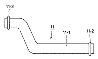
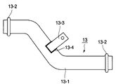
図1〜図4は本発明に係るステンレス鋼製の燃料電池用配管を例示したもので、図1は管端部にスプールが設けられた燃料電池用配管の一例を示す側面図、図2は管端にフランジが取付けられた燃料電池用配管の一例を示す側面図、図3は管本体の外面にブラケットが取付けられた燃料電池用配管の一例を示す側面図、図4は管本体にニップルが取付けられた燃料電池用配管の一例を示す一部破断側面図、図5は管端にフランジをろう付けした他の燃料電池用配管の一例を示す部分拡大図、図6は本発明に係る燃料電池用配管の製造方法の一実施例を示す製造工程図、図7は同じく他の実施例を示す製造工程図、図8は図1に示す燃料電池用配管の製造工程図、図9は図2に示す燃料電池用配管の製造工程図、図10は図3に示す燃料電池用配管の製造工程図、図11は図4に示す燃料電池用配管の製造工程図である。
【0009】
図1に示すステンレス鋼製の燃料電池用配管11は、両管端部に膨出加工によりスプール11−2を形成した管体11−1に曲げ加工が施されたものである。図2に示すステンレス鋼製の燃料電池用配管12は、曲げ加工が施された管体12−1の両管端に、締結用フランジ12−2を外嵌し、その嵌合部の外周縁部を仮付け溶接後Niろう付けしたもので、12−3がそのNiろう付け部である。図3に示すステンレス鋼製の燃料電池用配管13は、膨出加工によりスプール13−2が形成された管体13−1に曲げ加工が施され、この曲げ加工が施された管体13−1の曲管部の外周面に固定用ブラケット13−3を仮付け溶接後Niろう付けしたもので、13−4がそのNiろう付け部である。図4に示すステンレス鋼製の燃料電池用配管14は、曲げ加工が施された管体14−1の曲管部に分岐孔14−1aを穿設し、該管体14−1の両管端に締結用フランジ14−2を、前記分岐孔14−1aにニップル14−3をそれぞれ仮付け溶接し、しかる後締結用フランジ14−2とニップル14−3を同時にNiろう付けしたもので、14−4、14−5がNiろう付け部である。
【0010】
図5に示すステンレス鋼製の燃料電池用配管15は、管体15−1の管端部に当該管端部の開口端面を覆うように形成した締結用フランジ15−2を外嵌し、その嵌合部の外周縁部をNiろう付けしたもので、15−3がそのNiろう付け部である。この燃料電池用配管15の場合は、フランジ15−2と管体15−1の間にできる隙間にNiろう材15−4が充填されることにより、管体15−1の内表面にはろう材フィレットが形成され隙間がなくなり、隙間腐食が防止される。
【0011】
上記した図1〜図5に示すステンレス鋼製の燃料電池用配管11〜15は、すべて内面清浄化処理工程で金属粉が溶解除去されている。したがって、触媒反応に支障を及ぼすような有害イオンの残留や発生がない。
【0012】
次に、図6、図7に示すステンレス鋼製の燃料電池用配管の製造方法について説明する。
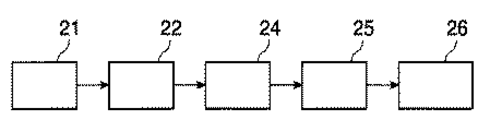
まず図6に示すステンレス鋼製の燃料電池用配管の製造方法は、通常の配管製造設備にてステンレス鋼製の燃料電池用配管を製造する方法であり、管体を所定の長さに切断する切断工程21、所定の長さに切断された管体に端末成形や曲げ加工を施す成形工程22、分岐孔等の孔をあける穿孔工程23、管端部や分岐孔等にフランジや分岐管等の部品を仮付けする仮付け工程24、前記部品をろう付けするろう付・固溶体化熱処理工程25と、端面を含む少なくとも管内面に付着する金属粉を溶解除去する内面清浄化処理工程26からなる製造ラインにてステンレス鋼製の燃料電池用配管を製造する方法である。
この方法において、端面を含む少なくとも管内面に付着する金属粉を溶解除去する清浄化処理手段としては、脱脂後、酸洗浄する方法を用いることができる。この場合、脱脂は塩化メチレンに常温で数分間浸漬して行い、酸洗浄は例えば15v/v%HNO3水溶液(67w/w%HNO3使用)+5v/v%HF水溶液(46w/w%HF使用)を用いて、60℃で10分程度浸漬して行う方法を用いることができる。
【0013】
図7にステンレス鋼製の燃料電池用配管の製造方法は、前記図6に示す製造方法に端面を含む少なくとも管内面に化学Niめっきを施す化学Niめっき工程27を加えた製造ラインにてステンレス鋼製の燃料電池用配管を製造する方法であり、化学Niめっき工程27以外は前記図6に示す製造方法と同様の工程からなる。
すなわち、管体を所定の長さに切断する切断工程21、所定の長さに切断された管体に端末成形や曲げ加工を施す成形工程22、分岐孔等の孔をあける穿孔工程23、管端部や分岐孔等にフランジや分岐管等の部品を仮付けする仮付け工程24、前記部品をろう付けするろう付・固溶体化熱処理工程25、端面を含む少なくとも管内面に付着する金属粉を溶解除去する内面清浄化処理工程26と、前記金属粉を溶解除去された管体の内外面にニッケルめっきを施す化学Niめっき工程27からなる製造ラインにてステンレス鋼製の燃料電池用配管を製造する方法である。化学Niめっき方法としては、無電解ニッケルめっきを用いることができる。
【0014】
図8に示す燃料電池用配管の製造方法は、切断工程21で管体を所定の長さに切断し、成形工程22で管体11−1の両管端部に膨出加工によりスプール11−2を形成すると共に、曲げ加工を施し、しかる後内面清浄化処理工程26で端面を含む少なくとも管内面に付着する金属粉を溶解除去する方法である。
図9に示す燃料電池用配管の製造方法は、切断工程21で管体を所定の長さに切断し、成形工程22で曲げ加工を施すと共に、その曲げ加工が施された管体12−1の両管端に仮付け工程24で締結用フランジ12−2を外嵌しその嵌合部の外周縁部を仮付け溶接した後、ろう付・固溶体化熱処理工程25でNiろう付けし、しかる後内面清浄化処理工程26で端面を含む少なくとも管内面に付着する金属粉を溶解除去する方法である。
図10に示す燃料電池用配管の製造方法は、切断工程21で管体を所定の長さに切断し、成形工程22で管体13−1の両管端部に膨出加工によりスプール13−2を形成すると共に、曲げ加工を施し、次いで仮付け工程24で管体13−1の曲管部の外周面に締結用ブラケット13−3を仮付け溶接した後、ろう付・固溶体化熱処理工程25でNiろう付けし、しかる後内面清浄化処理工程26で端面を含む少なくとも管内面に付着する金属粉を溶解除去する方法である。
図11に示す燃料電池用配管の製造方法は、切断工程21で管体を所定の長さに切断し、成形工程22で曲げ加工を施し、続いて穿孔工程23で曲げ加工が施された管体14−1の曲管部に分岐孔14−1aを穿設し、次いで仮付け工程24で管体14−1の両管端に締結用フランジ14−2を外嵌しその嵌合部の外周縁部を仮付け溶接した後、ろう付・固溶体化熱処理工程25でNiろう付けし、しかる後内面清浄化処理工程26で端面を含む少なくとも管内面に付着する金属粉を溶解除去する方法である。
【0015】
【実施例】
実施例1
外径38mmφ×厚さ1.2mmのステンレス鋼管(SUS304材)を用い、ステンレス配管専用設備を除く既存の鋼管製造設備により燃料電池用配管を製造した。本実施例では、所定の長さに切断したステンレス鋼管に対し、成形工程にて片端に端末バルジ加工を施し、続いてスチール製芯金を使用して当該鋼管に曲げ加工を施し、次いで孔あけ加工(孔径5.5mmφ)を施し、しかる後前記孔部にステンレス鋼管製分岐管(外径6.35mmφ、肉厚0.5mm、長さ25mm)を仮付け溶接し、さらに管端部にステンレス製締結用フランジ(外径115mmφ、厚さ12mm)を仮付け溶接した後、水素炉で通常のニッケルろう付けと固溶体化熱処理を施し、最終工程の内面清浄化処理工程にて脱脂後、酸洗浄を行って端面を含む管内面に付着する金属粉を溶解除去した。脱脂は塩化メチレンに常温で3分間浸漬して行い、酸洗浄は15v/v%HNO3水溶液(67w/w%HNO3使用)+5v/v%HF水溶液(46w/w%HF使用)を用いて、60℃で10分浸漬した。
そして洗浄後のステンレス鋼製燃料電池用配管を軸方向に半割切断し、一方は内面、他方は外面を対象に塩水噴霧試験を168時間実施し、錆の発生状況を観察した結果、端末成形部、曲げ加工部、分岐管ろう付け部、フランジろう付け部およびろう付けのための仮付け溶接部周辺すべてにわたり赤錆(鉄錆)の発生は確認されなかった。
【0016】
実施例2
外径16mmφ×厚さ1.2mmのステンレス鋼管(SUS316材)を用い、ステンレス配管専用設備を除く既存の鋼管製造設備により実施例1と同様の条件(フランジは外径80mmφ、厚さ9mm)で燃料電池用配管を製造し、得られた燃料電池用配管を実施例1と同様の評価試験を行って錆の発生状況を観察した結果、本実施例においても端末成形部、曲げ加工部、分岐管ろう付け部、フランジろう付け部およびろう付けのための仮付け溶接部周辺すべてにわたり赤錆(鉄錆)の発生は確認されなかった。
【0017】
実施例3
外径38mmφ×厚さ1.2mmのステンレス鋼管(SUS304材)を用い、ステンレス配管専用設備を除く既存の鋼管製造設備により実施例1と同様の条件で孔あけ加工、端末バルジ加工、曲げ加工、分岐管およびフランジの仮付け溶接、ニッケルろう付けと固溶体化熱処理を施した後、アルカリ脱脂、水洗、酸洗を行って端面を含む管内面に付着する金属粉を溶解除去し、その後水洗し、分岐管およびフランジを含む内外面全体に無電解ニッケルめっきを施し、水洗、乾燥させて燃料電池用配管を製造した。本実施例におけるアルカリ脱脂は、常温の水溶液(ユケン工業株式会社製パクナルLF612 45g/l水溶液)に3分間浸漬して行った。水洗はすべて、常温の水道水に3分間浸漬して行った。酸洗は、常温の10v/v%塩酸水溶液(35w/w%塩酸使用)中に3分間浸漬した。無電解ニッケルめっきは、90〜93℃に加温した水溶液(日本カニゼン製シューマーS−780−Oの5倍希釈水溶液)に15分間浸漬して行い、分岐管およびフランジを含む内外面全体に厚さ5μmのニッケルーりん合金めっきを施した。乾燥手段には圧縮空気(5kgf/cm2)で水分を吹き飛ばす方法を用いた。 得られた燃料電池用配管に対し実施例1と同様の評価試験を行って錆の発生状況を観察した結果、本実施例においても端末成形部、曲げ加工部、分岐管ろう付け部、フランジろう付け部およびろう付けのための仮付け溶接部周辺すべてにわたり赤錆(鉄錆)の発生は確認されなかった。
【0018】
比較例1
実施例1と同じ燃料電池用配管用ステンレス鋼管を用い、実施例1と同様の条件で孔あけ加工、端末バルジ加工、曲げ加工、分岐管およびフランジの仮付け溶接を行い、通常の銀ろう付けを施した後、アルカリ脱脂液で通常の洗浄を行って得られた燃料電池用配管に対し実施例1と同様の評価試験を行って錆の発生状況を観察した結果、端末バルジ加工部の一部および管の切断端面に赤錆が確認された。また、曲げ加工部の芯金と擦られた部分に線状の赤錆が確認され、さらに分岐管およびフランジの接合部に赤錆が確認された。これは、切断加工や曲げ加工時に既設の鋼管製造設備に付着しているステンレス鋼以外の金属粉が当該ステンレス配管に付着し、これが腐食することにより発生したものであり、燃料電池の触媒反応に有害な鉄イオンが発生したことによるものと推察される。
【0019】
【発明の効果】
以上説明したごとく、本発明のステンレス鋼製の燃料電池用配管は、安価で、内面が清浄でかつ触媒反応に支障を及ぼすような有害イオンの残留や発生のない品質良好なものである。また、本発明方法によれば、内面が清浄でかつ触媒反応に支障を及ぼすような有害イオンの残留や発生のない品質良好なステンレス鋼製の燃料電池用配管をステンレス配管専用設備以外の通常の配管製造設備により安価に製造することができるという優れた効果を奏する。
【図面の簡単な説明】
【図1】本発明に係るステンレス鋼製の燃料電池用配管で、管端部にスプールが設けられた燃料電池用配管の一例を示す側面図である。
【図2】同じく本発明に係るステンレス鋼製の燃料電池用配管で、管端にフランジが取付けられた燃料電池用配管の一例を示す側面図である。
【図3】同じく本発明に係るステンレス鋼製の燃料電池用配管で、管本体の外面にブラケットが取付けられた燃料電池用配管の一例を示す側面図である。
【図4】同じく本発明に係るステンレス鋼製の燃料電池用配管で、管本体にニップルが取付けられた燃料電池用配管の一例を示す一部破断側面図である。
【図5】同じく本発明に係るステンレス鋼製の燃料電池用配管で、管端にフランジをろう付けした他の燃料電池用配管の一例を示す部分拡大図である。
【図6】本発明に係る燃料電池用配管の製造方法の一実施例を示す製造工程図である。
【図7】同じく他の実施例を示す製造工程図である。
【図8】図1に示す燃料電池用配管の製造工程図である。
【図9】図2に示す燃料電池用配管の製造工程図である。
【図10】図3に示す燃料電池用配管の製造工程図である。
【図11】図4に示す燃料電池用配管の製造工程図である。
【符号の説明】
11、12、13、14、15 燃料電池用配管
11−1、12−1 13−1、14−1、15−1 管体
11−2 スプール
12−2、14−2、15−2 締結用フランジ
13−3 締結用ブラケット
14−3 締結用ニップル
12−3、13−4、14−4、14−5、15−3 Niろう付け部
15−4 Niろう材
21 切断工程
22 成形工程
23 穿孔工程
24 仮付け工程
25 ろう付・固溶体化熱処理工程
26 内面清浄化処理工程
27 化学Niめっき工程[0001]
BACKGROUND OF THE INVENTION
The present invention relates to a pipe used in a fuel cell, particularly a polymer electrolyte fuel cell system, and a method for manufacturing the same.
[0002]
[Prior art]
Fuel cells are being developed as part of countermeasures against energy problems associated with global warming, air pollution caused by harmful substances, or a decrease in fossil fuel reserves. In particular, fuel cell vehicles are required not only to meet strict driving conditions but also to improve economy and efficiency.
Solid polymer fuel cells, which are regarded as the most promising for automotive use, react hydrogen and oxygen and take out the electrical energy generated at that time. The electrode is an ion exchange membrane that selectively permeates hydrogen ions. And hydrogen is supplied to the negative electrode side and oxygen is supplied to the positive electrode side. Since this ion exchange membrane is generally formed of a very thin membrane of about 50 to 200 μm, it is not only easily broken by foreign matter in the piping system, but also iron, copper, and aluminum that hinder the catalytic reaction in the electrode. Therefore, there is a need for a clean state in which there is very little foreign matter remaining in the piping and no ions that impair the catalytic reaction remain. .
[0003]
This fuel cell piping uses austenitic stainless steel such as SUS304 or SUS316, and uses expensive piping material that has been washed with ultrapure water after being pickled or electrolytically polished to clean the inner surface. Has been. In addition, pipe joints such as flares and parts subjected to plastic working such as bending parts are cleaned to avoid stress corrosion due to residual stress, and the inner surface is cleaned without molding or bending the connecting pipe end parts. A large number of expensive joint parts and the like are combined and connected to form a pipe. Furthermore, these pipe materials are designed so that no heat is applied in order to avoid the progress of corrosion of the sensitized portion due to the thermal effect during welding. Such fuel cell pipes are generally cut, terminal-molded, perforated, bent, etc., and cleaned by equipment exclusively for stainless steel pipes (no other materials such as iron are processed) A piping system is manufactured by assembling joint parts and the like that have been cleaned in advance.
[0004]
[Problems to be solved by the invention]
However, the conventional method of manufacturing fuel cell pipes using dedicated equipment for stainless steel pipes is not only restricted by pipe design and manufacturing, but also has a problem that the price of the piping system becomes very expensive.
The present invention has been made in order to solve such a conventional problem, and the inner surface is clean and does not cause the residual or generation of harmful ions which hinder the catalytic reaction, and further causes stress corrosion. For fuel cells that can be provided at low cost by pipes for fuel cells with good quality without any sensitized structures and pipes for fuel cells with good quality using ordinary pipe manufacturing equipment such as steel pipes other than dedicated equipment for stainless steel pipes It aims at proposing the manufacturing method of piping.
[0005]
[Means for Solving the Problems]
Piping for a fuel cell according to the present invention, the cutting step, forming step, perforation step, Ri by the production line consisting of a tacking step, any necessary steps for brazing, solid solution heat treatment step and the inner surface cleaning treatment step a manufacturing is the pipe for a fuel cell made of stainless steel, after facilities the cleaning process of dissolving and removing the metal powder adhering to at least the inner surface of the tube including the end face in the inner surface cleaning process step, chemical Ni plating process in by applying at least inner surface to chemical Ni plating including an end face, it is characterized in that to prevent the formation of metal ion to at least inner surface including the end face.
A method of manufacturing a piping the fuel cell, the cutting step, forming step, perforation step, tacking step, the production line consisting of either necessary steps and inner surface cleaning treatment step of brazing, solid solution heat treatment step I in squirrel stainless method of making a fuel cell pipe made of steel, after being subjected to cleaning treatment for dissolving and removing the metal powder adhering to at least the inner surface of the tube including the end face in the inner surface cleaning process step, chemical Ni plating In the process, at least the inner surface of the tube including the end surface is subjected to chemical Ni plating.
In the present invention, after terminal molding and bending in the molding step, when attaching the accessory part to the pipe, it is preferable to perform brazing in the solid solution heat treatment step after tack welding , As the brazing means, it is preferable to use a method of brazing nickel in a hydrogen atmosphere or in a vacuum.
Note that the solid solution heat treatment here does not mean that the “solution treatment” described in No. 1611 of JIS B 6905 “Metal Product Heat Treatment Terminology” is completely carried out, but 1000 ° C. during Ni brazing. Chromium carbide in the vicinity of the grain boundary caused by heating in tack welding due to overheating promotes solid solution in the austenite crystal grains, and even if complete quenching is not possible, it resembles the solution-treated structure and is sensitive This refers to the heat treatment for obtaining an unstructured structure.
As the Ni brazing, for example, methods described in JP 2000-219389 A, JP 2000-218390 A, and the like can be used.
[0006]
In the present invention, the reason why the cleaning process for dissolving and removing the metal powder adhering to at least the inner surface of the pipe including the end surface is performed in the inner surface cleaning process is as follows.
When manufacturing fuel cell piping made of stainless steel using ordinary pipe manufacturing equipment such as steel pipes other than dedicated equipment for stainless steel pipes, metal powder other than stainless steel adhering to existing equipment during cutting or bending is applicable. Adhering to the stainless steel pipe, which corrodes and elutes, generates iron ions that are harmful to the catalytic reaction of the fuel cell. On the other hand, a part of the stainless pipe is sensitized by heat generated in the welding or brazing process, and the part is corroded by moisture which is a fluid of the pipe. This not only impairs the function as fuel cell piping, but also impairs the catalytic reaction due to the outflow of iron ions due to corrosion.
The present invention solves such problems, and the inner surface is clean and free from residual ions and generation of harmful ions that hinder the catalytic reaction, and further has no sensitized texture that causes stress corrosion. As a means for producing good stainless steel fuel cell pipes using ordinary pipe manufacturing equipment other than stainless steel pipe dedicated equipment, at least the metal powder adhering to the pipe inner surface including the end face is dissolved and removed in the inner surface cleaning process. A method of performing a cleaning process is adopted. Here, the method of dissolving and removing the metal powder adhering to the inner surface of the tube is not particularly limited, but a method of acid cleaning after degreasing can be used.
[0007]
In the present invention, after the cleaning treatment is performed, at least the inner surface of the tube including the end face is subjected to chemical Ni plating in the chemical Ni plating step. For example, in the cleaning treatment, iron particles and the like remain on the inner peripheral surface. Even if this happens, it is covered and shielded by a chemical Ni plating film, so that iron ions and the like can be reliably prevented from adversely affecting the catalytic reaction.
DETAILED DESCRIPTION OF THE INVENTION
1 to 4 exemplify a fuel cell pipe made of stainless steel according to the present invention. FIG. 1 is a side view showing an example of a fuel cell pipe provided with a spool at a pipe end, and FIG. 3 is a side view showing an example of a fuel cell pipe with a flange attached to the pipe end, FIG. 3 is a side view showing an example of a fuel cell pipe with a bracket attached to the outer surface of the pipe body, and FIG. 4 is a nipple on the pipe body. FIG. 5 is a partially enlarged side view showing an example of another fuel cell pipe with a flange brazed to the pipe end, and FIG. 6 relates to the present invention. FIG. 7 is a manufacturing process diagram showing another embodiment, FIG. 8 is a manufacturing process diagram of the fuel cell pipe shown in FIG. 1, and FIG. FIG. 10 is a manufacturing process diagram of the fuel cell piping shown in FIG. 2, and FIG. 10 is for the fuel cell shown in FIG. Manufacturing process drawing of the tube, FIG. 11 is a manufacturing process drawing of the piping for the fuel cell shown in FIG.
[0009]
A
[0010]
The
[0011]
In the stainless steel
[0012]
Next, a method for manufacturing the stainless steel fuel cell pipe shown in FIGS. 6 and 7 will be described.
First, the method for manufacturing a fuel cell pipe made of stainless steel shown in FIG. 6 is a method of manufacturing a fuel cell pipe made of stainless steel in a normal pipe manufacturing facility, and the tube is cut into a predetermined length. Cutting
In this method, as a cleaning treatment means for dissolving and removing metal powder adhering to at least the inner surface of the tube including the end surface, a method of acid cleaning after degreasing can be used. In this case, degreasing is performed by immersing in methylene chloride for several minutes at room temperature, and acid cleaning is performed using, for example, 15 v / v% HNO 3 aqueous solution (67 w / w% HNO 3 used) +5 v / v% HF aqueous solution (46 w / w% HF used). ), And a method of immersing at 60 ° C. for about 10 minutes can be used.
[0013]
FIG. 7 shows a method for manufacturing a fuel cell pipe made of stainless steel in a manufacturing line in which a chemical
That is, a cutting
[0014]
In the manufacturing method of the fuel cell pipe shown in FIG. 8, the pipe body is cut into a predetermined length in the cutting
The fuel cell piping manufacturing method shown in FIG. 9 cuts the tube body to a predetermined length in the cutting
In the manufacturing method of the fuel cell pipe shown in FIG. 10, the pipe body is cut into a predetermined length in the cutting
In the fuel cell piping manufacturing method shown in FIG. 11, the tube body is cut into a predetermined length in the cutting
[0015]
【Example】
Example 1
Using a stainless steel pipe (SUS304 material) having an outer diameter of 38 mmφ × thickness of 1.2 mm, a fuel cell pipe was manufactured using existing steel pipe manufacturing equipment excluding stainless steel pipe dedicated equipment. In this embodiment, a stainless steel pipe cut to a predetermined length is subjected to a terminal bulge process at one end in a forming process, followed by bending the steel pipe using a steel core, and then drilling. After processing (hole diameter 5.5 mmφ), a stainless steel pipe branch pipe (outer diameter 6.35 mmφ, wall thickness 0.5 mm,
Then, the washed stainless steel fuel cell pipe was cut in half in the axial direction, and the salt spray test was conducted for 168 hours, one on the inner surface and the other on the outer surface. The occurrence of red rust (iron rust) was not observed all around the welded part, bending part, branch pipe brazed part, flange brazed part, and temporary welded part for brazing.
[0016]
Example 2
A stainless steel pipe (SUS316 material) with an outer diameter of 16 mmφ × thickness of 1.2 mm is used under the same conditions as in Example 1 (external diameter is 80 mmφ and thickness is 9 mm) with existing steel pipe manufacturing equipment excluding stainless steel pipe dedicated equipment. The fuel cell pipe was manufactured, and the obtained fuel cell pipe was subjected to the same evaluation test as in Example 1 to observe the occurrence of rust. As a result, also in this example, the terminal molded part, the bent part, the branch The occurrence of red rust (iron rust) was not observed all around the pipe brazed part, flange brazed part, and temporary welded part for brazing.
[0017]
Example 3
Using a stainless steel pipe (SUS304 material) with an outer diameter of 38 mmφ and a thickness of 1.2 mm, drilling, terminal bulging, bending, etc. under the same conditions as in Example 1 using existing steel pipe manufacturing equipment excluding stainless steel pipe dedicated equipment After performing temporary welding of branch pipes and flanges, nickel brazing and solid solution heat treatment, alkali degreasing, water washing, pickling are performed to dissolve and remove the metal powder adhering to the pipe inner surface including the end face, and then water washing, Electroless nickel plating was applied to the entire inner and outer surfaces including the branch pipe and the flange, washed with water and dried to produce a fuel cell pipe. The alkaline degreasing in this example was performed by immersing in a normal temperature aqueous solution (Paknal LF612 45 g / l aqueous solution manufactured by Yuken Industry Co., Ltd.) for 3 minutes. All washing was performed by immersing in normal temperature tap water for 3 minutes. The pickling was immersed for 3 minutes in a 10 v / v% hydrochloric acid aqueous solution (using 35 w / w% hydrochloric acid) at room temperature. Electroless nickel plating is performed by immersing in an aqueous solution heated to 90 to 93 ° C. (5-fold diluted aqueous solution of Schimmer S-780-O manufactured by Nippon Kanigen Co., Ltd.) for 15 minutes, and is thick on the entire inner and outer surfaces including branch pipes and flanges. 5 μm thick nickel-phosphorus alloy plating was applied. The drying means used was a method in which moisture was blown away with compressed air (5 kgf / cm 2 ). The same evaluation test as in Example 1 was performed on the obtained fuel cell pipe and the state of occurrence of rust was observed. As a result, also in this example, the terminal molding part, the bending part, the branch pipe brazing part, and the flange brazing The occurrence of red rust (iron rust) was not observed all around the brazed part and the tack welded part for brazing.
[0018]
Comparative Example 1
Using the same stainless steel pipe for fuel cell piping as in Example 1, drilling, terminal bulging, bending, branch pipe and flange tack welding under the same conditions as in Example 1, and ordinary silver brazing Then, the same evaluation test as in Example 1 was performed on the fuel cell piping obtained by performing normal cleaning with an alkaline degreasing solution, and the occurrence of rust was observed. Red rust was observed on the section and the cut end face of the tube. Moreover, linear red rust was confirmed in the portion rubbed with the cored bar in the bent portion, and further red rust was confirmed in the junction between the branch pipe and the flange. This occurs because metal powder other than stainless steel that adheres to existing steel pipe manufacturing equipment during cutting and bending processes adheres to the stainless steel pipe and corrodes it. This may be due to the generation of harmful iron ions.
[0019]
【Effect of the invention】
As described above, the fuel cell piping made of stainless steel according to the present invention is inexpensive, has a clean inner surface, and has a good quality free from residual or generated harmful ions that hinder the catalytic reaction. In addition, according to the method of the present invention, a fuel cell pipe made of stainless steel with a good quality that has a clean inner surface and no harmful ion residue or generation that interferes with the catalytic reaction can be used in a normal manner other than a stainless steel pipe dedicated equipment. There is an excellent effect that it can be manufactured at low cost by the pipe manufacturing facility.
[Brief description of the drawings]
FIG. 1 is a side view showing an example of a fuel cell pipe made of stainless steel according to the present invention and having a spool provided at a pipe end.
FIG. 2 is a side view showing an example of a fuel cell pipe made of stainless steel according to the present invention and having a flange attached to the end of the pipe.
FIG. 3 is a side view showing an example of a fuel cell pipe made of stainless steel according to the present invention and having a bracket attached to the outer surface of a pipe body.
FIG. 4 is a partially broken side view showing an example of a fuel cell pipe in which a nipple is attached to a pipe body in the stainless steel fuel cell pipe according to the present invention.
FIG. 5 is a partial enlarged view showing another example of another fuel cell pipe in which a flange is brazed to the end of the stainless steel fuel cell pipe according to the present invention.
FIG. 6 is a manufacturing process diagram showing one embodiment of a method for manufacturing a fuel cell pipe according to the present invention.
FIG. 7 is a manufacturing process diagram showing still another embodiment.
FIG. 8 is a manufacturing process diagram of the fuel cell pipe shown in FIG. 1;
FIG. 9 is a manufacturing process diagram of the fuel cell pipe shown in FIG. 2;
FIG. 10 is a manufacturing process diagram of the fuel cell pipe shown in FIG. 3;
FIG. 11 is a manufacturing process diagram of the fuel cell pipe shown in FIG. 4;
[Explanation of symbols]
11, 12, 13, 14, 15 Fuel cell piping 11-1, 12-1 13-1, 14-1, 15-1 Tubing 11-2 Spool 12-2, 14-2, 15-2 For fastening Flange 13-3 Fastening bracket 14-3 Fastening nipples 12-3, 13-4, 14-4, 14-5, 15-3 Ni brazing portion 15-4
Claims (2)
Priority Applications (1)
| Application Number | Priority Date | Filing Date | Title |
|---|---|---|---|
| JP2001250156A JP5115942B2 (en) | 2001-08-21 | 2001-08-21 | Piping for fuel cell and manufacturing method thereof |
Applications Claiming Priority (1)
| Application Number | Priority Date | Filing Date | Title |
|---|---|---|---|
| JP2001250156A JP5115942B2 (en) | 2001-08-21 | 2001-08-21 | Piping for fuel cell and manufacturing method thereof |
Publications (2)
| Publication Number | Publication Date |
|---|---|
| JP2003059520A JP2003059520A (en) | 2003-02-28 |
| JP5115942B2 true JP5115942B2 (en) | 2013-01-09 |
Family
ID=19079038
Family Applications (1)
| Application Number | Title | Priority Date | Filing Date |
|---|---|---|---|
| JP2001250156A Expired - Fee Related JP5115942B2 (en) | 2001-08-21 | 2001-08-21 | Piping for fuel cell and manufacturing method thereof |
Country Status (1)
| Country | Link |
|---|---|
| JP (1) | JP5115942B2 (en) |
Families Citing this family (6)
| Publication number | Priority date | Publication date | Assignee | Title |
|---|---|---|---|---|
| JP5286851B2 (en) * | 2008-03-14 | 2013-09-11 | 富士電機株式会社 | Fuel cell power generator |
| JP5392016B2 (en) * | 2009-11-10 | 2014-01-22 | 新日鐵住金株式会社 | Conductive stainless steel material and manufacturing method thereof |
| CN116078768B (en) * | 2023-04-12 | 2023-06-27 | 江苏尚纯自动化技术有限公司 | Rinsing method of electrolyte storage barrel |
| KR102694875B1 (en) * | 2023-10-05 | 2024-08-14 | 주식회사 영광와이케이엠씨 | Surface treatment method for chromium-containing alloy parts |
| KR20250178876A (en) * | 2024-06-20 | 2025-12-29 | 주식회사 영광와이케이엠씨 | Method for manufacturing electroless nickel plated component assembly and electroless nickel plated component assembly manufactured therefrom |
| KR20250178882A (en) * | 2024-06-20 | 2025-12-29 | 주식회사 영광와이케이엠씨 | Method for manufacturing electroless nickel plated parts and electroless nickel plating manufactured therefrom |
Family Cites Families (7)
| Publication number | Priority date | Publication date | Assignee | Title |
|---|---|---|---|---|
| JP3207246B2 (en) * | 1992-05-23 | 2001-09-10 | 臼井国際産業株式会社 | Method of joining metal pipes and joining structure |
| JPH0868885A (en) * | 1994-08-30 | 1996-03-12 | Kobe Steel Ltd | Clad for fast breeder reactor oxide fuel |
| JPH0910925A (en) * | 1995-06-26 | 1997-01-14 | Noritz Corp | Manufacture of heat exchanging steel |
| JP3477926B2 (en) * | 1995-07-06 | 2003-12-10 | 富士電機ホールディングス株式会社 | Solid polymer electrolyte fuel cell |
| JPH0992315A (en) * | 1995-09-28 | 1997-04-04 | Tokyo Electric Power Co Inc:The | Pure water production system for phosphoric acid fuel cells |
| JPH10427A (en) * | 1996-06-13 | 1998-01-06 | Matsumoto Giken Kk | Metal tube inner surface treatment method |
| JP4257984B2 (en) * | 1999-01-27 | 2009-04-30 | 臼井国際産業株式会社 | Brazing material for EGR system components having excellent corrosion resistance and heat resistance, and EGR cooler with excellent corrosion resistance and heat resistance brazed using the brazing material |
-
2001
- 2001-08-21 JP JP2001250156A patent/JP5115942B2/en not_active Expired - Fee Related
Also Published As
| Publication number | Publication date |
|---|---|
| JP2003059520A (en) | 2003-02-28 |
Similar Documents
| Publication | Publication Date | Title |
|---|---|---|
| JP5115942B2 (en) | Piping for fuel cell and manufacturing method thereof | |
| CN109794523B (en) | Preparation method of corrugated interface steel-titanium composite pipe | |
| CN104329560B (en) | A kind of corrosion-resistant composite material and preparation method thereof | |
| CN101670520A (en) | Method for manufacturing seamless steel tube | |
| JP2004230419A (en) | Method for manufacturing fuel inlet | |
| US10422593B2 (en) | Sacrificial aluminum fins for failure mode protection of an aluminum heat exchanger | |
| JP4308572B2 (en) | Surface treatment method for aluminum alloy substrate for heat exchanger and heat exchanger manufactured by this method | |
| JPH06218461A (en) | Method of forming seamless bomb shell | |
| KR101457340B1 (en) | Tube sheet of Steam Generator and manufacturing method thereof | |
| JP2002096111A (en) | METHOD FOR MANUFACTURING Mo-CONTAINING HIGH-Cr HIGH-Ni AUSTENITIC STAINLESS STEEL PIPE EXCELLENT IN DUCTILITY OF WELDED PART | |
| JP4419240B2 (en) | Hot-dip galvanizing roll | |
| JP4789656B2 (en) | Surface treatment method | |
| JP2651745B2 (en) | Method of manufacturing supply pipe for water-based paint | |
| JP2013159831A (en) | Surface treatment method of die cooling hole part, and die | |
| CN114214631A (en) | Acid pickling process of austenitic iron-nickel-based alloy welded pipe | |
| JP2580543B2 (en) | Method of manufacturing nozzle seat for copper alloy clad steel pipe | |
| CN113699532A (en) | Hydraulic pipe cleaning process | |
| US6562228B2 (en) | Ultrasonic pickling method and pickling device | |
| JP3379769B2 (en) | Manufacturing method of corrosion resistant joints | |
| JPH11229034A (en) | Working method for ferritic stainless steel pipe | |
| JP2002106762A (en) | Heat transfer pipe | |
| JP2001011655A (en) | Method and apparatus for producing plated stainless steel wire rod | |
| WO2013097271A1 (en) | Hermetic evaporative cooling tower for direct-current electricity transmission, manufacturing method and rinsing method of same | |
| KR20250178876A (en) | Method for manufacturing electroless nickel plated component assembly and electroless nickel plated component assembly manufactured therefrom | |
| JP3237593B2 (en) | Method for producing double-layer plated steel |
Legal Events
| Date | Code | Title | Description |
|---|---|---|---|
| A521 | Written amendment |
Free format text: JAPANESE INTERMEDIATE CODE: A523 Effective date: 20010823 |
|
| A521 | Written amendment |
Free format text: JAPANESE INTERMEDIATE CODE: A821 Effective date: 20010927 |
|
| RD03 | Notification of appointment of power of attorney |
Free format text: JAPANESE INTERMEDIATE CODE: A7423 Effective date: 20080527 |
|
| A521 | Written amendment |
Free format text: JAPANESE INTERMEDIATE CODE: A523 Effective date: 20080530 |
|
| A621 | Written request for application examination |
Free format text: JAPANESE INTERMEDIATE CODE: A621 Effective date: 20080819 |
|
| A977 | Report on retrieval |
Free format text: JAPANESE INTERMEDIATE CODE: A971007 Effective date: 20111216 |
|
| A131 | Notification of reasons for refusal |
Free format text: JAPANESE INTERMEDIATE CODE: A131 Effective date: 20120111 |
|
| A521 | Written amendment |
Free format text: JAPANESE INTERMEDIATE CODE: A523 Effective date: 20120308 |
|
| TRDD | Decision of grant or rejection written | ||
| A01 | Written decision to grant a patent or to grant a registration (utility model) |
Free format text: JAPANESE INTERMEDIATE CODE: A01 Effective date: 20121010 |
|
| A01 | Written decision to grant a patent or to grant a registration (utility model) |
Free format text: JAPANESE INTERMEDIATE CODE: A01 |
|
| A61 | First payment of annual fees (during grant procedure) |
Free format text: JAPANESE INTERMEDIATE CODE: A61 Effective date: 20121010 |
|
| R150 | Certificate of patent or registration of utility model |
Free format text: JAPANESE INTERMEDIATE CODE: R150 |
|
| FPAY | Renewal fee payment (event date is renewal date of database) |
Free format text: PAYMENT UNTIL: 20151026 Year of fee payment: 3 |
|
| LAPS | Cancellation because of no payment of annual fees |