JP5116020B2 - Ground reinforcement mat and ground stabilization method - Google Patents
Ground reinforcement mat and ground stabilization method Download PDFInfo
- Publication number
- JP5116020B2 JP5116020B2 JP2007284795A JP2007284795A JP5116020B2 JP 5116020 B2 JP5116020 B2 JP 5116020B2 JP 2007284795 A JP2007284795 A JP 2007284795A JP 2007284795 A JP2007284795 A JP 2007284795A JP 5116020 B2 JP5116020 B2 JP 5116020B2
- Authority
- JP
- Japan
- Prior art keywords
- ground
- reinforcing
- mat
- sheet
- block
- Prior art date
- Legal status (The legal status is an assumption and is not a legal conclusion. Google has not performed a legal analysis and makes no representation as to the accuracy of the status listed.)
- Active
Links
Images


Landscapes
- Investigation Of Foundation Soil And Reinforcement Of Foundation Soil By Compacting Or Drainage (AREA)
- Pit Excavations, Shoring, Fill Or Stabilisation Of Slopes (AREA)
Description
本発明は、軟弱地盤の上に敷設することで、地盤を安定化させる地盤補強用マット及びこれを用いた地盤安定化工法に関するものである。 The present invention relates to a ground reinforcing mat that stabilizes the ground by laying on soft ground, and a ground stabilization method using the same.
従来、軟弱地盤を安定化させるために、筏工法(軟弱地盤に丸太で筏を組み、載荷重を分散させる)や玉石基礎工法(軟弱地盤に多量の玉石を敷き詰めて、バイブレーター等にて締固めを行ない、載荷重を分散させる)等の地盤拘束で浅層軟弱地盤に適した工法と、パイルネット工法(軟弱地盤に木、コンクリート、鋼などの既成杭を適切な深さに打ち込んだ後、杭頭部同士をロープ等の連結材で連結し、その上部に土木用シートなどを敷設して盛土を行なう)等の深層軟弱地盤に適した工法がある。筏工法や玉石基礎工法は浅層軟弱地盤に適した工法であるが、浅層地盤との支持拘束性が少なく且つ敷設に手間が掛かる問題がある。一方、パイルネット工法は深層軟弱地盤工法に適した工法であるが、深層地盤の支持拘束は高いが浅層地盤の載荷重の分散が弱い問題があり、浅層地盤の支持拘束性と高載荷重分散を同時に兼ね備えた商品がないという問題があった。 Conventionally, in order to stabilize soft ground, the dredging method (logging the soft ground with logs and dispersing load) and the cobblestone foundation method (laying a lot of cobbles on the soft ground and compacting with a vibrator etc. And a method suitable for shallow soft ground with ground restraint, such as distributing load, and pile net method (after driving piles such as wood, concrete, steel, etc. into soft ground to an appropriate depth, There is a method suitable for deep soft ground, such as connecting pile heads with a connecting material such as a rope, and laying a civil engineering sheet on the top of the pile. The dredging method and the cobblestone foundation method are methods suitable for shallow soft ground, but there are problems that support and restraint with the shallow ground are low and installation is troublesome. On the other hand, the pile net method is suitable for the deep soft ground method, but the support constraint of the deep ground is high, but there is a problem that the load distribution of the shallow ground is weak. There was a problem that there was no product that had both heavy dispersion.
本発明は前記課題を解決するものであり、その目的とするところは、手間をかけずに確実に軟弱地盤を安定化させることである。 This invention solves the said subject, and the place made into the objective is to stabilize a soft ground reliably without taking an effort.
前記目的を達成するための本発明に係る第1の構成は、地盤を補強し、変形を拘束するために、突状に形成された先端部と平らな天面とが形成され、頭部は、多角柱もしくは円柱で、前記突状に形成された先端部は多角錐もしくは円錐状に形成されている複数の補強用ブロックと、前記複数の補強用ブロックの前記天面に接着体または固定体により 前記複数の補強用ブロックが整列して一体的に接着または固定された、織物若しくは不織布からなる布製シート又は孔有り樹脂シートを延伸した厚み3mm以下のシートと、を有し、前記隣接する補強用ブロックが互いに当接することを特徴とする地盤補強用マットである。 The first configuration according to the present invention for achieving the above object is to form a projecting tip and a flat top surface in order to reinforce the ground and restrain deformation, and the head is A plurality of reinforcing blocks, each of which is a polygonal column or a cylinder, the tip of which is formed in a projecting shape is formed in a polygonal pyramid or conical shape, and an adhesive or fixed body on the top surface of the plurality of reinforcing blocks A sheet made of woven fabric or non-woven fabric, or a stretched resin sheet having a thickness of 3 mm or less, in which the plurality of reinforcing blocks are aligned and integrally bonded or fixed, and the adjacent reinforcements A ground reinforcing mat, wherein the blocks are in contact with each other .
本発明に係る第2の構成は、前記補強用ブロックはコンクリート、木材又は樹脂にて単独で構成されるか、補強用ブロック本体はコンクリート、木材又は樹脂で構成され、突状に形成された先端部が、金属又は樹脂にて構成されることを特徴とする第1の構成に記載の地盤補強用マットである。 According to a second configuration of the present invention, the reinforcing block is made of concrete, wood or resin alone, or the reinforcing block body is made of concrete, wood or resin, and has a protruding tip. The ground reinforcing mat according to the first configuration, wherein the portion is made of metal or resin .
本発明に係る第3の構成は、前記複数の補強用ブロックには、前記天面から前記突状の前記先端部に至るまで貫通した貫通孔が形成されることを特徴とする第1の構成に記載の地盤補強用マットである。 According to a third configuration of the present invention, the plurality of reinforcing blocks are formed with through holes penetrating from the top surface to the projecting tip portion. The ground reinforcing mat described in 1. above .
本発明に係る第4の構成は、前記貫通孔の内周面には金属又は樹脂製の筒が配設されることを特徴とする第3の構成に記載の地盤補強用マットである。
本発明に係る第5の構成は、前記シートは、長さ方向の引張強度が前記補強用ブロックの重量の2倍以上であることを特徴とする第1乃至第4の構成のいずれかに記載の地盤補強用マットである。
A fourth configuration according to the present invention is the ground reinforcement mat according to the third configuration, in which a metal or resin tube is disposed on an inner peripheral surface of the through hole.
According to a fifth configuration of the present invention, in the sheet according to any one of the first to fourth configurations, the tensile strength in the length direction is at least twice the weight of the reinforcing block. This is a ground reinforcing mat .
本発明に係る第6の構成は、前記シートは、前記補強用ブロックを接着固定したマット両端を 把持して吊り揚げ、敷設して、マットの端部の把持を無くした後、マットの伸びが補強用ブロック頭部の側面部の長さ以下であることを特徴とする第1乃至第5の構成のいずれかに記載の地盤補強用マットである。 According to a sixth configuration of the present invention, the sheet is lifted by gripping both ends of the mat to which the reinforcing block is bonded and fixed, and laid to remove the grip of the end of the mat. The ground reinforcing mat according to any one of the first to fifth configurations, wherein the mat is not longer than a length of a side surface portion of the reinforcing block head portion .
本発明に係る第7の構成は、第1乃至第6のいずれかに記載の地盤補強用マットの前記先端部を地盤に向けて載置する載置段階と、前記地盤補強用マットの前記補強用ブロックの天面にあたる位置から荷重を加えることで当該補強用ブロックを地盤に差し込むことで地表面を拘束し固定する固定段階と、を有することを特徴とする地盤安定化工法である。 According to a seventh configuration of the present invention, there is provided a placing step of placing the tip portion of the ground reinforcement mat according to any one of the first to sixth aspects toward the ground, and the reinforcement of the ground reinforcement mat. A ground stabilization method characterized by comprising a fixing step of restraining and fixing the ground surface by inserting the reinforcing block into the ground by applying a load from a position corresponding to the top surface of the building block .
前記第1の構成によれば、補強用ブロックの天面に接着体または固定体によって、複数の固定補強用ブロックをシートに一体的に接着または固定することのみでマットを構成することができるため、筏工法、玉石基礎工法、パイルネット工法のように組み立てや締め固め、杭打ちロープ連結等の敷設する手間を省くことができ、手間がかからずに構成することができる。また、各補強用ブロックは、突状に形成されている先端部が地面に刺さって固定され、それらがシートに一体的に整列して配置されているため、シートが補強用ブロックをタテ及びヨコ方向で把持しているので、シートに緊張力が発生し補強用ブロックの天面が容易に平坦化でき、マットは複数箇所で地盤に固定され軟弱地盤表面に補強効果をもたらし、地盤支持力が発生する。また、補強用ブロック上に高積載重が加わっても、積載重を分散させるので、確実に地盤を安定化させることができる。 According to the first configuration, the mat can be configured only by integrally bonding or fixing a plurality of fixed reinforcing blocks to the sheet by an adhesive body or a fixed body on the top surface of the reinforcing block. Thus, it is possible to save time and labor for assembling and compacting, laying pile connection rope, etc. as in the case of the dredging method, cobblestone foundation method and pile net method. In addition, each reinforcing block is fixed by sticking the tip portion formed in a projecting manner to the ground, and they are integrally aligned with the sheet. Therefore, the sheet blocks the reinforcing block vertically and horizontally. Since the gripping force is applied in the direction, tension is generated on the seat, and the top surface of the reinforcing block can be easily flattened.The mat is fixed to the ground at multiple locations, providing a reinforcing effect on the soft ground surface, and the ground supporting force is increased. appear. Moreover, even if a high load weight is applied on the reinforcing block , the load weight is dispersed, so that the ground can be stabilized reliably.
この補強用ブロックの1個当たりの重量は8kg以下、好ましくは6kg以下とブロックとしては軽量であることにより、シートに一体的に接着及び固定されたものとして、前記の特徴を有するものである。 Each reinforcing block has a weight of 8 kg or less, preferably 6 kg or less, and is lightweight as a block. Therefore, the reinforcing block is integrally bonded and fixed to the sheet and has the above-described characteristics.
また、補強用ブロックの頭部が多角柱もしくは円柱状に形成されていることで、隣接する補強用ブロックの天面周囲の頭部が当接する場合、確実に当接する。このため、互いの補強用ブロックの側面が入り込むことがなく、固定用ブロックの天面の平面度が崩れることがない。 In addition , since the head of the reinforcing block is formed in a polygonal column or a columnar shape, when the head around the top surface of the adjacent reinforcing block comes into contact, it surely comes into contact. For this reason, the side surfaces of the mutual reinforcing blocks do not enter, and the flatness of the top surface of the fixing block does not collapse.
また、布製シートであるので、柔軟性がある為に敷設操作性に優れると共に、シートのタテ方向及びヨコ方向に高強度を有するので固定補強ブロックの天面の平坦性の確保が容易であると共に、吸出し防止効果を兼ね備えた排水性能を有している。更に通気性があるので接着剤の浸透性に優れ、シートと各固定用ブロックを容易に一体的に保持することができる。 In addition , since it is a cloth sheet, it has excellent laying operability due to its flexibility, and since it has high strength in the vertical and horizontal directions of the sheet, it is easy to ensure the flatness of the top surface of the fixed reinforcing block. It has drainage performance that has the effect of preventing suction. Furthermore, since it has air permeability, it is excellent in the permeability of the adhesive, and the sheet and each fixing block can be easily held integrally.
前記第2の構成によれば、固定ブロック資材はコンクリート、木材、樹脂で構成され、単独でも使用できるが、更に突状の先端部を、引張力が強い材質の金属又は樹脂にて複合構成したことで、先端部の割れを防止を向上することができる。 According to the second configuration, the fixed block material is composed of concrete, wood, and resin, and can be used alone, but the projecting tip portion is further composed of a metal or resin having a strong tensile force. Thus, it is possible to improve the prevention of cracking of the tip portion.
前記第3の構成によれば、軟弱地盤中の間隙水は補強用ブロックが固定されたシートを通って地表面側へ排水されるが、更に固定補強用ブロック内に貫通孔を保有させると、シート単独及び貫通孔保有ブロック兼用複合で排水性能を向上できる為に地盤安定がより促進される。 According to the third configuration, the pore water in the soft ground is drained to the ground surface side through the sheet on which the reinforcing block is fixed, and when the through hole is further retained in the fixed reinforcing block, Since the drainage performance can be improved by combining the sheet alone and the through hole holding block combined, the stability of the ground is further promoted.
前記第4の構成によれば、金属又は樹脂製の筒があることにより、固定用ブロックの先端部の強度が高まり、且つブロック破損による孔の減少が少なくなるので、排水性能も維持できる。 According to the fourth configuration, since there is a metal or resin tube, the strength of the tip of the fixing block is increased, and the number of holes due to block breakage is reduced, so that drainage performance can be maintained.
前記第5の構成によれば、シートの長さ方向の引張強度を強くすることで、軟弱地盤用マットを吊り下げて敷設する場合、マットに補強用ブロック載荷時に発生するシートへの張力及び重機による振り回しや風等の外力が作用して破断を防止し、敷設作業を安全に行なうことができる。この引張強度は補強用ブロックの重量の2倍以上が必要であるが、好ましくはマット吊り下げ重機の可動速度や風等のより強い外力を考慮すると4倍以上が必要である。 According to the fifth configuration, when the mat for soft ground is suspended and laid by increasing the tensile strength in the longitudinal direction of the sheet, the tension on the sheet generated when the reinforcing block is loaded on the mat and the heavy machinery The external force such as swinging or wind acts to prevent breakage, and the laying work can be performed safely. This tensile strength needs to be twice or more the weight of the reinforcing block, but preferably four times or more in consideration of the moving speed of the mat hanging heavy machine and stronger external force such as wind.
前記第6の構成によれば、シートの伸度を小さくすることで、軟弱地盤補強用マットを敷設するとき、及び敷設後の地盤沈下応力による補強用ブロックの配置ずれを少なくすることができ、補強用ブロックを安定して保持することができる。 According to the sixth configuration, by reducing the elongation of the sheet, it is possible to reduce the displacement of the reinforcing block due to the ground subsidence stress when laying the soft ground reinforcing mat and after laying, The reinforcing block can be stably held.
前記地盤安定化工法によれば、補強用ブロックの整列敷設作業を現場で行わなくてもよく、工場で補強用ブロックを整列させたマットを製造して、現場へ運搬後に重機で敷設施工を行うことができるので工程が少なく手間がかからない。更に、工場の管理された設備でマットが製造できるので、補強用ブロックの整列精度の良いマットを構成することができる。 According to the ground stabilization method, it is not necessary to carry out the alignment laying work of the reinforcing blocks on the site, and a mat in which the reinforcing blocks are aligned is manufactured at the factory, and then laid by heavy machinery after being transported to the site. Since it can be performed, there are few processes and it does not take time. Furthermore, since the mat can be manufactured with facilities managed at the factory, it is possible to configure the mat with high alignment accuracy of the reinforcing blocks.
図1乃至図5を用いて本発明の実施形態を具体的に説明する。 The embodiment of the present invention will be specifically described with reference to FIGS.
(軟弱地盤用マット1の構成)
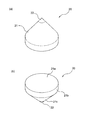
図1及び図2を用いて地盤補強用マット1の構成を説明する。図1は地盤補強用マット1の下方からの斜視図である。図2は地盤用マット1の補強用ブロック20の斜視図であり、(a)が下方からの斜視図、(b)が上方からの斜視図である。
(Configuration of soft ground mat 1)
The structure of the
図1に示すように、本実施形態の地盤補強用マット1は、複数の補強用ブロック20と、補強用ブロック20を一体的に接着固定するためのシート10とから構成される。補強用ブロック20は、シート10に対して整列して配置され、接着体または固定体により一体的に固定されている。
As shown in FIG. 1, the
接着体は、補強用ブロックとシートを相互にアンカー効果及び/又は化学的効果で接着するのもであり、敷設時及び敷設後補強用ブロックに対する荷重等により補強用ブロックがシートより剥離しなければ、任意の材質のものを用いることができる。接着体としては、例えば、水硬性セメント組成物等、主に無機材料からなるもの、樹脂系接着剤等、主に有機材料からなるもの、及びポリマーセメントモルタル、樹脂モルタル等、無機材料及び有機材料からなるもの用いることができる。水硬性セメントとしては、セメント、砂、砂利、減水剤等を配合したコンクリートでも砂利の無いモルタルでもよい。 The bonded body is used to bond the reinforcing block and the sheet to each other with an anchor effect and / or a chemical effect. When the reinforcing block does not peel off from the sheet due to a load on the reinforcing block during and after laying. Any material can be used. Adhesives include, for example, hydraulic cement compositions and the like mainly composed of inorganic materials, resin-based adhesives and the like mainly composed of organic materials, and polymer cement mortars and resin mortars, and inorganic and organic materials. Can be used. The hydraulic cement may be cement, sand, gravel, concrete mixed with a water reducing agent, or mortar without gravel.
樹脂系接着剤としては、エポキシ樹脂、ウレタン樹脂、アクリル樹脂、シリコン樹脂、エポキシアクリレート樹脂、フェノール樹脂等の熱硬化性樹脂を用いたもの、ポリアミド樹脂、ポリエステル樹脂、エチレンビニルアルコール樹脂等の熱可塑性樹脂を用いたものや、スチレンブタジエンゴム、クロロプレンゴム、ブチルゴム等合成ゴムを用いたもの等を用いることができ、強度、硬化性の優れたエポキシ樹脂が好ましく用いられる。 Resin adhesives include those using thermosetting resins such as epoxy resins, urethane resins, acrylic resins, silicone resins, epoxy acrylate resins, phenol resins, and thermoplastics such as polyamide resins, polyester resins, and ethylene vinyl alcohol resins. Those using a resin, those using a synthetic rubber such as styrene butadiene rubber, chloroprene rubber, butyl rubber, etc. can be used, and an epoxy resin excellent in strength and curability is preferably used.
固定体としては、シートと補強用ブロックを機械的に固定できるものであれば任意のものを用いることができ、金属製または樹脂製のアンカーピン、ボルト、フック等を用いることができる。また、接着体と固定体を複合して用いることもできる。 As the fixed body, any member can be used as long as the sheet and the reinforcing block can be mechanically fixed, and metal or resin anchor pins, bolts, hooks, and the like can be used. Moreover, an adhesive body and a fixed body can be used in combination.
シート10は、織物又は不織布からなる布製シートであり、水はけを良くするため、水を通すものであることが好ましい。また、シート10は、長さ方向の引張強度が固定用ブロック20の重量の2倍以上であり、前記補強用ブロックを接着したマット両端を把持して吊り揚げ、敷設して、マットの両端の把持を無くした後、マットの伸びが補強用ブロック頭部の側面部の長さ以下であるものが好ましく、伸びを小さくすることにより、敷設後の各補強用ブロック天面の平坦化を確保することができる。このように、シートの引張強度を強くし、シートの伸びを小さくすることで、補強用ブロックを安定して保持することができる。
The
この布製シートはポリエステル繊維、ナイロン繊維、ポリエチレン繊維、ポリプロピレン繊維の汎用繊維、炭素繊維、芳香族ポリアミド等の機能性繊維及び天然、再生化学繊維等で単独及び組み合わせでよく、織物は平織、綾織、メッシュ等どのような組織でもよく、不織布の場合は単独では一般的に伸びが大きいので、不織布内に織物を入れた物、不織布を糸でステッチ加工等を行ない、上記の高い引張強さ及び低い伸びを有するものであればよい。 This fabric sheet may be a single fiber or a combination of functional fibers such as polyester fibers, nylon fibers, polyethylene fibers, polypropylene fibers, carbon fibers, aromatic polyamides, and natural and recycled chemical fibers. Any structure, such as a mesh, may be used. In the case of a non-woven fabric, since the elongation is generally large by itself, the woven fabric is put in the non-woven fabric, the non-woven fabric is stitched with yarn, etc., and the above high tensile strength and low Any material having elongation may be used.
また、孔有り樹脂シートを延伸して厚み3mm以下であたかもメッシュ状織物のように柔軟性があり、伸びの少ないシートでもよい。シートの伸び率は破断時で30%以下、好ましくは25%以下程度が好ましい。 Further, the resin sheet with holes may be stretched to have a thickness of 3 mm or less as if it is a flexible and flexible sheet like a mesh woven fabric. The elongation percentage of the sheet is 30% or less, preferably about 25% or less at break.
補強用ブロック20は、図2に示すように、下方が円錐状に形成され、上方が円柱状に形成される。補強用ブロック20の材質は、下方の先端部22は通常上方部分21と同材質、もしくは軟弱地盤に硬い石等があり上方部分21が欠ける恐れが懸念される時は、先端部22以外の上方部分21とで材質が異なる。具体的には、上方部分21は圧縮力に強いコンクリートが用いられ、下方の先端部22は引張力が強く弾性のある金属又は樹脂にて構成する。
As shown in FIG. 2, the reinforcing
このように、上方部分21をコンクリートで構成すると、上部の建物等からかかる圧縮力に耐えることができ、上方部分21部分の割れを防止する。また、引張力が強く弾性のある材質で先端部22を構成すると、先端部22が、敷設時において地面から受ける応力に適度に対応することで、先端部22の割れを防止することができる。
Thus, if the
補強用ブロック20の上方部分21は、図2(b)に示すように、平らな天面21aと、天面21aから垂下することによって構成される円柱状の側面21bと、円錐の側面であるテーパ面21cとが形成される。ここで、側面21bが円柱状であることで、軟弱地盤用マット1を敷設するとき、隣接する補強用ブロック20が互いに当接すると、断面が垂直方向に伸びる側面と側面とが当接することになる。すると、互いに上下方向にずれる力が働かず、隣接する補強用ブロック20が上下方向にずれることがない。このため、補強用ブロック20の天面21aの姿勢を水平に保つことができる。
As shown in FIG. 2B, the
上方のテーパ面21c及び下方の先端部22の側面は、上方に行くに従って徐々に径が大きくなるようテーパ状に構成されている。このように構成すると、上載加重を分散し且つ地盤表面の圧密を促進し地盤に対する沈下を抑制することができるため、著しく短い時間で地盤を安定させることができる。
The side surfaces of the upper tapered
(軟弱地盤補強用マット1を用いた地盤安定化工法)
図3及び図4を用いて軟弱地盤補強用マット1を用いた地盤安定化工法を説明する。図3は軟弱地盤補強用マット1の敷設時の状態示す斜視図である。
(Ground stabilization method using soft ground reinforcement mat 1)
A ground stabilization method using the soft
本実施形態における地盤安定化工法にて施工する場合、まずその前段階として、軟弱地盤補強用マット1を作成する。
When construction is performed by the ground stabilization method in the present embodiment, first, the soft
軟弱地盤補強用マット1を作成するにあたり、まず、図1に示すように、シート10上に補強用ブロック20を整列配置する。ここで、補強用ブロック20は、隣接する補強用ブロック20の隙間をなるべくなくするように、整列して配置されるようにする。そして、補強用ブロック20の上方部分21の天面21aとシート10との間に接着剤を塗布する。この接着剤はシートの材質に対してもコンクリートに対しても接着することが可能なものを使用する。
In creating the soft
軟弱地盤補強用マット1の作成は、敷設する地盤がある現場で行うことも可能であるが、工場で予め行ってもよい。工場で行うことで、軟弱地盤補強用マット1の大きさや補強用ブロック20の重量等の選択が容易にできる。また、補強用ブロック20の配置位置の管理をより正確に行うことができる。このため、多様で且つ品質の高い軟弱地盤補強用マット1を作成することができる。
The creation of the soft
上述のように作成した軟弱地盤用マット1を軟弱地盤に敷設する際には、地盤の平坦化の為に軟弱地盤上に砕石を捲きだし、その上に軟弱地盤補強用マット1を載置する。軟弱地盤補強用マット1を載置する際には、まず、図3に示すように、軟弱地盤補強用マット1のシート10が上になり、補強用ブロック20が下になり、補強用ブロック20の先端部22が地盤に向くように配置する(載置段階)。
When the
次に、各補強用ブロック20の天面21aの上方にあたる位置から、シート10を介して矢印方向に荷重を加える。これにより、各補強用ブロック20が地盤上に差し込まれ、軟弱地盤補強用マット1が固定される(固定段階)。
Next, a load is applied in the direction of the arrow through the
以上のように、本実施形態の地盤安定化工法によれば、従来のような多数の丸太の筏組、や杭打ち・ロープ連結・土木シートを敷設する作業をしなくともよいため、手間がかからない。また、補強用ブロック20の下方の先端部22は、尖った形状であるため、差し込みやすく、且つ沈下をしにくい。このため、確実に軟弱地盤を安定化させることができる。
As described above, according to the ground stabilization method of the present embodiment, it is not necessary to perform the work of laying a large number of log rigging, pile driving, rope connection, and civil engineering sheet as in the conventional case. It does not take. Moreover, since the front-end | tip
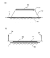
軟弱地盤補強用マット1を地盤に敷設した状態を図4を用いて説明する。図4は軟弱地盤補強用マット1の使用状態を示す断面図である。
A state where the soft
図4においては、軟弱地盤補強用マット1の上に構成するものとして、軟弱地盤補強道路を例示する。軟弱地盤補強用マット1の上の道路側には、路盤51、盛土53で構成される。
In FIG. 4, a soft ground reinforcement road is illustrated as what is comprised on the soft
〔他の実施形態〕
前述の実施形態においては、補強用ブロックの中心部が中実な構成であったが、これに限るものではない。図5を用いて他の実施形態を説明する。図5は他の実施形態における軟弱地盤補強用マット1に用いる補強用ブロック30を説明する断面図である。
[Other Embodiments]
In the above-described embodiment, the central portion of the reinforcing block has a solid configuration, but the present invention is not limited to this. Another embodiment will be described with reference to FIG. FIG. 5 is a cross-sectional view illustrating a reinforcing
図5(a)に示すように、固定用ブロック30に、天面31から突状の先端部32に至るまで貫通した貫通孔33を形成してもよい。このように構成すれば、雨が降ったときに水が貫通孔33を通って地面に排水することができるため、軟弱地盤補強用マット1の排水性能を更に向上させることができる。
As shown in FIG. 5A, a through-
また、図5(b)に示すように、貫通孔33の内周面に金属製の筒34を配設することとしてもよい。この構成によれば、補強用ブロックの先端部の強度が高まる。また、金属は水を通さず、貫通孔33に入った水が下方にのみ行くため、排水性能が更に向上する。
Further, as shown in FIG. 5B, a
本発明は、軟弱地盤以外にも様々な地盤に適用することができる。 The present invention can be applied to various grounds other than soft ground.
1…軟弱地盤補強用マット、10…シート、20…補強用ブロック、21…上方部分、21a…天面、21b…側面、21c…テーパ面、22…先端部、31…天面、32…先端部、33…貫通孔、34…筒、50…アスファルト、51…路盤、53…路体、54…防護柵
DESCRIPTION OF
Claims (7)
前記複数の補強用ブロックの前記天面に接着体または固定体により前記複数の補強用ブロックが整列して一体的に接着または固定された、織物若しくは不織布からなる布製シート又は孔有り樹脂シートを延伸した厚み3mm以下のシートと、
を有し、前記隣接する補強用ブロックが互いに当接することを特徴とする地盤補強用マット。 In order to reinforce the ground and restrain deformation, a projecting tip and a flat top surface are formed, the head is a polygonal column or cylinder, and the projecting tip is A plurality of reinforcing blocks formed in a polygonal pyramid or conical shape ;
A plurality of reinforcing blocks are aligned and integrally bonded or fixed to the top surfaces of the plurality of reinforcing blocks by an adhesive body or a fixed body, and a fabric sheet or a resin sheet having a hole is made of woven fabric or nonwoven fabric. A sheet having a thickness of 3 mm or less ,
It has a, ground reinforcement mat, characterized in that reinforcing blocks abut each other to the adjacent.
前記地盤補強用マットの前記補強用ブロックの天面にあたる位置から荷重を加えることで当該補強用ブロックを地盤に差し込むことで地表面を拘束し固定する固定段階と、
を有することを特徴とする地盤安定化工法。 A placing step of placing the tip of the ground reinforcing mat according to any one of claims 1 to 6 toward the ground;
A fixing step of restraining and fixing the ground surface by inserting the reinforcing block into the ground by applying a load from a position corresponding to the top surface of the reinforcing block of the ground reinforcing mat;
The ground stabilization method characterized by having.
Priority Applications (1)
| Application Number | Priority Date | Filing Date | Title |
|---|---|---|---|
| JP2007284795A JP5116020B2 (en) | 2007-11-01 | 2007-11-01 | Ground reinforcement mat and ground stabilization method |
Applications Claiming Priority (1)
| Application Number | Priority Date | Filing Date | Title |
|---|---|---|---|
| JP2007284795A JP5116020B2 (en) | 2007-11-01 | 2007-11-01 | Ground reinforcement mat and ground stabilization method |
Publications (2)
| Publication Number | Publication Date |
|---|---|
| JP2009108660A JP2009108660A (en) | 2009-05-21 |
| JP5116020B2 true JP5116020B2 (en) | 2013-01-09 |
Family
ID=40777424
Family Applications (1)
| Application Number | Title | Priority Date | Filing Date |
|---|---|---|---|
| JP2007284795A Active JP5116020B2 (en) | 2007-11-01 | 2007-11-01 | Ground reinforcement mat and ground stabilization method |
Country Status (1)
| Country | Link |
|---|---|
| JP (1) | JP5116020B2 (en) |
Families Citing this family (5)
| Publication number | Priority date | Publication date | Assignee | Title |
|---|---|---|---|---|
| JP5711474B2 (en) * | 2009-06-26 | 2015-04-30 | 旭化成ジオテック株式会社 | Sheet for block mat and block mat using the sheet |
| JP5178766B2 (en) * | 2010-03-31 | 2013-04-10 | 株式会社アドヴァンス | Formwork for manufacturing ground reinforcement mats |
| JP5178765B2 (en) * | 2010-03-31 | 2013-04-10 | 株式会社アドヴァンス | Manufacturing method of ground reinforcement mat |
| JP2012067554A (en) * | 2010-09-27 | 2012-04-05 | Asahi-Kasei Geotech Kk | Sheet for block mat and block mat using sheet |
| KR101223525B1 (en) | 2011-12-14 | 2013-01-21 | 현대중공업 주식회사 | The foundation a method of construction of sea the infrastructure |
Family Cites Families (2)
| Publication number | Priority date | Publication date | Assignee | Title |
|---|---|---|---|---|
| JPS6034641B2 (en) * | 1979-05-14 | 1985-08-09 | 松井 鈴子 | Mat with top-shaped protrusions |
| JPS6016612A (en) * | 1983-07-06 | 1985-01-28 | Maikoma Seven:Kk | Strengthening and stabilization of surface layer of ground and block therefor |
-
2007
- 2007-11-01 JP JP2007284795A patent/JP5116020B2/en active Active
Also Published As
| Publication number | Publication date |
|---|---|
| JP2009108660A (en) | 2009-05-21 |
Similar Documents
| Publication | Publication Date | Title |
|---|---|---|
| KR101152265B1 (en) | Prestressed bored pile construction method and structures | |
| JP5116020B2 (en) | Ground reinforcement mat and ground stabilization method | |
| KR20130045672A (en) | Structure for supporting guard rail and constructing method thereof | |
| EP0516942B1 (en) | Method and device for stabilising friction soils and bordering cohesive soils | |
| JP2018184722A (en) | Levee-back butt reinforcement structure, levee-back butt reinforcement construction method, and levee-back butt reinforcement block mat | |
| JP5711474B2 (en) | Sheet for block mat and block mat using the sheet | |
| KR100926300B1 (en) | Pile reinforcement bearing structure and construction method | |
| KR20100007721A (en) | Reinforcement | |
| KR101378123B1 (en) | Retaining Wall Having Natural Rock And Construction Method Thereof | |
| KR102506979B1 (en) | Socket Structure for Blast-Stone Wall Fixture of Earth Cutting Part, and Blast-Stone Wall Construction Method by Using This | |
| CN114396051B (en) | Construction method for foundation pit slope excavation and supporting structure | |
| JP2012067554A (en) | Sheet for block mat and block mat using sheet | |
| KR100960610B1 (en) | Reinforcing structure of head part in steel pipe pile for dispersing external force | |
| CN211227880U (en) | Expansive soil limited deformation anti-upwarp foundation structure | |
| KR20100069143A (en) | Extended reinforcing plate using glass fiber and phc pile with the same | |
| KR20200124511A (en) | Mat for soil reinforcing and soil reinforcing method the same | |
| JP4553190B2 (en) | Formwork device for fabric foundation | |
| JP2007039974A (en) | Reinforcing bar slope work | |
| JP4538822B1 (en) | Dyke reinforcement mat and dike reinforcement method | |
| JP3837669B2 (en) | Filling stabilization method on soft ground | |
| JP7668435B1 (en) | Artificial retaining wall construction method | |
| CN217632521U (en) | Upward type orifice anchoring device mounted after underground engineering clings to surrounding rock | |
| KR102559018B1 (en) | PHC Pile with Impact Reduction Performance | |
| JP4882895B2 (en) | Reinforcement method of concrete support foundation | |
| KR102336054B1 (en) | Concrete block shock absorber of ground anchor system |
Legal Events
| Date | Code | Title | Description |
|---|---|---|---|
| A621 | Written request for application examination |
Free format text: JAPANESE INTERMEDIATE CODE: A621 Effective date: 20091120 |
|
| RD02 | Notification of acceptance of power of attorney |
Free format text: JAPANESE INTERMEDIATE CODE: A7422 Effective date: 20100528 |
|
| A711 | Notification of change in applicant |
Free format text: JAPANESE INTERMEDIATE CODE: A711 Effective date: 20100531 |
|
| A521 | Request for written amendment filed |
Free format text: JAPANESE INTERMEDIATE CODE: A821 Effective date: 20100531 |
|
| A521 | Request for written amendment filed |
Free format text: JAPANESE INTERMEDIATE CODE: A523 Effective date: 20100729 |
|
| A711 | Notification of change in applicant |
Free format text: JAPANESE INTERMEDIATE CODE: A711 Effective date: 20110210 |
|
| A521 | Request for written amendment filed |
Free format text: JAPANESE INTERMEDIATE CODE: A821 Effective date: 20110210 |
|
| A977 | Report on retrieval |
Free format text: JAPANESE INTERMEDIATE CODE: A971007 Effective date: 20111026 |
|
| A131 | Notification of reasons for refusal |
Free format text: JAPANESE INTERMEDIATE CODE: A131 Effective date: 20111206 |
|
| A521 | Request for written amendment filed |
Free format text: JAPANESE INTERMEDIATE CODE: A523 Effective date: 20120202 |
|
| TRDD | Decision of grant or rejection written | ||
| A01 | Written decision to grant a patent or to grant a registration (utility model) |
Free format text: JAPANESE INTERMEDIATE CODE: A01 Effective date: 20120911 |
|
| A01 | Written decision to grant a patent or to grant a registration (utility model) |
Free format text: JAPANESE INTERMEDIATE CODE: A01 |
|
| A61 | First payment of annual fees (during grant procedure) |
Free format text: JAPANESE INTERMEDIATE CODE: A61 Effective date: 20121011 |
|
| R150 | Certificate of patent or registration of utility model |
Ref document number: 5116020 Country of ref document: JP Free format text: JAPANESE INTERMEDIATE CODE: R150 Free format text: JAPANESE INTERMEDIATE CODE: R150 |
|
| FPAY | Renewal fee payment (event date is renewal date of database) |
Free format text: PAYMENT UNTIL: 20151026 Year of fee payment: 3 |
|
| S111 | Request for change of ownership or part of ownership |
Free format text: JAPANESE INTERMEDIATE CODE: R313114 |
|
| R350 | Written notification of registration of transfer |
Free format text: JAPANESE INTERMEDIATE CODE: R350 |
|
| R250 | Receipt of annual fees |
Free format text: JAPANESE INTERMEDIATE CODE: R250 |
|
| R250 | Receipt of annual fees |
Free format text: JAPANESE INTERMEDIATE CODE: R250 |
|
| S111 | Request for change of ownership or part of ownership |
Free format text: JAPANESE INTERMEDIATE CODE: R313115 |
|
| R350 | Written notification of registration of transfer |
Free format text: JAPANESE INTERMEDIATE CODE: R350 |
|
| R250 | Receipt of annual fees |
Free format text: JAPANESE INTERMEDIATE CODE: R250 |
|
| R250 | Receipt of annual fees |
Free format text: JAPANESE INTERMEDIATE CODE: R250 |
|
| R250 | Receipt of annual fees |
Free format text: JAPANESE INTERMEDIATE CODE: R250 |
|
| R250 | Receipt of annual fees |
Free format text: JAPANESE INTERMEDIATE CODE: R250 |
|
| R250 | Receipt of annual fees |
Free format text: JAPANESE INTERMEDIATE CODE: R250 |
|
| R250 | Receipt of annual fees |
Free format text: JAPANESE INTERMEDIATE CODE: R250 |
|
| R250 | Receipt of annual fees |
Free format text: JAPANESE INTERMEDIATE CODE: R250 |
|
| R250 | Receipt of annual fees |
Free format text: JAPANESE INTERMEDIATE CODE: R250 |
|
| R250 | Receipt of annual fees |
Free format text: JAPANESE INTERMEDIATE CODE: R250 |