JP5116534B2 - Method for manufacturing network structure composite and method for manufacturing wearing article including network structure composite - Google Patents
Method for manufacturing network structure composite and method for manufacturing wearing article including network structure composite Download PDFInfo
- Publication number
- JP5116534B2 JP5116534B2 JP2008092710A JP2008092710A JP5116534B2 JP 5116534 B2 JP5116534 B2 JP 5116534B2 JP 2008092710 A JP2008092710 A JP 2008092710A JP 2008092710 A JP2008092710 A JP 2008092710A JP 5116534 B2 JP5116534 B2 JP 5116534B2
- Authority
- JP
- Japan
- Prior art keywords
- sheet
- mesh structure
- structure member
- network structure
- portions
- Prior art date
- Legal status (The legal status is an assumption and is not a legal conclusion. Google has not performed a legal analysis and makes no representation as to the accuracy of the status listed.)
- Expired - Fee Related
Links
Images


Landscapes
- Absorbent Articles And Supports Therefor (AREA)
- Manufacturing Of Multi-Layer Textile Fabrics (AREA)
Description
この発明は、網目構造複合体の製造方法に関し、さらに詳しくは使い捨てのおむつ、排便トレーニングパンツ、失禁ブリーフ等の着用物品に使用される網目構造複合体および、網目構造複合体を含む着用物品の製造方法に関する。 The present invention relates to a method for producing a mesh structure composite, and more specifically, a mesh structure composite used for a wear article such as a disposable diaper, a defecation training pant, an incontinence brief, and a wear article including the mesh structure composite. Regarding the method.
従来、使い捨てのおむつにおいて、網目状のパネルを有するものとして、例えば特開2001−276121号公報(特許文献1)が公知である。この特許文献1によれば、透液性表面シートと、不透液性裏面シートと、これら表裏面シートの間に介在する吸液性コアとを有するおむつにおいて、表面シートの身体側に網目状でシート状のパネルが取り付けられている。パネルは、網目を形成する障壁部と、障壁部の間に形成されたパネルを貫通する開口部とを備え、排泄された便等が開口部で捕集されるようにしている。開口部で便を捕集することができるので、パネルの着用者側に便が残留せず、便が着用者に接触するのを抑制することができる。
上記のような従来のおむつにおいては、パネルに開口部を形成してから、表面シートに取り付けていた。すなわち、パネルを形成する工程と、パネルを表面シートに取り付ける工程とは別々であったので、その分製造工程数が多くなり、製造時間の増加、製造コストの増加が懸念される。
パネルが着用者の肌に接触した際の刺激を抑制しようとすれば、障壁部の嵩高を大きくすることが考えられる。しかし、嵩高の大きいパネルを表面シートに取り付ける際に、障壁部がつぶれることが懸念される。
In the conventional diaper as described above, an opening is formed in the panel and then attached to the top sheet. That is, since the process of forming the panel and the process of attaching the panel to the top sheet are separate, the number of manufacturing processes increases correspondingly, and there is a concern about an increase in manufacturing time and an increase in manufacturing cost.
If it is going to suppress the irritation | stimulation at the time of a panel contacting a wearer's skin, it is possible to enlarge the bulkiness of a barrier part. However, when attaching a bulky panel to the top sheet, there is a concern that the barrier portion will collapse.
この発明では、製造時間および製造コストを低減することができる網目構造複合体の製造方法およびこの網目構造複合体を含む着用物品の製造方法を課題とする。 This invention makes it a subject to the manufacturing method of the network structure composite which can reduce manufacturing time and manufacturing cost, and the manufacturing method of the wearing article containing this network structure composite.
この発明は、対向する一方の面および他方の面を有し前記一方の面から前記他方の面へと貫通する複数の通路と、前記通路を形成する隔壁とを含む網目構造部材と、前記網目構造部材の前記いずれかの面に積層される保持シート部材とを含み、縦方向および横方向を有する網目構造複合体の製造方法の改良に関わる。 The present invention provides a mesh structure member including a plurality of passages having one surface and the other surface facing each other and penetrating from the one surface to the other surface, and a partition wall forming the passage, and the mesh And a holding sheet member laminated on any one of the surfaces of the structural member, and relates to an improvement in a method for producing a network structure composite having a vertical direction and a horizontal direction.
この発明は前記網目構造複合体の製造方法において、前記網目構造部材は、前記隔壁を形成し前記縦方向に延びる複数のシート片と、前記シート片を互いに接合するとともに前記縦方向に離間して存在する複数の接合部とを含む。前記複数のシート片を積層し、積層面に前記接合部を形成し、前記接合部を積層方向に隣接する前記接合部と互いに重ならない位置に前記縦方向にずらして形成する工程と、積層方向両端に位置する一方の前記シート片と他方の前記シート片とに、前記保持シート部材の一方の側縁と他方の側縁とをそれぞれ接合する工程と、前記保持シート部材の前記一方の側縁と前記他方の側縁とを離間させるように開いて前記通路を形成する工程とを含み、前記通路の形成と同時に前記網目構造部材と前記保持シート部材とが積層されることを特徴とする。 The present invention provides the method for manufacturing a mesh structure composite, wherein the mesh structure member includes a plurality of sheet pieces that form the partition walls and extend in the longitudinal direction, and the sheet pieces are joined to each other and spaced apart in the longitudinal direction. A plurality of existing joints. Laminating the plurality of sheet pieces, forming the joining portion on a lamination surface, and forming the joining portion by shifting in the vertical direction at a position that does not overlap with the joining portions adjacent to each other in the lamination direction; Joining one side edge and the other side edge of the holding sheet member to the one sheet piece and the other sheet piece located at both ends, respectively, and the one side edge of the holding sheet member And the step of forming the passage so as to be spaced apart from the other side edge, and the mesh structure member and the holding sheet member are laminated simultaneously with the formation of the passage.
好ましい実施態様のひとつとして、前記保持シート部材は、前記横方向に離間して前記縦方向に延びる一対の両側シート部を含み、一方の前記シート部を前記網目構造部材の一方の前記シート片に接合し、他方の前記シート部を前記網目構造部材の他方の前記シート片に接合する。 As one of preferred embodiments, the holding sheet member includes a pair of both side sheet portions that are separated in the lateral direction and extend in the longitudinal direction, and one of the sheet portions is attached to one sheet piece of the mesh structure member. The other sheet part is joined to the other sheet piece of the mesh structure member.
好ましい実施形態のひとつとして、前記保持シート部材は、前記両側シート部間を互いにつなぐ両端シート部を含み、前記保持シート部材を、前記両側シート部を互いに重ね合わせて折り畳む工程をさらに含み、前記両側シート部の折り畳んだ内面側を前記網目構造部材のシート片に接合する。 As one of preferred embodiments, the holding sheet member includes both end sheet portions that connect the both side sheet portions to each other, and further includes a step of folding the holding sheet member so that the both side sheet portions overlap each other, The folded inner surface side of the sheet part is joined to the sheet piece of the mesh structure member.
この発明は、対向する一方の面および他方の面を有し前記一方の面から前記他方の面へと貫通する複数の通路と、前記通路を形成する隔壁とを含む網目構造部材と、前記網目構造部材の前記いずれかの面に積層される保持シート部材と、縦方向および横方向とを有する網目構造複合体を含む着用物品の製造方法であって、前記網目構造部材は、前記隔壁を形成し前記縦方向に延びる複数のシート片と、前記シート片を互いに接合するとともに前記縦方向に離間して存在する複数の接合部とを含み、前記複数のシート片を積層し、積層面に前記接合部を形成し、前記接合部を積層方向に隣接する前記接合部と互いに重ならない位置に前記縦方向にずらして形成する工程と、積層方向両端に位置する前記一方のシート片と前記他方のシート片とに、前記保持シート部材の一方の側縁と他方の側縁とをそれぞれ接合する工程と、前記保持シート部材の前記一方の側縁と前記他方の側縁とを離間させるように開いて前記通路を形成する工程と、前記通路の形成と同時に前記網目構造部材と前記保持シート部材とが積層される工程と、身体側に位置する内面シートおよび着衣側に位置する外面シートと、これら内外面シートの間に位置する吸液構造体とを含むシャーシの身体側に前記網目構造複合体を接合する工程とを含むことを特徴とする。 The present invention provides a mesh structure member including a plurality of passages having one surface and the other surface facing each other and penetrating from the one surface to the other surface, and a partition wall forming the passage, and the mesh A method of manufacturing a wearing article including a holding sheet member laminated on any one surface of a structural member, and a network structure composite having a longitudinal direction and a lateral direction, wherein the mesh structure member forms the partition wall A plurality of sheet pieces extending in the longitudinal direction; and a plurality of joint portions that join the sheet pieces to each other and are spaced apart from each other in the longitudinal direction, laminating the plurality of sheet pieces, Forming a joining portion, forming the joining portion by shifting in the longitudinal direction at a position that does not overlap with the joining portions adjacent to each other in the stacking direction, and the one sheet piece and the other sheet located at both ends in the stacking direction. With sheet pieces The step of joining one side edge and the other side edge of the holding sheet member respectively, and the one side edge of the holding sheet member and the other side edge are opened so as to be spaced apart to form the passage. A step of laminating the mesh structure member and the holding sheet member simultaneously with the formation of the passage, an inner sheet positioned on the body side, an outer sheet positioned on the clothing side, and the inner and outer sheets characterized in that it comprises a step of joining the network structure complex body side of the chassis including a liquid-absorbent structure located on.
好ましい実施態様のひとつとして、前記網目構造複合体は、前記網目構造部材をシャーシ側に位置させる。 As one preferred embodiment, the network structure composite has the network structure member positioned on the chassis side.
好ましい他の実施形態のひとつとして、前記シャーシと前記網目構造複合体との間に、吸液シートを接合する工程をさらに含む。 As another preferred embodiment, the method further includes a step of joining a liquid absorbing sheet between the chassis and the network structure composite.
好ましい他の実施形態のひとつとして、前記網目構造部材の身体側に、前記縦方向に延びて前記横方向に離間する一対の漏れバリアカフを接合する工程をさらに含む。 As another preferred embodiment, the method further includes a step of joining a pair of leakage barrier cuffs extending in the longitudinal direction and spaced apart in the lateral direction to the body side of the mesh structure member.
保持シート部材の一方の側縁と他方の側縁とが離間するように開いて網目構造部材の通路を形成する工程を含むこととしたので、網目構造部材の通路が形成されるのと同時に、保持シート部材を網目構造部材に接合することができる。したがって、通路を別に形成してから、網目構造部材をシートに接合する場合に比べて、工程数を減少することができ、製造コストの軽減が可能となる。また、網目構造部材は、シート片を積層した状態で搬送されるので、通路が形成された網目構造部材を搬送する場合に比べて製品の形状を一定に維持することができる。すなわち、通路が形成された後に網目構造部材を搬送する場合には、搬送中に通路が変形したりしてその形状を維持することが困難となる可能性があるが、これを抑制することができ、安定して網目構造部材を搬送することができる。
積層したシート片を開いて網目構造部材の通路を形成しながら、これを保持シート部材に積層することができるので、網目構造部材を保持シートに積層する際に、網目構造部材の隔壁がつぶれてしまうことがない。したがって、網目構造部材の嵩高が大きくしても網目がつぶれることなく、着用者の肌に対する刺激を低減することができる。
Since it includes the step of forming the network structure member passage so that one side edge and the other side edge of the holding sheet member are spaced apart from each other, the network structure member passage is formed at the same time. The holding sheet member can be joined to the mesh structure member. Therefore, the number of steps can be reduced and the manufacturing cost can be reduced as compared with the case where the mesh structure member is joined to the sheet after the passage is formed separately. Moreover, since the mesh structure member is conveyed in a state where the sheet pieces are laminated, the shape of the product can be maintained constant as compared with the case where the mesh structure member having the passages is conveyed. That is, when the mesh structure member is transported after the passage is formed, the passage may be deformed during transportation and it may be difficult to maintain the shape, but this may be suppressed. The mesh structure member can be stably conveyed.
While the laminated sheet pieces are opened to form a mesh structure member passage, it can be laminated on the holding sheet member. Therefore, when the mesh structure member is laminated on the holding sheet, the partition wall of the mesh structure member is crushed. There is no end. Therefore, even if the bulkiness of the mesh structure member is increased, the irritation to the wearer's skin can be reduced without collapsing the mesh.
保持シート部材は、横方向に離間する一対の両側シート部を含み、一方のシート部を網目構造部材の一方のシート片に接合し、他方のシート部を網目構造部材の他方のシート片に接合することとしたので、両側シート部の間に開口部が形成され、開口部を介して網目構造部材の通路が露出する。したがって、保持シート部材が着用者側に位置する場合であっても、網目構造部材を着用者側に位置させることができる。また、両側シート部の離間距離によって、網目構造部材の通路の面積を容易に調整することができる。 The holding sheet member includes a pair of laterally spaced sheet parts, one sheet part is joined to one sheet piece of the mesh structure member, and the other sheet part is joined to the other sheet piece of the mesh structure member. Therefore, an opening is formed between the sheet portions on both sides, and the passage of the mesh structure member is exposed through the opening. Therefore, even when the holding sheet member is located on the wearer side, the mesh structure member can be located on the wearer side. Moreover, the area of the channel | path of a mesh structure member can be easily adjusted with the separation distance of a sheet | seat part on both sides.
保持シート部材が、両側シート部を互いに重ね合わせて折り畳まれる工程をさらに含み、両側シート部の折り畳んだ内面側を網目構造部材のシート片に接合することとしたので、折り畳んだ保持シート部材を広げるだけで、網目構造部材の通路を形成することができる。両端シート部によって両側シート部間の距離が規制されているので、両端シート部間の距離が変動することなく、安定して網目構造部材の通路を形成することができる。 The holding sheet member further includes a step of folding the both side sheet portions on top of each other, and the folded inner surface side of the both side sheet portions is joined to the sheet piece of the mesh structure member, so that the folded holding sheet member is expanded. Only by this, the passage of the mesh structure member can be formed. Since the distance between both side sheet parts is regulated by the both end sheet parts, the path of the mesh structure member can be formed stably without the distance between the both end sheet parts changing.
内外面シートの間に位置する吸液構造体を含むシャーシの身体側に、網目構造複合体を接合する工程を含むこととしたので、着用物品に網目構造複合体を形成することができる。網目構造複合体で排泄物等を捕集し、この排泄物等の水分を吸液構造体で吸収することができる。網目構造部材で排泄物の流動を抑制し、水分を速やかに吸液構造体へと導くことができるので、排泄物等が着用者の肌に付着することによる肌トラブルを抑制することができる。 Since the step of joining the network structure composite to the body side of the chassis including the liquid absorbing structure located between the inner and outer surface sheets is included, the network structure composite can be formed on the wearing article. It is possible to collect excrement and the like with the network structure complex, and to absorb moisture such as excrement with the liquid absorption structure. Since the flow of excrement can be suppressed by the mesh structure member and moisture can be promptly guided to the liquid absorption structure, skin troubles caused by adhering excrement etc. to the skin of the wearer can be suppressed.
網目構造複合体は、網目構造部材をシャーシ側に位置させ、保持シート部材を着用者側に位置させることとしたので、網目構造部材の横方向両側縁は、保持シート部材によって押さえつけられ、網目構造部材の両側縁によって肌トラブルが発生するのを抑制することができる。 Since the mesh structure composite has the mesh structure member positioned on the chassis side and the holding sheet member positioned on the wearer side, both lateral edges of the mesh structure member are pressed by the holding sheet member, and the mesh structure It is possible to suppress the occurrence of skin troubles due to both side edges of the member.
シャーシと網目構造複合体との間に、吸液シートを接合する工程をさらに含むこととしたので、網目構造部材によって捕集された排泄物等に含まれる水分が速やかに吸収される。例えば網目構造複合体をおむつに使用した場合には、排泄された軟便の水分を速やかに吸収し、固形分と分離することによって、軟便が着用者の肌に付着して肌トラブルが発生するのを抑制することができる。 Since the step of joining the liquid-absorbing sheet is further included between the chassis and the mesh structure composite, moisture contained in excreta and the like collected by the mesh structure member is quickly absorbed. For example, when a network structure complex is used for a diaper, the moisture of the excreted loose stool is quickly absorbed and separated from the solid content, so that the loose stool adheres to the skin of the wearer and skin trouble occurs. Can be suppressed.
網目構造部材の身体側に、縦方向に延びて横方向に離間する一対の漏れバリアカフを接合することとしたので、体液が横方向に漏れるのを抑制することができる。体液は網目構造部材によってその流動性が低下しているので、より一層、横方向への漏れが抑制される。 Since a pair of leak barrier cuffs extending in the vertical direction and spaced apart in the horizontal direction are joined to the body side of the mesh structure member, it is possible to suppress body fluid from leaking in the horizontal direction. Since the fluidity of the body fluid is reduced by the mesh structure member, leakage in the lateral direction is further suppressed.
網目構造複合体を着用物品に適用した場合について、この発明の一例を説明する。
<第1の実施形態>
An example of the present invention will be described for the case where the network structure composite is applied to a worn article.
<First Embodiment>
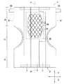
図1はおむつ1の平面図であり、説明のためにその一部を破断させている。図示したように、おむつ1は、いわゆるオープン型のものであり、吸液性のシャーシ2と網目構造部材3と網目構造部材3を被覆する被覆シート4と漏れバリアカフ5とを含む。「網目構造」とは、網目構造部材3をその上面から平面視したときの形態を含み、ハニカム構造と言い換えることも可能なものを言う。
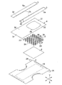
図2に示したように、おむつ1はシャーシ2の身体側に吸液シート8を介して網目構造部材3を積層し、網目構造部材3の身体側に被覆シート4を積層し、被覆シート4の身体側両側部に漏れバリアカフ5を積層している。
FIG. 1 is a plan view of the diaper 1 and a part thereof is broken for explanation. As illustrated, the diaper 1 is a so-called open type, and includes a liquid-absorbing
As shown in FIG. 2, the diaper 1 has a
図3は、シャーシ2の詳細を示した図であり、その説明のために一部を破断している。シャーシ2は、身体側内面を形成する内面シート6と着衣側外面を形成する外面シート7とを含む。シャーシ2は、前後ウエスト域9,10と前後ウエスト域9,10間に位置するクロッチ域11とを含み、これら前ウエスト域9、クロッチ域11、後ウエスト域10が連なる方向を縦方向Yとし、この縦方向Yに直交する方向を横方向Xとしている。シャーシ2は、縦方向Yに対向して横方向Xに延びる前後端縁12,13と、横方向Xに対向して縦方向Yに延びる両側縁14とを含む。両側縁14は前後ウエスト域9,10に位置する前後側縁15,16と、クロッチ域11に位置するレッグ側縁17とを有している。シャーシ2は、レッグ側縁17において横方向Xの寸法を二等分する縦中心線P−Pに向かって湾曲し、全体として砂時計型を形成している。
FIG. 3 is a diagram showing details of the
シャーシ2は、前後端縁12,13において横方向Xに延びる前後ウエスト弾性部材18,19が取り付けられている。前後ウエスト弾性部材18,19は、内外面シート6,7の間に介在し、横方向Xに伸長状態で図示しない接着剤によって取り付けられている。クロッチ域11には、レッグ側縁17に沿って延びる複数条のレッグ弾性部材20が取り付けてられている。レッグ弾性部材20は、内外面シート6,7の間に介在し、伸長状態で図示しない接着剤によって取り付けられている。
Front and rear waist
内外面シート6,7の間には吸液構造体21を介在させている。吸液構造体21は、フラッフパルプと高吸収性ポリマー粒子との混合物等を有する吸液性芯材22と、この芯材22を包むティッシュペーパ等の拡散シート23とを含む。吸液構造体21と外面シート7との間には、不透液性の漏れバリアシート24を介在させ、吸液構造体21からおむつ1外への尿等の排泄物の漏れを抑制している。
シャーシ2の後側縁16には、テープファスナ25を形成し、このテープファスナ25を前ウエスト域9の外面シート7に離脱可能に係合することによって、おむつ1が立体形状を形成するようにしている。このようにおむつ1が立体形状になったときには、前後端縁12,13によってウエスト開口を形成し、レッグ側縁17によってレッグ開口が形成される。
A
A
図2に示したように、網目構造部材3は、横方向Xに対向し縦方向Yに延びる両側縁33と、縦方向Yに対向し横方向Xに延びる両端縁34とを含む。網目構造部材3は、クロッチ域11から後ウエスト域10にかけて配置されている。網目構造部材3は、複数の隔壁26を接合部27で接合することによって網目構造を形成し、これら隔壁26の間では網目構造部材3の身体側に位置する一方の面から着衣側に位置する他方の面へと開口しその厚さ方向に貫通する複数の通路28が形成される。
As shown in FIG. 2, the
網目構造部材3は、吸液シート8を介してシャーシ2に接合されている。吸液シート8は、シャーシ2のクロッチ域11から後ウエスト域10にかけて位置するとともに、内面シート6に接着または溶着により接合されている。吸液シート8としては、熱可塑性繊維ウェブを積層した乾式不織布を用いることによって、吸液能力を向上させている。ただし、この不織布に限定されることなく、一般的な液透過性のシートを用いることができる。
The
被覆シート4は透液性の不織布等から形成され、網目構造部材3の身体側に積層されている。被覆シート4は、その縦方向Yの長さ寸法を、シャーシ2の縦方向Yの長さ寸法とほぼ等しくなるようにし、横方向Xの長さ寸法を網目構造部材3の横方向Xの長さ寸法よりも大きくなるようにしている。被覆シート4には、開口部29が形成されている。
The
開口部29の横方向Xの両側には縦方向Yに延びる両側シート部30が形成され、縦方向Yの両端には横方向Xに延びる両端シート部31が形成される。言い換えれば、両側シート部30および両端シート部31は、一枚のシートで形成され、これらシート部30,31によって開口部29が形成される。この開口部29はクロッチ域11から後ウエスト域10にかけて配置され、開口部29から網目構造部材3が露出するように、被覆シート4を網目構造部材3に積層している。両側シート部30によって網目構造部材3の両側縁33を被覆し、両端シート部31によって両端縁34を被覆している。
Both
漏れバリアカフ5は不透液性の不織布等であって、縦方向Yに延びる一対のシートから形成されている。漏れバリアカフ5は、縦中心線P−Pに対して離間対向し、その縦方向Yの長さ寸法は、シャーシ2の長さ寸法とほぼ等しくなるようにしている。漏れバリアカフ5は基側縁5aをシャーシ2に接合し、自由側縁5bは接合していない。自由側縁5bには、この縁に沿って縦方向Yに延びるカフ弾性部材32を伸長状態で取り付けている。漏れバリアカフ5は、カフ弾性部材32の収縮力によって、基側縁5aを支点としてシャーシ2から自由側縁5bを含む部分が起立するように離間して漏れに対するバリアを形成し、便漏れ等を抑制している。
The
図4は図1のV−V線端面図、図5は図1の縦中心線P−Pにおける端面図である。図示したように、シャーシ2、吸液構造体21、吸液シート8、網目構造部材3、被覆シート4、漏れバリアカフ5が、身体側に向かって順に積層されている。網目構造部材3は、隔壁26が接着または溶着によって吸液シート8に接合され、通路28によって身体側と吸液シート8とが連通する。
被覆シート4は、両側シート部30によって網目構造部材3の側縁33を被覆し、側縁33を着衣側に押し付けるようにして接合される。被覆シート4の両端シート部31は、網目構造部材3の端縁34を被覆し、端縁34を着衣側に押し付けるようにして接合される。
4 is an end view taken along the line VV of FIG. 1, and FIG. 5 is an end view taken along the vertical center line PP of FIG. As illustrated, the
The
網目構造部材3が被覆シート4で押し付けられるので、網目構造部材3の両側縁33は被覆シート4によってつぶされて、その厚さ方向の寸法が短くなっている。このように両側縁33の厚さが薄くなることによって、起立するように離間した漏れバリアカフ5の自由側縁5bから網目構造部材3の隔壁26との離間距離を大きくすることができる。自由側縁5bから隔壁26までの離間距離が大きくなることによって、網目構造部材3で捕集された排泄物が漏れバリアカフ5を超えておむつ1外に漏れるのを抑制することができる。網目構造部材3の両端縁34は被覆シート4によってつぶされることによって、その厚さ方向の寸法が短くなり、網目構造部材3から吸液シート8、吸液構造体21への段差を小さくすることができる。段差が大きいとこれによって肌への刺激が大きくなり、肌トラブルを生じる可能性がるが、段差を小さくすることによって肌トラブルを抑制することができる。
Since the
上記のようなおむつ1を着用する場合には、被覆シート4の開口部29が着用者の肛門に位置するようにして、テープファスナ25を前ウエスト域9の外面シート7に離脱可能に係合させる。したがって、排泄された便を開口部29を介して網目構造部材3の通路28に導くことができる。通路28は隔壁26によって隔離されているので、その通路28に便を収容することができる。したがって、排泄された便の流動性が低下して、便が広い範囲で肌に付着するのを抑制することができる。さらに、便は通路28を介して吸液シート8に接触する。吸液シート8は高い吸水度を有するので、収容された便中の水分を吸液構造体21側へと速やかに移動させることができる。したがって水分の多い軟便が排泄された場合であっても、その水分を速やかに吸液構造体21で吸収することができ、肌へ軟便が逆流するのを抑制することができる。
When wearing the diaper 1 as described above, the
網目構造部材3は吸液シート8に接着または溶着によって接合されるようにしているが、吸液シート8が取り付けられていない場合には網目構造部材3をシャーシ2の内面シート6に直接接合してもよい。
The
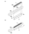
この第1の実施形態のおむつの製造方法を図6〜8に基づいて説明する。おむつは一連の製造工程において製造されるが、網目構造部材3はシート片を折り畳んだ状態で製造工程に搬送される。図6に示したように、網目構造部材3は複数の隔壁26によって形成されているが、隔壁26は縦方向Yに延びるテープ状のシート片38によって形成される。図6(a)に示したように、シート片38は互いの面を対向させて横方向Xに積層され、縦方向Yに一定間隔に配置される接合部27を形成している。接合部27は、横方向Xにおいて隣接しないようにずらして、すなわち積層方向において隣り合う接合部が互いに重ならないように形成され、接合部27と非接合部とによって千鳥パターンを画くようにしている。シート片38は、その積層方向の両端に位置する一方のシート片38aと他方のシート片38bとを含む。
The manufacturing method of the diaper of this 1st Embodiment is demonstrated based on FIGS. The diaper is manufactured in a series of manufacturing processes, and the
図6(a)の状態から、網目構造部材3を矢印Aで示したように一方のシート片38aと他方のシート片38bとを離間する方向に、すなわち横方向Xの外側に引っ張って展開させると,図6(b)に示したような通路28が形成される。網目構造部材3においては、シート片38が隔壁26となり、隔壁26の間に通路28が形成される。このような網目構造部材3は、図6(a)の積層状態で、製造工程に搬送される。
From the state of FIG. 6A, the
図7は、網目構造複合体40に吸液シート8を接合する製造工程を示した説明図である。網目構造複合体40は、網目構造部材3と保持シート部材とを含むが、この実施形態において保持シート部材は被覆シート4によって構成されている。
図7において、矢印Bはウェブの搬送方向を示しており、※1において製造工程が連続していることを示している。図示したように、被覆シート4が切断前のウェブの状態で搬送される。被覆シート4には、搬送方向に延びる接着剤41a,42aおよび41b,42bが搬送方向中心線R−Rに対称に各2条ずつ形成される。被覆シート4に示された仮想線43は、おむつひとつに使用される場合の切断線を示したものであり、接着剤41a,41b,42a,42bは仮想線43間の中心よりも搬送方向後方に位置している。
FIG. 7 is an explanatory view showing a manufacturing process for joining the liquid
In FIG. 7, an arrow B indicates the web conveyance direction, and in * 1, it indicates that the manufacturing process is continuous. As illustrated, the
接着剤41a,41b,42a,42bが塗布されたら、ローラ44によって積層状態の網目構造部材3が被覆シート4に供給される。ローラ44にはカッター45が取り付けられ、網目構造部材3を接着剤41aの長さ寸法とほぼ同じ長さに切断する。切断された網目構造部材3は、一方のシート片38aを中心線R−R側に位置する接着剤41aに重なるように搬送され、この接着剤41aによって被覆シート4に接合される。
When the
網目構造部材3が接合されると、ローラ46によってウェブ状の吸液シート8が被覆シート4に供給される。吸液シート8は、図8に示したように、あらかじめ中心線R−Rに平行の折り曲げ線47に沿って二つ折りに折り畳まれている。吸液シート8は、折り曲げ線47に平行に延びる両側縁8a,8bを含み、この両側縁8a,8bが折曲線48,49を介して外側に折り返されている。ローラ46にはカッター50が取り付けられ、ウェブ状の吸液シート8は、接着剤42aの長さ寸法とほぼ同じ長さに切断される。切断された吸液シート8は、側縁8aが接着剤42aに重なるように搬送され、被覆シート4に接合される。
When the
被覆シート4に網目構造部材3と吸液シート8とが接合されたら、被覆シート4を中心線R−Rに沿って折り畳む。すなわち、被覆シート4は中心線R−Rに平行に延びる両側縁4a,4bを含み、これら両側縁4a,4bが重なるようにして被覆シート4を折り畳む。被覆シート4の側縁4b側には、接着剤41b,42bが塗布されている。この接着剤41b,42bは接着剤41a,42bに対して中心線R−Rに関し対称である。したがって、中心線R−Rで折り畳むことによって、接着剤41a,42aと接着剤41b,42bとが、網目構造部材3および吸液シート8を介して重なる。すなわち、網目構造部材3の他方のシート片38bが接着剤41bを介して被覆シート4に接合し、吸液シート8の側縁8bが接着剤42bを介して被覆シート4に接合される。
When the
被覆シート4を折り畳んだら、中心線R−Rに沿って開口部29を形成する。開口部29は網目構造部材3および吸液シート8の搬送方向の長さ寸法よりも短くなるように形成され、折りたたんだ被覆シート4を中心線R−R側から切り欠くようにして形成される。
When the
折り畳んだ被覆シート4に開口部29が形成されたら、この被覆シート4を再び広げる。網目構造部材3の一方のシート片38aと他方のシート片38bとが被覆シート4に接合されているので、被覆シート4を広げると、網目構造部材3も広げられ図6(b)に示したように展開してシート片38の間に通路28が形成され、シート片38によって隔壁26が形成される。このようにして、網目構造複合体40が製造され、さらに網目構造複合体40に吸液シート8が取り付けられる。吸液シート8と網目構造部材3との間には図示しない接着剤を塗布し、これらを接合するようにしている。
When the
図9はシャーシ2に、吸液シート8が取り付けられた網目構造複合体40等を接合する工程について説明した図であり、矢印Bは搬送方向を示し、※2において製造工程が連続していることを示している。図示したように、シャーシ2を構成するウェブ状の外面シート7には吸液構造体21、前後ウエスト弾性部材18,19およびレッグ弾性部材20が図示しない接着剤を介して接合されている。この外面シート7に吸液構造体21および各弾性部材18〜20を介して、ローラ51によってウェブ状の内面シート6が積層される。内面シート6と外面シート7とは図示しない接着剤を介して互いに接合される。
FIG. 9 is a diagram illustrating a process of joining the
内外面シート6,7が接合されたら、内面シート6上に図7で製造された網目構造複合体40をローラ52によって積層する。このとき、網目構造複合体40に取り付けた吸液シート8が内面シート6側に位置するように積層し、図示しない接着剤によって接合する。したがって、網目構造複合体40は、被覆シート4の開口部29から網目構造部材3が露出するように取り付けられる。
When the inner and
シャーシ2に網目構造複合体40が取り付けられたら、ローラ58を介して一対の漏れバリアカフ5が供給される。漏れバリアカフ5は、被覆シート4の両側縁4a,4bを覆うようにして内面シート6に積層され、図示しない接着剤によって接合される。漏れバリアカフ5は、外側に位置する基側縁5aのみが接合され、内側に位置する自由側縁5bは接合されない。
When the
シャーシ2に漏れバリアカフ5が接合されたら、後ウエスト弾性部材19の側方にテープファスナ25を図示しない接着剤によって取り付ける。テープファスナ25を取り付けたら、シャーシ2の搬送方向両側縁2a,2bに中心線R−Rに向かって湾曲するレッグ側縁17を形成する。すなわち、内外面シート6,7を中心線R−Rに向かって切り欠くようにして、レッグ側縁17を形成する。レッグ側縁17を形成したら、仮想線53に沿って図示しないカッターで切断し、それぞれおむつ1が形成される。なお、図7の切断仮想線43と図9の切断仮想線53とは一致するように、シャーシ2と網目構造複合体40とを積層し、これらを同時に切断する。
When the
以上のような製造方法によって、一連の工程でおむつ1を製造することができ、製造時間の短縮、および製造コストの低減を図ることができる。網目構造複合体40の製造においては、網目構造部材3を折り畳んだ状態で製造工程に搬送し、これを被覆シート4に取り付けてから、網目構造が形成されるようにしたので、網目構造複合体40の製造工程において、隔壁26がつぶれて通路28が塞がれてしまうことがない。製造工程において隔壁26がつぶれることがないので、この隔壁26を嵩高にして、着用者への柔軟性を向上させることが可能である。
また、網目構造部材3の通路28を形成してから搬送することとすると、網目構造部材3を形成するシート片38a,38bが必要以上に引っ張られたりしてその形状が安定しないこともあり得るが、シート片38の積層状態で網目構造部材3を搬送するので、これを抑制することができる。
By the manufacturing method as described above, the diaper 1 can be manufactured in a series of steps, and the manufacturing time can be shortened and the manufacturing cost can be reduced. In the manufacture of the
Further, if the sheet is transported after the
被覆シート4の開口部29を形成する両側シート部30に網目構造部材3のシート片38a,38bを接合し、これらを展開するだけで、網目構造が形成されるので、この製造が容易である。しかも、両側シート部30の離間距離は両端シート部31によって規制されているので、一定の離間距離を維持することができ、製品間における網目構造部材3の通路28の大きさのばらつきを抑制することができる。両側シート部30の離間距離に応じて、網目構造部材3の通路28の大きさを調整すれば、さまざまな大きさの開口部29を有する被覆シート4に適用可能である。ただし、シート片38を12枚積層し、接合部27間の縦方向Yの距離を約30mmとした場合には、網目構造部材3の両側縁33間の距離は50mm〜70mmとすることが望ましい。
開口部29は、被覆シート4の一部をくりぬくことによって形成することができるので、他の特別な部材が必要ない。したがって、部品点数および加工点数を低減することができ、コストの低減を図り、加工安定性を向上させることができる。
Since the mesh structure is formed simply by joining the
Since the
接着剤41a,41bおよび接着剤42a,42bは接触塗工または非接触塗工のいずれによって塗布してもよい。ただし、シートの剛性が高くならないようにするには低目付で接着剤を塗布するほうが好ましく、この場合には非接触塗工を選択することができる。
The
この実施形態では、保持シート部材である被覆シート4に折り畳んだ吸液シート8を接合し、網目構造部材3の通路28の形成と同時に、網目構造部材3に吸液シート8が積層されるようにしているが、網目構造部材3の形成の後に吸液シート8を別に積層するようにしてもよい。吸液シート8を別に積層する場合には、吸液シート8を折り畳む工程を省略することができる。
保持シート部材として被覆シート4を用いているが、網目構造部材3の積層されたシート片38を広げて通路28を形成することができれば、他のシートを用いることが可能である。例えば、吸液シート等を保持シートとして使用することもできる。
<第2の実施形態>
In this embodiment, the folded liquid-absorbing
Although the
<Second Embodiment>
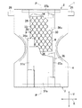
図10は第2の実施形態のおむつ1を示したものである。この第2の実施形態においては、被覆シートのみが第1の実施形態と異なり、他の部材は第1の実施形態と同様である。したがって、同様の部材についての説明を省略する。
図示したように、被覆シート35は、横方向Xに離間して縦方向Yに延びる一対の両側シート部36aおよび36bと、縦方向Yに離間して横方向Xに延びる一対の両端シート部37aおよび37bとを含む。両側シート部36a,36bと両端シート部37a,37bとは、それぞれ別のシートである。
FIG. 10 shows the diaper 1 of the second embodiment. In the second embodiment, only the covering sheet is different from the first embodiment, and other members are the same as those in the first embodiment. Therefore, the description about the same member is abbreviate | omitted.
As shown in the drawing, the covering
両側シート部36a,36bは、網目構造部材3の身体側に積層されている。一対の両側シート部36a,36bは縦中心線P−Pに対称に位置し、網目構造部材3の側縁33を覆うように内面シート6に接着または溶着によって接合されている。両端シート部37a,37bは、両側シート部36a,36bの身体側に積層されている。一対の両端シート部37a,37bは網目構造部材3の端縁34を覆うように両側シート部36a,36bに接着または溶着によって接合している。ただし、両側シート部36a,36bに重ならない部分においては、内面シート6に接合されている。
Both
両側シート部36a,36bおよび両端シート部37a,37bによって開口部を形成し、この開口部から網目構造部材3を露出させるようにしている。網目構造部材3の両側縁33および両端縁34を、両側シート部36a,36bおよび両端シート部37a,37bで覆うことによって、網目構造部材3を吸液シート8に押し付けて、浮き上がりを抑制するとともに、尿等の漏れを抑制することができる。これは第1の実施形態と同様である。
An opening is formed by the both
この第2の実施形態のおむつの製造方法を図11〜13に基づいて説明する。第1の実施形態のおむつの製造方法と同様の方法については、その説明を省略する。図11は、網目構造複合体54の製造工程と、この網目構造複合体54に吸液シート8を取り付ける工程を示したものであり、搬送方向を矢印Bで示し、※3において製造工程が連続していることを示している。この実施形態において、保持シート部材とは被覆シート35を構成する両側シート部36a,36bである。図示したように、一方のウェブ状の側シート部36aに搬送方向に延びる二条の接着剤41a,42aが塗布され、搬送される。
The manufacturing method of the diaper of this 2nd Embodiment is demonstrated based on FIGS. Description of the method similar to the method of manufacturing the diaper of the first embodiment is omitted. FIG. 11 shows the manufacturing process of the
接着剤41aにはローラ44から搬送された網目構造部材3が積層され、一方の側シート部36aに接合される。網目構造部材3は第1の実施形態で説明したとおりであり、複数のシート片38が積層された状態で供給され、その一方のシート片38aが側シート部36aに接合される。網目構造部材3は、接着剤41aとほぼ同じ長さ寸法になるようにカッター45で切断されて供給される。
The
側シート部36aに網目構造部材3が接合されたら、ローラ46によって吸液シート8が側シート部36aに供給される。吸液シート8は、第1の実施形態で説明したようにその両側縁8a,8bは折曲線48,49を介して折り曲げられている。折り曲げられた側縁8aが接着剤42aに重なるように、吸液シート8が側シート部36aに接合される。吸液シート8は接着剤42aとほぼ同じ長さ寸法になるようにカッター50で切断されて供給される。
When the
一方の側シート部36aに網目構造部材3および吸液シート8が接合されたら、ローラ55を介して他方の側シート部36bが搬送される。他方の側シート部36bには、接着剤41b,42bが塗布されている。他方の側シート部36bは、接着剤41b,42bが接着剤41a,41bに重なるように一方の側シート部36aに積層される。したがって、他方の側シート部36bの接着剤41bは網目構造部材3の他方のシート片38bに接合され、接着剤42bは吸液シート8の側縁8bに接合される。
When the
両側シート部36a,36bによって、網目構造部材3および吸液シート8が接合されたら、一方の側シート部36aを他方の側シート36bから離間させる方向に展開する。すなわち、一方の側シート部36aを中心線R−Rを跨いで反対側に移動させる。このように両側シート部36a,36bを離間させることによって、吸液シート8と両側シート部36a,36bとの間に網目構造部材3が積層されるようになる。
When the
図12は両側シート部36a,36bの間に網目構造部材3および吸液シート8が接合された状態を立体的に示した説明図である。図12(a)に示したように両側シート部36a,36bの間に網目構造部材3および吸液シート8が組み込まれ、図12(b)の矢印方向に一方の側シート部36aが引っ張られる。このように両側シート部36a,36bを離間させることによって、吸液シート8の身体側に網目構造部材3が積層され、その更に身体側に両側シート部36a,36bが積層するようになり、図11に示した網目構造複合体54が形成される。
FIG. 12 is an explanatory view three-dimensionally showing a state in which the
図13は、シャーシ2に網目構造複合体54等を接合する工程を示したものであり、矢印Bは搬送方向を示し、※4において製造工程が連続していることを示している。外面シート7に前後ウエスト弾性部材18,19、レッグ弾性部材20および吸液構造体21を接合し、さらにローラ51を介して内面シート6を積層する工程は第1の実施形態と同様である。内面シート6にはローラ52を介して、図11で製造された網目構造複合体54が供給され、図示しない接着剤を介して内面シート6に接合される。このとき吸液シート8が内面シート6に対向するように、網目構造複合体54が供給される。
FIG. 13 shows a process of joining the
網目構造複合体54が内面シート6に接合されたら、ローラ56を介して両端シート部37a,37bを構成するウェブ状のシート37がシャーシ2に搬送される。シート37はカッター57を介して切断され、両側シート部36a,36bに重なるように供給される。切断されたシート37は網目構造部材3の両端縁34に重なり、シート37とシート37との間から、網目構造部材3が露出するように積層され、両側シート部36a,36bおよび内面シート6に図示しない接着剤を介して接合される。
When the
シート37が接合されたら、ローラ58を介して一対の漏れバリアカフ5が供給される。漏れバリアカフ5は、シート37の両側縁37cを覆うようにして両側シート部36a,36bに積層され、図示しない接着剤によって接合される。漏れバリアカフ5は、外側に位置する基側縁5aのみが接合され、内側に位置する自由側縁5bは接合されない。
When the
漏れバリアカフ5が接合されたら、後ウエスト弾性部材19の側方にテープファスナ25を取り付け、シャーシ2の搬送方向両側縁2a,2bに中心線R−Rに向かって湾曲するレッグ側縁17を形成する。レッグ側縁17を形成したら、仮想線53に沿って図示しないカッターで切断し、それぞれおむつ1が形成される。このように仮想線53に沿って切断することによって、シート37も切断され、一方の端シート部37aと他方の端シート部37bが形成される。
When the
以上のような製造方法によって、一連の固定でおむつ1を製造することができ、製造時間の短縮、および製造コストの低減を図ることができる。網目構造複合体54の製造においては、保持シート部材として両側シート部36a,36bを用いることとしているので、これら両側シート部36a,36bの離間距離を変更可能とすることができる。これら離間距離を変更することによって、網目構造部材3の離間距離も変更可能となり、通路28の大きさを変更することが可能である。網目構造部材3の大きさを変更可能とすることができるので、おむつ1の大きさに拘わらず、同じ網目構造部材3を使用することができ、コストの低減を図ることができる。
By the manufacturing method as described above, the diaper 1 can be manufactured by a series of fixations, and the manufacturing time can be shortened and the manufacturing cost can be reduced. In the production of the
両側シート部36a,36bの展開方向によっては、網目構造部材3と吸液シート8との積層の順番を変えることができる。すなわち、図11において、両側シート部36a,36bを重ね合わせた状態から、上方に位置する他方の側シート36bを中心線R−Rとは反対側に跨いで開くようにすれば、両側シート36a,36b、吸液シート8、網目構造部材3の順に積層される。このように開く方向を変えるだけで、積層の順番を変えることができるから、さまざまなバリエーションに応じた変更を容易におこなうことができる。
保持シート部材として両側シート部36a,36bを用いているが、網目構造部材3の網目構造を形成できれば、これに限ったものではなく、他のシートを用いることもできる。
The order of stacking the
Although both
1 おむつ
2 シャーシ
3 網目構造部材
4 被覆シート(保持シート部材)
5 漏れバリアカフ
8 吸液シート
21 吸液構造体
26 隔壁
27 接合部
28 通路
35 被覆シート
36a 両側シート部(保持シート部材)
36b 両側シート部(保持シート部材)
38 シート片
40 網目構造複合体
54 網目構造複合体
DESCRIPTION OF SYMBOLS 1
5
36b Both sides sheet part (holding sheet member)
38
Claims (7)
前記網目構造部材は、前記隔壁を形成し前記縦方向に延びる複数のシート片と、前記シート片を互いに接合するとともに前記縦方向に離間して存在する複数の接合部とを含み、
前記複数のシート片を積層し、積層面に前記接合部を形成し、前記接合部を積層方向に隣接する前記接合部と互いに重ならない位置に前記縦方向にずらして形成する工程と、
積層方向両端に位置する前記一方のシート片と前記他方のシート片とに、前記保持シート部材の一方の側縁と他方の側縁とをそれぞれ接合する工程と、
前記保持シート部材の前記一方の側縁と前記他方の側縁とを離間させるように開いて前記通路を形成する工程とを含み、
前記通路の形成と同時に前記網目構造部材と前記保持シート部材とが積層されることを特徴とする前記網目構造複合体の製造方法。 A mesh structure member including a plurality of passages having one surface and the other surface facing each other and penetrating from the one surface to the other surface; and a partition wall forming the passage; and the mesh structure member A holding sheet member laminated on any surface, and a method for producing a network structure composite having a longitudinal direction and a transverse direction,
The mesh structure member includes a plurality of sheet pieces that form the partition and extend in the longitudinal direction, and a plurality of joint portions that join the sheet pieces to each other and are spaced apart in the longitudinal direction,
Laminating the plurality of sheet pieces, forming the joining portion on a lamination surface, and forming the joining portion shifted in the longitudinal direction at a position that does not overlap with the joining portions adjacent to each other in the lamination direction;
Bonding one side edge and the other side edge of the holding sheet member to the one sheet piece and the other sheet piece located at both ends in the stacking direction;
Forming the passage by opening the one side edge of the holding sheet member and the other side edge to be separated from each other, and
The method for producing the mesh structure composite, wherein the mesh structure member and the holding sheet member are laminated simultaneously with the formation of the passage.
前記両側シート部の折り畳んだ内面側を前記網目構造部材のシート片に接合する請求項1または2に記載の網目構造複合体の製造方法。 The holding sheet member includes both end sheet portions that connect the both side sheet portions to each other, and further includes a step of folding the holding sheet member by overlapping the both side sheet portions with each other,
The manufacturing method of the network structure composite_body | complex of Claim 1 or 2 which joins the folded inner surface side of the said both-sides sheet | seat part to the sheet piece of the said network structure member.
前記網目構造部材は、前記隔壁を形成し前記縦方向に延びる複数のシート片と、前記シート片を互いに接合するとともに前記縦方向に離間して存在する複数の接合部とを含み、
前記複数のシート片を積層し、積層面に前記接合部を形成し、前記接合部を積層方向に隣接する前記接合部と互いに重ならない位置に前記縦方向にずらして形成する工程と、
積層方向両端に位置する前記一方のシート片と前記他方のシート片とに、前記保持シート部材の一方の側縁と他方の側縁とをそれぞれ接合する工程と、
前記保持シート部材の前記一方の側縁と前記他方の側縁とを離間させるように開いて前記通路を形成する工程と、
前記通路の形成と同時に前記網目構造部材と前記保持シート部材とが積層される工程と、
身体側に位置する内面シートおよび着衣側に位置する外面シートと、これら内外面シートの間に位置する吸液構造体とを含むシャーシの身体側に前記網目構造複合体を接合する工程とを含むことを特徴とする前記着用物品の製造方法。 A mesh structure member including a plurality of passages having one surface and the other surface facing each other and penetrating from the one surface to the other surface; and a partition wall forming the passage; and the mesh structure member A method for producing a wearing article comprising a holding sheet member laminated on any surface, and a network structure composite having a longitudinal direction and a transverse direction,
The mesh structure member includes a plurality of sheet pieces that form the partition and extend in the longitudinal direction, and a plurality of joint portions that join the sheet pieces to each other and are spaced apart in the longitudinal direction,
Laminating the plurality of sheet pieces, forming the joining portion on a lamination surface, and forming the joining portion shifted in the longitudinal direction at a position that does not overlap with the joining portions adjacent to each other in the lamination direction;
Bonding one side edge and the other side edge of the holding sheet member to the one sheet piece and the other sheet piece located at both ends in the stacking direction;
Opening the one side edge of the holding sheet member and the other side edge so as to be spaced apart to form the passage;
A step of laminating the mesh structure member and the holding sheet member simultaneously with the formation of the passage;
And a step of bonding the outer sheet positioned on the inner sheet and the clothing side positioned on the body side, the network structure complex body side of the chassis including a liquid-absorbent structure interposed between these inner and outer sheets The manufacturing method of the said wearing article characterized by the above-mentioned.
The manufacturing method of the wearing article in any one of Claims 4-6 further including the process of joining a pair of leak barrier cuff extended in the said vertical direction and spaced apart in the said horizontal direction to the body side of the said mesh structure member.
Priority Applications (1)
| Application Number | Priority Date | Filing Date | Title |
|---|---|---|---|
| JP2008092710A JP5116534B2 (en) | 2008-03-31 | 2008-03-31 | Method for manufacturing network structure composite and method for manufacturing wearing article including network structure composite |
Applications Claiming Priority (1)
| Application Number | Priority Date | Filing Date | Title |
|---|---|---|---|
| JP2008092710A JP5116534B2 (en) | 2008-03-31 | 2008-03-31 | Method for manufacturing network structure composite and method for manufacturing wearing article including network structure composite |
Publications (2)
| Publication Number | Publication Date |
|---|---|
| JP2009243003A JP2009243003A (en) | 2009-10-22 |
| JP5116534B2 true JP5116534B2 (en) | 2013-01-09 |
Family
ID=41305216
Family Applications (1)
| Application Number | Title | Priority Date | Filing Date |
|---|---|---|---|
| JP2008092710A Expired - Fee Related JP5116534B2 (en) | 2008-03-31 | 2008-03-31 | Method for manufacturing network structure composite and method for manufacturing wearing article including network structure composite |
Country Status (1)
| Country | Link |
|---|---|
| JP (1) | JP5116534B2 (en) |
Family Cites Families (5)
| Publication number | Priority date | Publication date | Assignee | Title |
|---|---|---|---|---|
| JP3681320B2 (en) * | 2000-03-31 | 2005-08-10 | ユニ・チャーム株式会社 | Body fluid absorbent article |
| JP2001286710A (en) * | 2000-04-06 | 2001-10-16 | Hokuyo Paper Co Ltd | Filter for coating chamber |
| JP4484354B2 (en) * | 2000-11-14 | 2010-06-16 | 株式会社日本吸収体技術研究所 | Diapers |
| JP4773762B2 (en) * | 2005-07-28 | 2011-09-14 | 共同印刷株式会社 | Chemical volatilizer and chemical volatilization method |
| TW200806271A (en) * | 2006-04-05 | 2008-02-01 | Uni Charm Corp | Absorbent wearing article and flexible structure with multiple tubiform portions |
-
2008
- 2008-03-31 JP JP2008092710A patent/JP5116534B2/en not_active Expired - Fee Related
Also Published As
| Publication number | Publication date |
|---|---|
| JP2009243003A (en) | 2009-10-22 |
Similar Documents
| Publication | Publication Date | Title |
|---|---|---|
| JP5185665B2 (en) | Absorbent articles | |
| JP2003265511A (en) | Undershorts type disposable diaper | |
| JP5495823B2 (en) | Method for manufacturing absorbent article | |
| CN103582471B (en) | Absorbent article | |
| WO2020256144A1 (en) | Absorbent article, method for producing absorbent, and device for producing absorbent | |
| JP6250926B2 (en) | Absorbent articles | |
| TW201808242A (en) | Absorbent article | |
| CN101466337B (en) | Disposable wearable article manufacturing method | |
| JP6059329B1 (en) | Absorbent articles | |
| JP4245547B2 (en) | Absorbent articles | |
| JP5211377B2 (en) | Wearing article and manufacturing method thereof | |
| JP5074774B2 (en) | Method for manufacturing disposable pants-type diapers | |
| JP5185607B2 (en) | Absorbent articles | |
| WO2020040164A1 (en) | Absorbent article and method for producing absorbent article | |
| JP4871097B2 (en) | Disposable pant-type diaper manufacturing method and pant-type diaper | |
| JP5207356B2 (en) | Absorbent articles | |
| JP2009148309A (en) | Absorbent article | |
| JP5116534B2 (en) | Method for manufacturing network structure composite and method for manufacturing wearing article including network structure composite | |
| KR101246423B1 (en) | Method for producing disposable underpants type diaper | |
| JP2014121360A (en) | Method for manufacturing underpants-type absorbent article | |
| JP4426785B2 (en) | Pants-type disposable diapers | |
| JP5117996B2 (en) | Manufacturing method of diapers with tack | |
| JP2009201979A (en) | Pants type disposable diaper and method of manufacturing the same | |
| JP6621717B2 (en) | Absorbent articles | |
| JP2010279443A (en) | Method of manufacturing wearing article |
Legal Events
| Date | Code | Title | Description |
|---|---|---|---|
| A621 | Written request for application examination |
Free format text: JAPANESE INTERMEDIATE CODE: A621 Effective date: 20110310 |
|
| A977 | Report on retrieval |
Free format text: JAPANESE INTERMEDIATE CODE: A971007 Effective date: 20120502 |
|
| A131 | Notification of reasons for refusal |
Free format text: JAPANESE INTERMEDIATE CODE: A131 Effective date: 20120515 |
|
| A521 | Written amendment |
Free format text: JAPANESE INTERMEDIATE CODE: A523 Effective date: 20120629 |
|
| A131 | Notification of reasons for refusal |
Free format text: JAPANESE INTERMEDIATE CODE: A131 Effective date: 20120718 |
|
| A521 | Written amendment |
Free format text: JAPANESE INTERMEDIATE CODE: A523 Effective date: 20120914 |
|
| TRDD | Decision of grant or rejection written | ||
| A01 | Written decision to grant a patent or to grant a registration (utility model) |
Free format text: JAPANESE INTERMEDIATE CODE: A01 Effective date: 20121009 |
|
| A01 | Written decision to grant a patent or to grant a registration (utility model) |
Free format text: JAPANESE INTERMEDIATE CODE: A01 |
|
| A61 | First payment of annual fees (during grant procedure) |
Free format text: JAPANESE INTERMEDIATE CODE: A61 Effective date: 20121016 |
|
| R150 | Certificate of patent or registration of utility model |
Free format text: JAPANESE INTERMEDIATE CODE: R150 |
|
| FPAY | Renewal fee payment (event date is renewal date of database) |
Free format text: PAYMENT UNTIL: 20151026 Year of fee payment: 3 |
|
| R250 | Receipt of annual fees |
Free format text: JAPANESE INTERMEDIATE CODE: R250 |
|
| R250 | Receipt of annual fees |
Free format text: JAPANESE INTERMEDIATE CODE: R250 |
|
| LAPS | Cancellation because of no payment of annual fees |