JP5116713B2 - 建設機械の昇降用ステップ装置 - Google Patents
建設機械の昇降用ステップ装置 Download PDFInfo
- Publication number
- JP5116713B2 JP5116713B2 JP2009066891A JP2009066891A JP5116713B2 JP 5116713 B2 JP5116713 B2 JP 5116713B2 JP 2009066891 A JP2009066891 A JP 2009066891A JP 2009066891 A JP2009066891 A JP 2009066891A JP 5116713 B2 JP5116713 B2 JP 5116713B2
- Authority
- JP
- Japan
- Prior art keywords
- plate portion
- side frame
- welded
- lowering
- raising
- Prior art date
- Legal status (The legal status is an assumption and is not a legal conclusion. Google has not performed a legal analysis and makes no representation as to the accuracy of the status listed.)
- Active
Links
- 238000010276 construction Methods 0.000 title claims description 13
- 239000011435 rock Substances 0.000 description 13
- 238000003466 welding Methods 0.000 description 8
- 238000012423 maintenance Methods 0.000 description 3
- 238000003780 insertion Methods 0.000 description 2
- 230000037431 insertion Effects 0.000 description 2
- 230000035939 shock Effects 0.000 description 2
- 238000005452 bending Methods 0.000 description 1
- 238000007689 inspection Methods 0.000 description 1
Images





Landscapes
- Vehicle Step Arrangements And Article Storage (AREA)
Description
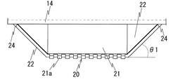
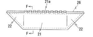
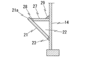
ステップは、中央板部とその左右両側の側板部と上板部とを有し、
前記中央板部は、サイドフレームから離間した上端の足掛部から下端にわたってサイドフレーム側に次第に近接するように傾斜させ、
前記側板部は、前記中央板部の左右両側から前記サイドフレームにわたる範囲に設けられ、両側板部の上端間の間隔がサイドフレームに近接するほど次第に広くなり、側板部の外面が斜め下向きとなるように傾斜させ、
前記上板部は前記中央板部と前記両側板部のうち少なくとも両側板部に溶接し、
前記上板部を前記サイドフレームにも溶接すると共に、前記側板部の側部および前記中央板部の下部も前記サイドフレームに溶接したことを特徴とする。
Claims (1)
- 建設機械の下部走行体を構成するサイドフレームに取付けられる昇降用ステップ装置において、
ステップは、中央板部とその左右両側の側板部と上板部とを有し、
前記中央板部は、サイドフレームから離間した上端の足掛部から下端にわたってサイドフレーム側に次第に近接するように傾斜させ、
前記側板部は、前記中央板部の左右両側から前記サイドフレームにわたる範囲に設けられ、両側板部の上端間の間隔がサイドフレームに近接するほど次第に広くなり、側板部の外面が斜め下向きとなるように傾斜させ、
前記上板部は前記中央板部と前記両側板部のうち少なくとも両側板部に溶接し、
前記上板部を前記サイドフレームにも溶接すると共に、前記側板部の側部および前記中央板部の下部も前記サイドフレームに溶接したことを特徴とする建設機械の昇降用ステップ装置。
Priority Applications (1)
| Application Number | Priority Date | Filing Date | Title |
|---|---|---|---|
| JP2009066891A JP5116713B2 (ja) | 2009-03-18 | 2009-03-18 | 建設機械の昇降用ステップ装置 |
Applications Claiming Priority (1)
| Application Number | Priority Date | Filing Date | Title |
|---|---|---|---|
| JP2009066891A JP5116713B2 (ja) | 2009-03-18 | 2009-03-18 | 建設機械の昇降用ステップ装置 |
Publications (2)
| Publication Number | Publication Date |
|---|---|
| JP2010216191A JP2010216191A (ja) | 2010-09-30 |
| JP5116713B2 true JP5116713B2 (ja) | 2013-01-09 |
Family
ID=42975300
Family Applications (1)
| Application Number | Title | Priority Date | Filing Date |
|---|---|---|---|
| JP2009066891A Active JP5116713B2 (ja) | 2009-03-18 | 2009-03-18 | 建設機械の昇降用ステップ装置 |
Country Status (1)
| Country | Link |
|---|---|
| JP (1) | JP5116713B2 (ja) |
Families Citing this family (1)
| Publication number | Priority date | Publication date | Assignee | Title |
|---|---|---|---|---|
| JP6697371B2 (ja) * | 2016-11-18 | 2020-05-20 | 日立建機株式会社 | 建設機械 |
Family Cites Families (3)
| Publication number | Priority date | Publication date | Assignee | Title |
|---|---|---|---|---|
| JP3685379B2 (ja) * | 2000-03-01 | 2005-08-17 | 日立建機株式会社 | 建設機械の昇降ステップ装置 |
| JP2004142669A (ja) * | 2002-10-25 | 2004-05-20 | Sumitomo (Shi) Construction Machinery Manufacturing Co Ltd | 建設機械のステップ装置 |
| JP2006088723A (ja) * | 2004-09-21 | 2006-04-06 | Hitachi Constr Mach Co Ltd | 建設機械における昇降用ステップ装置 |
-
2009
- 2009-03-18 JP JP2009066891A patent/JP5116713B2/ja active Active
Also Published As
| Publication number | Publication date |
|---|---|
| JP2010216191A (ja) | 2010-09-30 |
Similar Documents
| Publication | Publication Date | Title |
|---|---|---|
| CN103362159B (zh) | 用于工业机械的吊杆和铲斗柄部组件 | |
| JP6413012B2 (ja) | 作業車両の昇降ステップ | |
| CN1904235B (zh) | 支承建筑机械驾驶室的上框架的结构 | |
| US9688204B2 (en) | Ladder of working vehicle | |
| CN105164342B (zh) | 旋转机架和包括该机架的作业机械 | |
| JP4741298B2 (ja) | 建設機械のカウンタウエイト装置 | |
| JP5116713B2 (ja) | 建設機械の昇降用ステップ装置 | |
| JP4609570B2 (ja) | 建設機械のフレーム構造 | |
| JP2007205100A (ja) | 建設機械の車体フレームおよび建設機械 | |
| CN105408551B (zh) | 作业车辆用铲斗及具有该铲斗的作业车辆 | |
| JP2008291541A (ja) | 建設機械 | |
| JP5274542B2 (ja) | 建設機械のトラックフレーム | |
| JP5430606B2 (ja) | 双腕型作業機 | |
| JP2010065436A (ja) | ローダ作業機のキャビン装置 | |
| JP5119099B2 (ja) | ローダ作業機 | |
| JP6331836B2 (ja) | 建設機械 | |
| JP5430607B2 (ja) | 双腕型作業機 | |
| JP5533936B2 (ja) | 建設機械 | |
| JP5753511B2 (ja) | 解体機用キャブ及びこれに用いるキャブガード | |
| JP2010065482A5 (ja) | ||
| JP2010059683A5 (ja) | ||
| JP2010059683A (ja) | ローダ作業機 | |
| WO2025150500A1 (ja) | 走行装置吊り具および走行装置吊り上げ方法 | |
| JP6735256B2 (ja) | 建設機械用作業機の載置台装置 | |
| JP5112149B2 (ja) | 柱支持構造および建設機械用キャブ |
Legal Events
| Date | Code | Title | Description |
|---|---|---|---|
| A621 | Written request for application examination |
Free format text: JAPANESE INTERMEDIATE CODE: A621 Effective date: 20110217 |
|
| A977 | Report on retrieval |
Free format text: JAPANESE INTERMEDIATE CODE: A971007 Effective date: 20120531 |
|
| A131 | Notification of reasons for refusal |
Free format text: JAPANESE INTERMEDIATE CODE: A131 Effective date: 20120801 |
|
| A521 | Written amendment |
Free format text: JAPANESE INTERMEDIATE CODE: A523 Effective date: 20120828 |
|
| TRDD | Decision of grant or rejection written | ||
| A01 | Written decision to grant a patent or to grant a registration (utility model) |
Free format text: JAPANESE INTERMEDIATE CODE: A01 Effective date: 20121016 |
|
| A01 | Written decision to grant a patent or to grant a registration (utility model) |
Free format text: JAPANESE INTERMEDIATE CODE: A01 |
|
| A61 | First payment of annual fees (during grant procedure) |
Free format text: JAPANESE INTERMEDIATE CODE: A61 Effective date: 20121016 |
|
| R150 | Certificate of patent or registration of utility model |
Ref document number: 5116713 Country of ref document: JP Free format text: JAPANESE INTERMEDIATE CODE: R150 Free format text: JAPANESE INTERMEDIATE CODE: R150 |
|
| FPAY | Renewal fee payment (event date is renewal date of database) |
Free format text: PAYMENT UNTIL: 20151026 Year of fee payment: 3 |